

NATIONAL CONTROLS Q8F-00005-321, Q8F User Manual
1-30
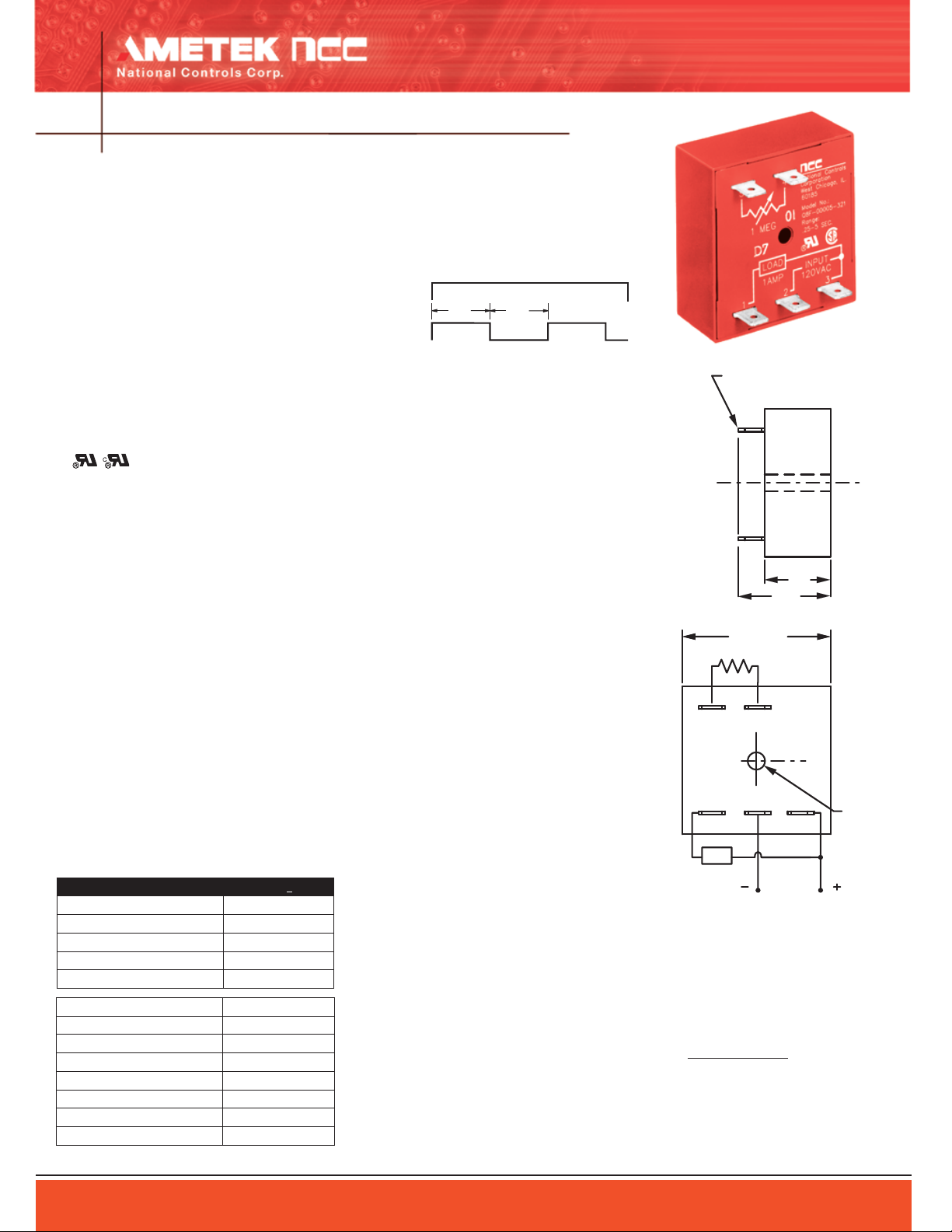
On
Of
f
On
Of
f
Input
V
oltage
Load
Timing
Timing
45
1.25
.88
321
L
C
L
C
Rt
.25 X .032 MALE FAST-ON
TERMINALS (5 PL.)
2.00 SQ.
.170
DIA.
(3667-7)
LOAD
VOLTAGE
INPUT
Polarity Shown is
for DC Models
TIME DELAY RELAYS
Flasher
Q8F Series
FEATURES
100% functionally tested
●
Only one timing component required
●
Solid state digital timing
●
Time delays to 5 minutes standard
●
20:1 maximum to minimum timing ratio
●
●
Low cost
●
Compact size
●
Superior transient protection
●
Flame-retardant and solvent-resistant
polyester thermoplastic housing
●
Operating Logic: Upon application of volt
age to the input terminals, the load is ener
gized for the duration of the preset time
delay. At the end of this time delay, the load
is de-energized for the duration of the pre
set time delay. The load is then energized
again and the timer continues to repeat this
on-off cycle until input voltage is removed.
Both on and off times are the same and are
determined by Rt.
Note: 1) Rt and terminals 4 and 5 are used for external time
adjustment; 2) Remote potentiometer leads should be shielded
when running close to other wires; 3) The minimum time setting
on external resistor-adjustable time delay relays is obtained by
shorting together the external resistor terminals of the relay; 4)
The maximum time setting within tolerance limits is obtained by
using a 1 megohm resistor; 5) Timing values between the minimum and maximum limits are linear with resistance within 10%;
6) Recommend 1/4 W minimum resistor be used.
File #E65038
LOGIC FUNCTION DIAGRAM
SPECIFICATIONS
TIME DELAY
Adjustment: External resistor, factory fixed on
special order (min. order requirement)
Range: 50 ms to 5 minutes in 5 ranges
Repeatability: ±.5% +8 ms max. (0.25% typical)
-
at constant temperature
-
Accuracy:
Maximum time ±2% at Rt = 1 megohm
Minimum time +0%, -30% at Rt = 0 ohm
-
INPUT
Operating Voltage: 120 VAC ±10%
Frequency: 50/60 Hz
OUTPUT
Type: Solid state, normally open
Rating: 1 A steady state
Life: 100,000,000 operations
PROTECTION
Transient Voltage: Metal oxide varistor (see rat-
ing below)
Dielectric Breakdown: 3000 VAC, RMS, termi
nals to mounting
Insulation Resistance: 100 megohms min.
-
between terminals and case
MECHANICAL
Termination: .25” x .032” male fast-on terminals
Mounting: Surface mount with one #8 screw
ENVIRONMENTAL
ORDERING INFORMATION
Trigger time (start switch closure)
Reset time 500 ms
Min. load 2 mA
Max. leakage current 100 uA
Voltage drop at 1 A 3.3 V
Power consumption 4.3 VA max.
Peak 1 cycle surge 20 A
Protection 30j. MOV
Optional Potentiometer: Part Number ASY-0001M-450
AMETEK National Controls Corp. • 1725 Western Drive • West Chicago, Illinois 60185 • Tel: 800-323-2593 • 630-231-5900 • FAX: 630-231-1377 • www.nationalcontrols.com
TIME RANGE 120 VAC +10%
.05 to 1 sec. Q8F-00001-321
.25 to 5 sec.
.5 to 10 sec.
3 to 60 sec.
15 to 300 sec.
Q8F-00005-321
Q8F-00010-321
Q8F-00060-321
Q8F-00300-321
500 ms
Storage Temperature: -40°C to 85°C
Operating Temperature: -40°C to 65°C
Humidity: 95% relative
External Resistance/Time Delay Relationship
1 megohm external resistance is required to obtain
the maximum time for all ranges. To determine the
actual resistance needed to obtain the required time
delay, use the following formula:
Trequired - Tminimum
Rt=
Tmaximum - Tminimum
Note: Due to component tolerances, the actual time
obtained will normally be within 5% of desired time.
Consult factory for any special requirements not
listed in catalog (minimum order requirement may
apply).
x 1,000,000 ohms
 Loading...