

NATIONAL CONTROLS Q4F-00001-327 User Manual
Phone 800-323-2593
N a ti o n a l C o n t r ol s C o r p.
C
R
R
Timing
On
Off
On
Off
Input
Voltage
Load
Logic Function Diagram:
.88
1.25
Rt
5 4
2.00 SQ.
L
C
C
L
321
(3667-7)
.25 X .032 MALE FAST-ON
TERMINALS (7 PL.)
.170
DIA.
LOAD
INPUT
VOLTAGE
Polarity Shown is
for D.C. Models
630-231-5900
Fax 630-231-1377
Internet www.natcon.com
www.nationalcontrols.com
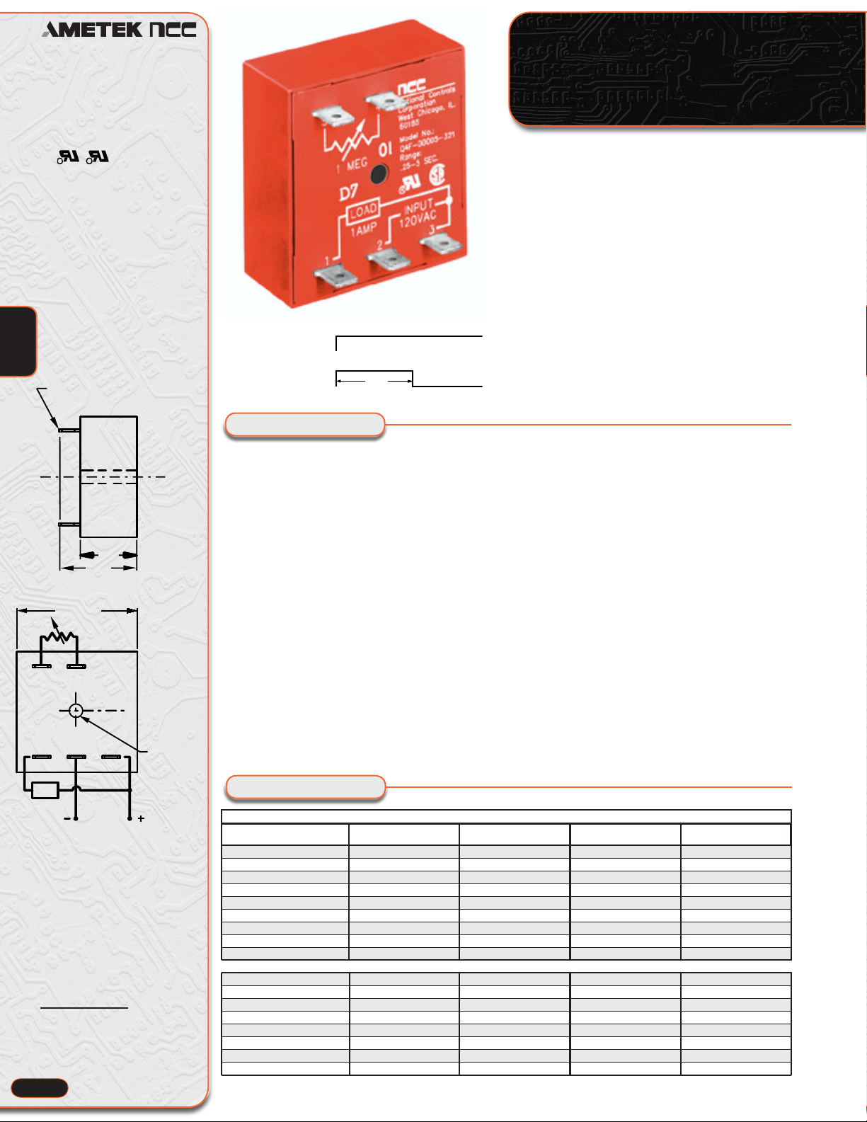
Solid-State
Cube Timers
Features
Time Delays To 10 Hours
Standard
100% Life Tested
Solid-State Digital Timing
20:1 Maximum To
Minimum Timing Ratio
Low Cost
Compact Size
Superior Transient
Protection
Flame-Retardant and
Solvent-Resistant
1
Polyester Thermoplastic
Housing
Made in U.S.A.
File #E65038
Specifications
Time Delay
Adjustment: External resistor, factory fixed on
special order (Minimum order requirement)
Range: 50 mS to 10 hours in 9 ranges
Repeatability: ±.5% + 8 mS maximum (0.25%
typ.) at constant temperature.
Accuracy:
Maximum time ± 2% at Rt = 1 megohm
Minimum time +0%-30% at Rt = 0 ohm
Input
Operating Voltage: 120, 24 VAC/DC ± 10%
(D.C. models have reverse polarity protection.
Unfiltered input voltage to them must be fullwave rectified)
Frequency: 50/60 Hz
Output
Type: Solid-state, normally open
Rating: 1 amp. steady state
Life: 100,000,000 operations
Interval
Q4F Series
Operating Logic: Upon application of input
voltage the load energizes and the timing cycle
starts. At the completion of the preset time delay,
the load is de-energized. Reset is accomplished by
removal of input voltage.
Note:1) Remote potentiometer leads should be shielded when running
close to other wires; 2) The minimum time setting on external resistoradjustable time delay relays is obtained by shorting together the external
resistor terminals of the relay; 3) The maximum time setting within
tolerance limits is obtained by using a 1 megohm resistor ; 4) Timing
values between the minimum and maximum limits are linear with
resistance within 10%; 5) Recommend 1/4 watt minimum resistor be
used.
Protection
Transient Voltage: Metal oxide varistor, see rat-
ings below
Dielectric Breakdown: 3000 VAC, RMS, termi-
nals to mounting
Insulation Resistance: 100 megohms minimum
between terminals and case
Mechanical
Termination: .25" x .032" male fast-on terminals
Mounting: Surface mount with one #8 screw
Environmental
Storage Temperature: -40°C to 85°C
Operating Temperature: -40°C to 65°C
Humidity: 95% relative
External Resistance/Time
Delay Relationship
1 megohm external resistance is
required to obtain the maximum
time for all ranges. To determine
the actual resistance needed to
obtain the required time delay, use
the following formula:
Rt =
Note: Due to component tolerances, the
actual time obtained will normally be
within 5% of desired time.
Trequired - Tminimum
Tmaximum - Tminimum
1-28
x 1,000,000 ohms
Ordering Information
Input Voltage and Appropriate Part Numbers
Time Range
.05-1 Second Q4F-00001-326 Q4F-00001-327
.25-5 Seconds
.5-10 Seconds
3-60 Seconds Q4F-00060-326 Q4F-00060-327
15-300 Seconds Q4F-00300-326 Q4F-00300-327
30-600 Seconds Q4F-00600-326 Q4F-00600-327
180-3600 Seconds Q4F-03600-326 Q4F-03600-327
.25-5 Hours Q4F-18000-326 Q4F-18000-327
.5-10 Hours Q4F-36000-326 Q4F-36000-327
Trigger Time (Start Sw. Closure)
Reset Time 75 mS 50 mS 150 mS 150 mS
Min. Load 5 mA 5 mA 2 mA 2 mA
Max. Leakage Current 20 uA 20 uA 100 uA 100 uA
Voltage Drop @ 1A 2.1 Volts 3.2 Volts 3.3 Volts 3.3 Volts
Power Consumption 3.0 Watts Max. 3.0 VA Max. 3.0 VA Max. 3.0 VA Max.
Peak 1 Cycle Surge 4 Amp 4 Amp 20 Amp 20 Amp
Protection rev. volt / 8.8j. MOV 8.8j. MOV 30j. MOV 30j. MOV
Optional Potentiometer: Part Number ASY-0001M-450
12 VDC ± 10% 24 VAC/DC ± 10%
Q4F-00005-326 Q4F-00005-327
Q4F-00010-326 Q4F-00010-327
75 mS 50 mS 150 mS 150 mS
120 VAC ± 10% 240 VAC ± 10%
Q4F-00001-321 Q4F-00001-325
Q4F-00005-321 Q4F-00005-325
Q4F-00010-321 Q4F-00010-325
Q4F-00060-321 Q4F-00060-325
Q4F-00300-321 Q4F-00300-325
Q4F-00600-321 Q4F-00600-325
Q4F-03600-321 Q4F-03600-325
Q4F-18000-321 Q4F-18000-325
Q4F-36000-321 Q4F-36000-325
 Loading...