

NATIONAL CONTROLS Q2F-00001-326, Q2F User Manual
1-16
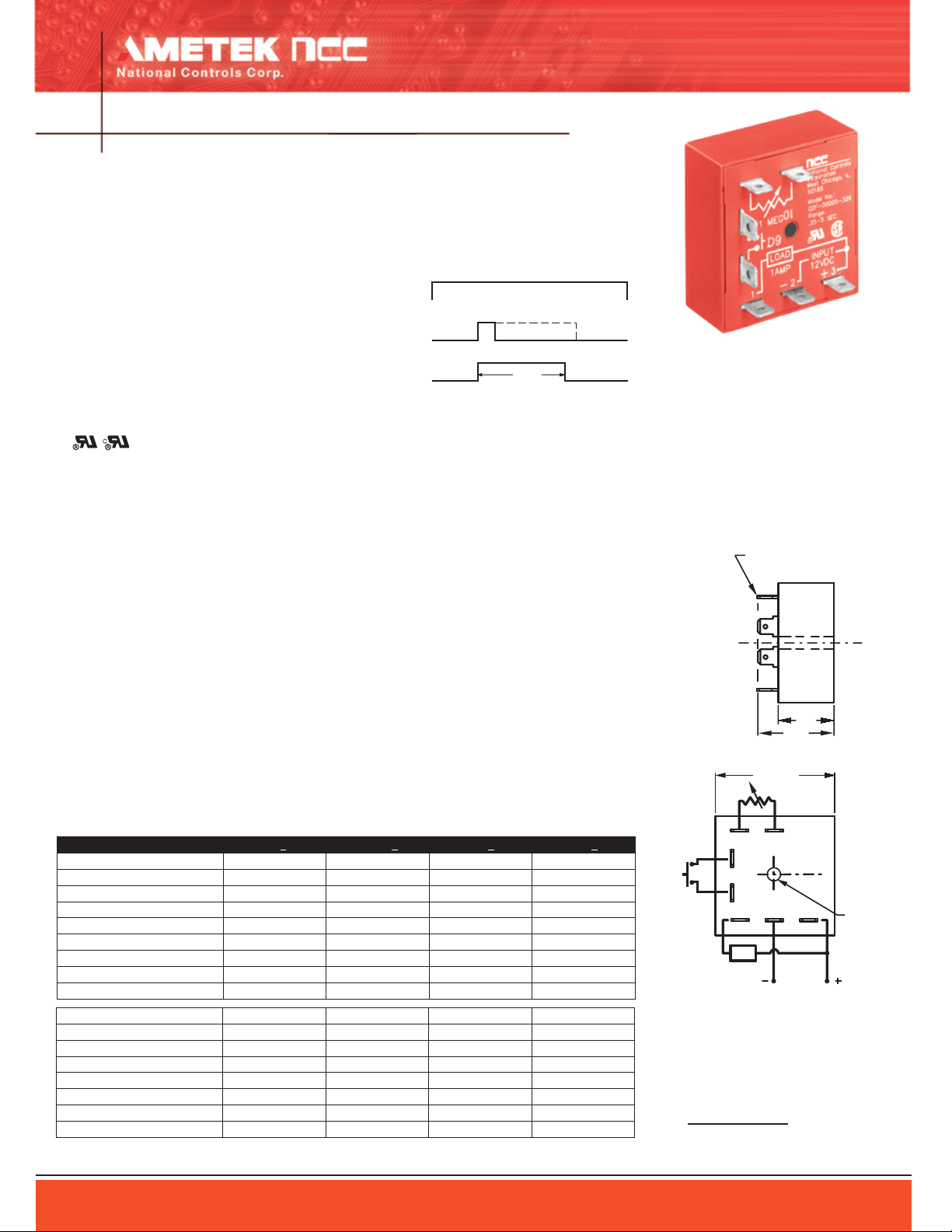
Timing
On
Off
On
Off
Input
Voltage
Load
OpenSwitch
Start Closed
Single Shot Function
76
.88
1.25
Rt
5 4
2.00 SQ.
L
C
C
L
321
START
(3667-4)
.25 X .032 MALE FAST-ON
TERMINALS (7 PL.)
.170
DIA.
SWITCH
LOAD
INPUT
VOLTAGE
Polarity Shown is
for D.C. Models
TIME DELAY RELAYS
Single Shot
Q2F Series
FEATURES
100% functionally tested
●
Solid state digital timing
●
Time delays to 10 hours standard
●
20:1 maximum to minimum timing ratio
●
Low cost
●
●
Compact size
●
Superior transient protection
●
Flame-retardant and solvent-resistant
polyester thermoplastic housing
●
File #E65038
Operating Logic: Input voltage is applied to
the timer at all times. Upon a momentary or
maintained closure of a normally open iso
lated start switch, the load energizes and
the time delay starts. At the end of the pre
set time delay, the load de-energizes and
the timer is ready for a new timing cycle.
(Start switch supplied by customer)
Note: 1) Remote start switch leads should be shielded when running close to other wires; 2) Remote potentiometer leads should
be shielded when running close to other wires; 3) The minimum
time setting on external resistor-adjustable time delay relays is
obtained by shorting together the external resistor terminals of
the relay; 4) The maximum time setting within tolerance limits is
obtained by using a 1 megohm resistor; 5) Timing values between
the minimum and maximum limits are linear with resistance within
10%; 6) Recommend 1/4 W minimum resistor be used.
ORDERING INFORMATION
LOGIC FUNCTION DIAGRAM
SPECIFICATIONS
TIME DELAY
Adjustment: External resistor factory fixed on
special order (min. order requirement)
Range: 50 ms to 10 hours in 9 ranges
Repeatability: ±.5% +8 ms max. (0.25% typical)
at constant temperature
Accuracy:
Maximum time ±2% at Rt = 1 megohms
Minimum time +0%, -30% at Rt = 0 ohm
INPUT
Operating Voltage: 120, 240 VAC; 12 VDC; 24
VAC/DC ±10% (DC models have reverse polarity
protection; unfiltered input voltage to them must
be full-wave rectified)
Frequency: 50/60 Hz
OUTPUT
Type: Solid state, normally open
Rating: 1 A steady state
Life: 100,000,000 operations
PROTECTION
Transient Voltage: Metal oxide varistor, see rat-
ings below
Dielectric Breakdown: 3000 VAC, RMS, termi
nals to mounting
-
Insulation Resistance: 100 megohms
min. between terminals and case
MECHANICAL
Termination: .25” x .032” male fast-on
terminals
Mounting: Surface mount with one #8
screw
ENVIRONMENTAL
Storage Temperature: -40°C to 85°C
Operating Temperature: -40°C to 65°C
Humidity: 95% relative
TIME RANGE 12 VDC +10% 24 VAC/DC +10% 120 VAC +10% 240 VAC +10%
.05 to 1 sec. Q2F-00001-326 Q2F-00001-327 Q2F-00001-321 Q2F-00001-325
.25 to 5 sec.
.5 to 10 sec.
3 to 60 sec.
15 to 300 sec.
30 to 600 sec.
180 to 3600 sec.
.25 to 5 hrs.
Trigger time (start switch closure)
Reset time 200 ms 300 ms 300 ms 200 ms
Min. load 5 mA 5 mA 2 mA 2 mA
Max. leakage current 10 uA 10 uA 200 uA 300 uA
Voltage drop at 1 A 2.1 V 3.2 V 3.3 V 3.3 V
Power consumption 2.6 W 3.7 VA max. 4.3 VA max. 5.8 VA max.
Peak 1 cycle surge 4 A 4 A 20 A 20 A
Protection 8.8j. MOV 8.8j. MOV 30j. MOV 30j. MOV
Optional Potentiometer: Part Number ASY-0001M-450
Consult factory for any special requirements not listed in catalog (minimum order requirement may apply).
AMETEK National Controls Corp. • 1725 Western Drive • West Chicago, Illinois 60185 • Tel: 800-323-2593 • 630-231-5900 • FAX: 630-231-1377 • www.nationalcontrols.com
.5 to 10 hrs.
Q2F-00005-326 Q2F-00005-327 Q2F-00005-321 Q2F-00005-325
Q2F-00010-326 Q2F-00010-327 Q2F-00010-321 Q2F-00010-325
Q2F-00060-326 Q2F-00060-327 Q2F-00060-321 Q2F-00060-325
Q2F-00300-326 Q2F-00300-327 Q2F-00300-321 —
Q2F-00600-326 Q2F-00600-327 Q2F-00600-321 Q2F-00600-325
Q2F-03600-326 Q2F-03600-327 Q2F-03600-321 —
Q2F-18000-326 Q2F-18000-327 Q2F-18000-321 Q2F-18000-325
Q2F-36000-326 — Q2F-36000-321 —
20 ms 20 ms 20 ms 20 ms
External Resistance/Time Delay Relationship
1 megohm external resistance is required to obtain
the maximum time for all ranges. To determine the
actual resistance needed to obtain the required time
delay, use the following formula:
Trequired - Tminimum
Rt=
Tmaximum - Tminimum
Note: Due to component tolerances, the actual time
obtained will normally be within 5% of desired time.
x 1,000,000 ohms
 Loading...