

NATIONAL CONTROLS IST-200T User Manual
5-6
UNDER
OVER
L1
L2
COM
NO
NC
min.
max.
max.
min.
POINT
TRIP
FAULT
CURRENT
CURRENT
MODE SELECT SWITCH
NON-
LATCH
LATCH
AC CURRENT SENSOR
TRIP
DELAY
MOTOR
ALARM
Motor
Supply
Voltage
120 or 240 VAC
Input Voltage
SETTINGS:
TRIP POINT: approx. 10 amps
TRIP DELAY: approx. 4.5 sec.
MODE SELECT SWITCH:
Non-Latching
Over-Current
CURRENT MONITORS
2-20 A Current Monitor
IST-200T Series
FEATURES
100% functionally tested
●
Low cost
●
Fault status LED
●
Adjustable trip delay timer
●
Adjustable trip point from 2 to 20 A
●
●
Selectable ouput modes:
– Latching
– Non-latching
Selectable sensing modes:
●
– Over-current
– Under-current
120 VAC and 240 VAC models
●
50/60 Hz operation
●
SPDT 10 A relay output
●
●
Epoxy encapsulated
●
File #E59090
through the torroid transformer; two
turns would change the range to 1 to
10 A, four turns would change it to 0.5 to
5 A.
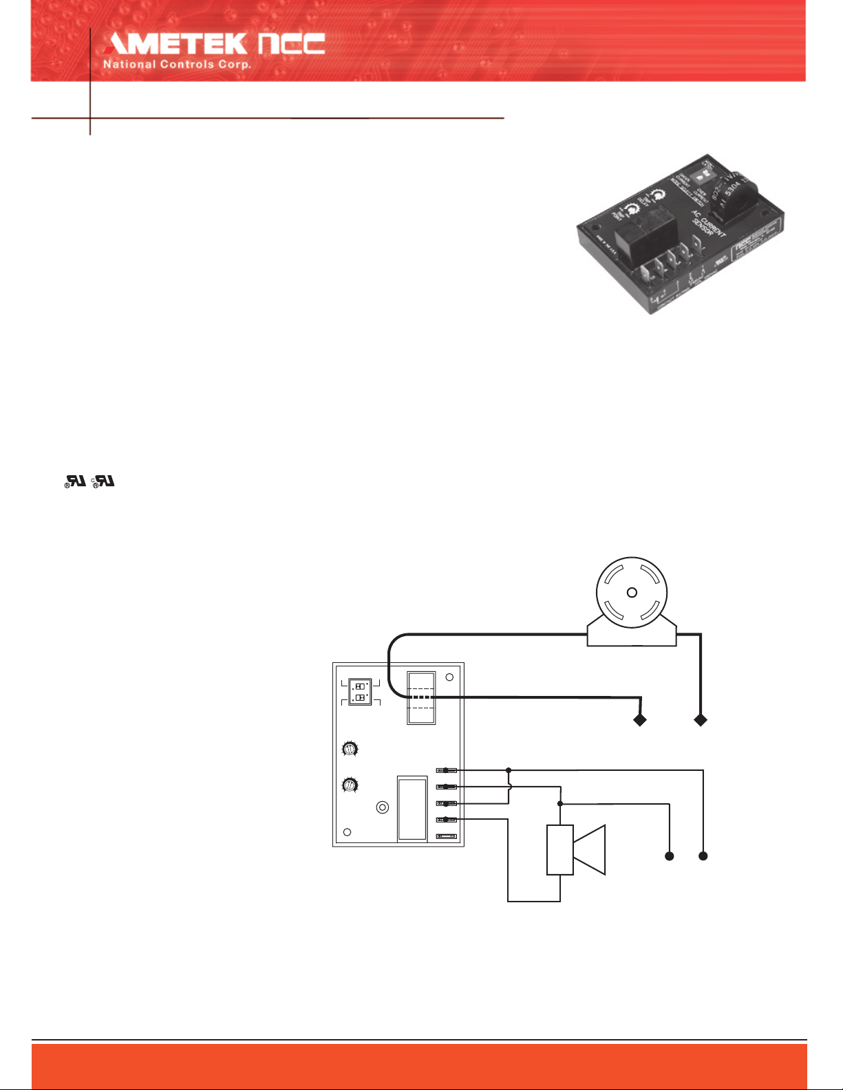
TYPICAL APPLICATION
As long as the operating current of the
motor is less than 10 A, the alarm will not
sound. If the motor draws greater than 10 A
for longer than 4.5 seconds, the FAULT LED
will light and the alarm will sound. Because
the NON-LATCH mode is set, the fault con
dition will clear as soon as the current draw
of the motor drops below 10 A. When the
fault is cleared, the FAULT LED will turn off
and the alarm will stop sounding. If, how
ever, the LATCH mode was selected and
an OVER-CURRENT fault is detected, the
fault will not clear when the motor current
-
draw dropped below 10 A. In this case, the
Operating Logic: The Current Monitor
senses AC load current passing through its
torroid transformer. In the OVER-CURRENT
mode, the on-board relay will initiate the
alarm would continue to sound until reset of
the Current Sensor by either removing and
reapplying power or by switching to NONLATCH mode.
TRIP DELAY timer and illuminate the FAULT
LED when the sensed current is greater
than the TRIP POINT setting. If the sensed
current is still greater than the TRIP POINT
setting after the TRIP DELAY timer has
elapsed, the on-board relay will energize.
If the UNDER-CURRENT mode is select
ed, the on-board relay will be un-energized
as long as the sensed current is greater
than the TRIP POINT setting. Once the
sensed current drops below the TRIP POINT
setting, the TRIP DELAY timer will start tim
ing and the FAULT LED will illuminate. If the
sensed current is still less than the TRIP
POINT setting after the TRIP DELAY time
has elapsed, the on-board relay will ener
gize and its contacts will change state.
The Current Monitor will automatically
-
reset itself when the sensed current returns
to its non-fault value if the NON-LATCH
mode is selected. However, if the LATCH
mode is selected, the on-board relay will
remain energized regardless of any sub
sequent change in the sensed current. To
reset the fault in this mode, either remove
input power from unit and reapply it, or
switch to NON-LATCH mode.
The Current Monitor is designed to sense
a range of 2 to 20 A with a single loop of the
load wire passed through the torroid trans
-
former. Greater sensitivity can be achieved
by passing multiple loops of the load wire
AMETEK National Controls Corp. • 1725 Western Drive • West Chicago, Illinois 60185 • Tel: 800-323-2593 • 630-231-5900 • FAX: 630-231-1377 • www.nationalcontrols.com
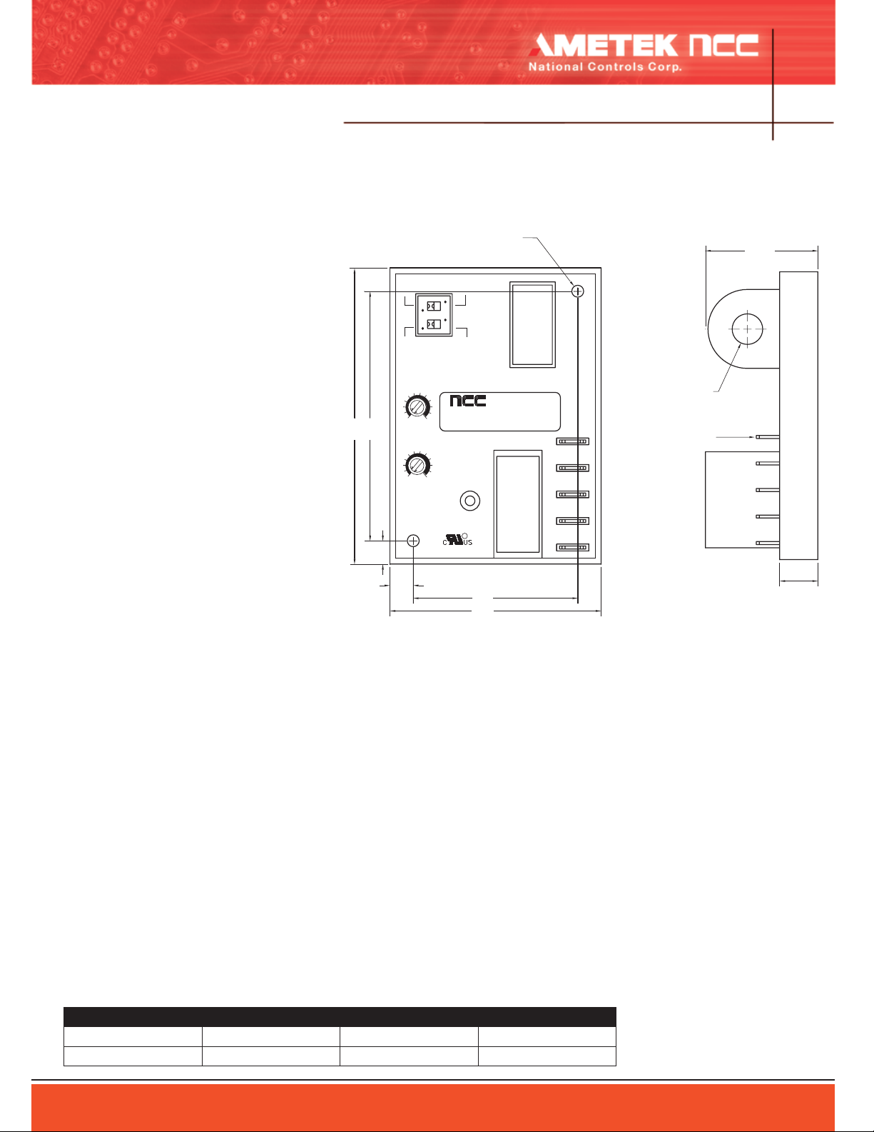
SPECIFICATIONS
TERMINALS ARE
QUICK CONNECT (5
)
.25 X .032
MOUTING HOLES (2)
.188 DIA.
.375 DIA.
.50 [12.7]
1.94
.28
2.94
.28
1.375
MAX.
3.50
2.50
R
Corporation
National Controls
West Chicago, IL. 60185
UNDER
OVER
L1
L2
COM
NO
NC
min.
MADE IN THE U.S.A .
max.
max.
min.
POINT
TRIP
FAULT
CURRENT
CURRENT
MODE SELECT SWITCH
NON-
LATCH
LATCH
AC CURRENT SENSOR
CONTACT RATING: 10A, 250VAC
TRIP
DELAY
Model: IST-200T*-14* INPUT:***VAC
Range: 2-20 AMPS, .*-** seconds
INPUT
Operating Voltage:
IST-200TA-141: 105 to 135 VAC, 50/60 Hz
IST-200TA-145: 210 to 270 VAC, 50/60 Hz
Power Consumption: 3.5 VA max.
Current Sense Input: 0 to 40 A steady-state
200 A inrush for 100 ms max.
OUTPUT
Type: Relay contacts SPST (1 form C)
Rating: 10 A resistive, 1/2 hp at 250 VAC
Life:
Mechanical: 1,000,000 operations
Electrical: 100,000 operations at full load
CURRENT SENSE ADJUSTMENT
Range: 2 to 20 A with single load wire through
sensor, Trimpot adjustable
Power-up surge delay: 100 ms max.
Response time: 100 ms max. over or under cur
rent mode
CURRENT TRIP DELAY ADJUSTMENT
Range: 0.1 to 10 sec., Trimpot adjustable
MECHANICAL
Termination: 5 - .25” x .032” male fast-on
terminals
Mounting: 3.5” x 2.5” encapsulated enclosure
with 2 mounting holes suitable for #8 screw
ENVIRONMENTAL
Storage Temperature: -40°C to +85°C
Operating Temperature: -40°C to +65°C
CURRENT MONITORS
5-7
-
ORDERING INFORMATION
AMETEK National Controls Corp. • 1725 Western Drive • West Chicago, Illinois 60185 • Tel: 800-323-2593 • 630-231-5900 • FAX: 630-231-1377 • www.nationalcontrols.com
INPUT VOLTAGE TRIP POINT TRIP DELAY PART NUMBER
120 VAC 2 to 20 A .1 to 10 sec. IST-200TA-141
240 VAC 2 to 20 A .1 to 10 sec. IST-200TA-145
 Loading...