

NATIONAL CONTROLS DNC-T2610-010 Installation Manual
DNC-T2610-010 / DNC-T2610-020
PULSE JET
DUST COLLECTOR CONTROLLER
NationalControlsCorp.
• Phone 800-323-2593
• Fax 630-231-1377
• www.nationalcontrols.com MII-T2610-011
Operation and Installation
Manual
National Controls C orp.

N ationalControls C orp. N ationalControls C orp.
Phone 800-323-2593 • Fax 630-231-1377 • www. nationalcontrols.com
Phone 800-323-2593 • Fax 630-231-1377 • www.natio nalcontrols.com
Dustronix T2610 Operation Manual
Table of Contents
Warranty 3
Important Notice to Users 3
1.0 System Overview 3
2.0 Installing the Controls 4
3.0 Electrical Hookup 5
4.0 DNC-T2610-010 Control Module Operation 6
4.1. RUN Mode 6
4.2. Cycle Down Mode 7
4.3. Standby Mode 7
4.4. Program Mode 7
5.0 Programming the Control Module 8
5.1. Solenoid Output 8
5.2. Solenoid On Time 9
5.3. Solenoid Off Time 9
5.4. Number of Cycle Down Cycles 9
5.5. Cycle Down Delay Time 9
5.6. Standby 9
5.7. ∆ Pressure High Set Point 10
5.8. ∆ Pressure Low Set Point 10
5.9. ∆ Pressure High Alarm Set Point 10
5.10. ∆ Pressure Low Alarm Set Point 10
5.11. Alarm 11
5.12. ∆ Pressure 11
5.13. Output 11
6.0 Control Module Status LEDs 11
6.1. Alarm (Display Status) 11
6.2. ∆ Pressure 11
6.3. Output 11
6.4. Alarm (System Status) 14
6.5. Output Pulsing 14
6.6. Cycle Down 14
6.7. Output Status 14
6.8. CANbus Status 14
7.0 Control Module Default Values 14
8.0 Control Module Specifications 15
9.0 DNC-T2610-020 Expansion Module Overview 17
10.0 Expansion Module Operation 17
11.0 Expansion Module Programming 17
12.0 Expansion Module Addressing 17
13.0 Expansion Module LEDs 18
13.1. Output Status 18
13.2. CANbus 18
13.3. Communications Jumper Logic 18
14.0 Expansion Module
15.0 Expansion Module
Default Values
Specifications 19
18
WARRANTY:
All of National Controls' products are warranted for a period of 1
year against defects and workmanship. Because certain conditions
may apply to different product categories, contact the factory for
detailed warranty information.
IMPORTANT NOTICE TO USERS:
NCC products are capable of use in a wide array of devices and
applications. Any device or system incorporating a NCC product
should be designed that, in the event of failure, malfunction, or
normal wear of the product, the device or system will become
inoperative in a manner which will prevent bodily injury or
property damage. In order to keep abreast with the latest
technology, National Controls Corporation reserves the right to
change components, design, and specifications without notice.
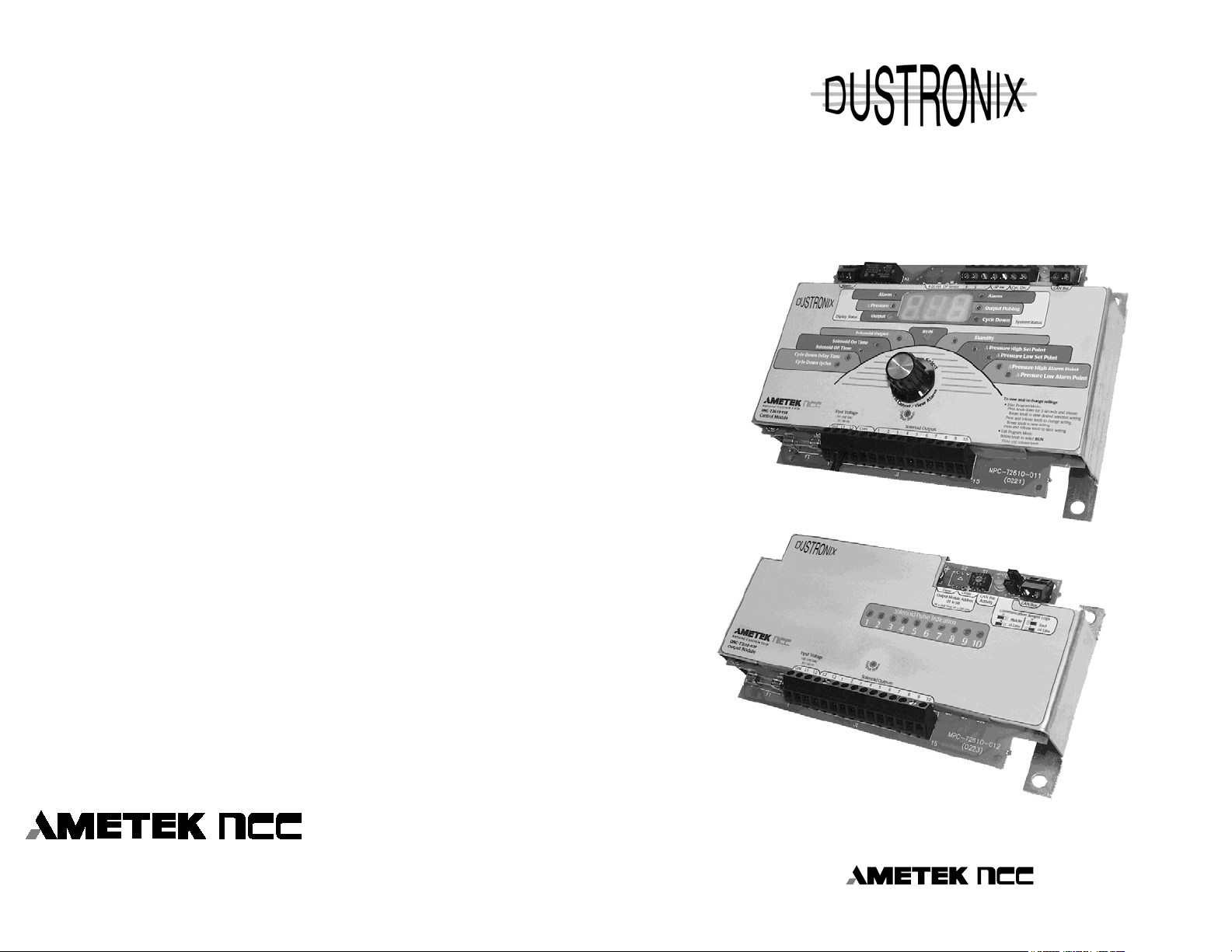
1.0 SYSTEM OVERVIEW
The Dustronix DNC-T2610-010 and DNC-T2610-020 Dust
Collector Control System’s flexible design allows it to be adapted
to many dust collector configurations. The DNC-T2610-010
Control Module will sequentially pulse up to ten outputs in “OnDemand” mode either based upon a Pressure Switch closure or a 4
– 20mA current loop signal originating from an external
Differential Pressure (∆P) Sensor. If more output capability is
needed, up to 980 additional outputs can be controlled with
multiple DNC-T2610-020 Expansion Modules connected to the
Controller. Furthermore, the controller features a current sensing
capability, which allows electrical fault monitoring for up to three
solenoids per output. This capability makes it possible to control
and monitor up to 2,970 individual solenoids from one Control
Module, and has the added convenience of providing an Auto
Configuration option for ease in initial setup.
Additionally, the simple five step intuitive programming
procedure makes it easy to setup or change any program item.
Using a single Pushbutton/Encoder along with 19 LED’s and a 3digit display, the programming procedure can be self-taught in
Dustronix T2610 Operation Manual Page 2 Dustronix T2610 Operation Manual Page 3

N ationalControls C orp. N ationalControls C orp.
Phone 800-323-2593 • Fax 630-231-1377 • www. nationalcontrols.com
Phone 800-323-2593 • Fax 630-231-1377 • www.natio nalcontrols.com
less than one minute. Following is a list of the user programmable
Controller functions:
• Cycle Down Mode
• Solenoid Pulse Times
• Auto or Manual Output Configuration
• Run/Standby Mode
• ∆ Pressure Control Set Points
• ∆ Pressure Alarm Set Points
• Alarm Contact Configuration (N.O. or N.C.)
• ∆ Pressure Sensor Selection
• Output Pulsing Options
A universal input power supply lets you apply nominal input
voltage ranging from 100 to 240 Vac, 50/60 Hz to the Control and
Expansion Modules, and the supplied voltage will be
correspondingly switched to the outputs. A small 8” x 6”x 4”
enclosure is all that is needed to house the Control Module.
The features of the Dustronix Control System are summarized
below:
• Simple One Knob, Five Step Programming Procedure
• 3-Digit LED display, 19 Diagnostic/Program LED Indicators
• Capable of controlling up to 2,970 solenoids with fault detection
• End of Operation Cleaning Cycle (Cycle Down Mode)
• Extended Pulse “On” Time Range, from .05 sec. to 600 sec.
• Extended Pulse “Off” Time Range, from 1 to 999 sec.
• Standby Mode, for system maintenance
• Contact Closure Input for ∆P Switch Operation
• Three External ∆P Sensor Ranges, 0-10”, 0-15”, and 0-25” w.c.
• Sink/Source Capability for 4-20 mA ∆P Sensor
• High and Low ∆P Alarms
• User Configurable Alarm Output Relay, either N.O. or N.C.
• CAN Bus Interface for communication with Expansion Modules
• Universal Input Voltage: 100 – 240 Vac, 50/60 Hz Nominal
2.0 INSTALLING THE CONTROLS
The Control Module is designed to mount directly into an 8”x 6”x
4” NEMA4 or NEMA4X enclosure, and one Expansion Module
with a Control Module will fit into a 10”x 8”x 4” NEMA4 or
NEMA4X enclosure. Although it is not necessary for operation,
an enclosure with a windowed cover is recommended for ease in
visual inspection of dust collector system status. For custom
mounting in larger enclosures, refer to the drawings (figs. 1 & 2)
for appropriate dimensions.
DO NOT:
Install these controllers in harsh environments without suitable
protection. Improper installation will void the warranty.
Install this unit in an area of high vibration.
Install this unit close to strong magnetic fields.
3.0 ELECTRICAL HOOKUP
Refer to the corresponding wiring diagrams, figures 3 & 4.
Connect Control Module and any Expansion Modules to a utility
power source, which ranges from 100 to 240 Vac 50/60 Hz. Do
not connect this unit to a "converter" or "inverter" type power
source. This unit should be installed on its own 15-amp circuit. Do
not connect this unit to a power source that is subjected to large
switched loads, such as, electric motors, compressors, electric
tools, etc.
WARNING: MAKE SURE THAT THE CIRCUIT THAT YOU
ARE WORKING WITH, IS "TURNED OFF", BEFORE YOU
MAKE THESE CONNECTIONS. SERIOUS INJURY MAY
RESULT IF YOU DO NOT TAKE THE PROPER SAFETY
PRECAUTIONS.
For 120-volt input, connect the "hot" or "high side" of the
incoming power source to "L1" on the terminal strip. Connect the
"return" to "L2" on the terminal strip.
For 240-volt input, connect one side of the 240-volt line to L1 and
connect the other side of the 240-volt line to L2.
Connect the solenoid air valves to the terminal strip. These are
labeled "Solenoid Outputs" and they are numbered 1 through 10.
You can connect more than one solenoid on each output, as long
as you do not exceed the 150VA (Watt) rating on each. The
current sense circuit will only sense up to three solenoids per
output.
The return wires "commons" from the solenoids will return to the
"L2" terminals.
Dustronix T2610 Operation Manual Page 4 Dustronix T2610 Operation Manual Page 5

N ationalControls C orp. N ationalControls C orp.
Phone 800-323-2593 • Fax 630-231-1377 • www. nationalcontrols.com
Phone 800-323-2593 • Fax 630-231-1377 • www.natio nalcontrols.com
4.0 DNC-T2610-010 CONTROL MODULE OPERATION
The Dustronix DNC-T2610-010 Control Module is shipped from
the factory with the default program (see details below). A
Pressure Switch or jumper needs to be connected to the "∆P SW"
input, solenoid(s) connected, and power applied, in order to have a
functioning system. From this point, Program Items can be
tailored to the specific application.
There are four basic modes of operation for the Control Module;
Run, Cycle Down, Standby, and Program.
4.1 RUN Mode
This mode is the normal functional operating state of the
controller. Whether a Differential Pressure (∆P) Switch or a ∆P
Sensor determines solenoid pulsing, the status of the dust collector
is available to the user by the information visible on the display as
well as the information LEDs. If the controller is used in
conjunction with an external 4-20mA ∆P Sensor, the Display will
alternate between the next output to pulse and the sensed ∆P while
the solenoids are pulsing. When the solenoids stop pulsing, the ∆P
is displayed continuously. With ∆P Switch usage, the Display will
read the next output to pulse.
Alarm events are generated either by faulty solenoid detection or
by a ∆P fault detection if an external ∆P Sensor is used. When an
alarm event occurs, the Alarm Relay changes state and the
“System Status Alarm” LED turns on. To acknowledge the alarm
and view its corresponding information, press the “Program
Select” knob once to display the alarm condition. At this time, the
“System Status Alarm” LED changes from red to amber, and the
“Display Status Alarm” LED turns on indicating that the Display
is showing alarm information. Press the knob once again to view
the output that was being pulsed when the alarm event occurred; a
final knob press returns the Display back to showing normal
system status. If there are multiple alarm events, this sequence of
three knob presses will step through all of the outstanding alarm
events currently detected by the controller in order of occurrence.
4.2 Cycle Down Mode
The Cycle Down Mode allows the user to clean the dust collector
filters “off-line” when the fan shuts down by connecting an
auxiliary set of contacts from the ventilation fan to the cycle down
input (CYC. DN.) of the Control Module. The Cycle Down Mode
is enabled by programming a number between 1 and 20 in the
“Cycle Down Cycles” Program Item, and by programming the
“Cycle Down Delay Time” Program Item with a value between 60
and 600 seconds.
If the Cycle Down mode is enabled, normal operation of the
controller occurs when the CYC. DN. Input is shorted. Opening
the CYC. DN. Input will begin the Cycle Down Delay Time,
which is indicated by the flashing Cycle Down LED to the right of
the display, during this time, the solenoid outputs are disabled.
At the end of this delay, the unit will cycle through all the selected
outputs as determined by the number of cycles selected with the
“Cycle Down Cycles” Program Item, beginning at output number
1. After all the cycles are finished, the Cycle Down LED will stop
flashing and turn on steady, when the CYC. DN. input is closed
once again, the unit shall resume normal operation and the Cycle
Down LED will turn off.
4.3 Standby Mode
To allow for normal maintenance or diagnostic investigation, the
Standby Mode feature is available. When the Standby Mode is
invoked, all controller functions operate as in normal RUN Mode
with the exception of the Solenoid Outputs, they are disabled.
4.4 Program Mode
Easy access to view and change the Program Items is available
through the Program Mode. While in the Program Mode, normal
operation of the controller is maintained, and any changes to any
of the Program Items do not take effect until they are saved into
the Program Item memory. In other words, normal dust collector
filter cleaning can continue even while the controller is in
Program Mode. If the controller is allowed to remain in Program
Mode for longer than 90 seconds without any interaction on the
Dustronix T2610 Operation Manual Page 6 Dustronix T2610 Operation Manual Page 7
 Loading...