

NATIONAL CONTROLS DNC-T2310- B220, DNC-T2310-A10 Installation Manual
National Controls Corp.National Controls Corp.
Phone 800-323-2593 ● Fax 630-231-1377 ● Internet www.natcon.com
STANDARD OPERATION MANUAL
TABLE OF CONTENTS
DNC-T2310-A10 / B10
DNC-T2310-A220 / B220
DNC-T2320-A10 / B10
DNC-T2320-A220 / B220
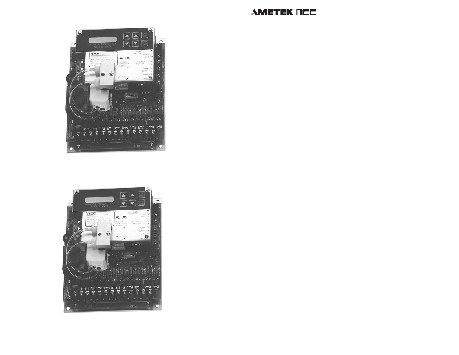
DNC-T2310-A10
DNC-T2320-A10
HOW TO USE THIS GUIDE
OVERVIEW
INSTALLATION INSTRUCTIONS
1.0 MOUNTING THE UNIT
2.0 ELECTRICAL HOOKUP
3.0 ALARM INPUT CONNECTIONS
4.0 ALARM OUTPUT CONNECTIONS
5.0 BYPASS / CYCLE DOWN INPUT CONNECTION
6.0 PRESSURE CONNECTIONS
7.0 4 TO 20 MILLIAMP LOOP
8.0 BEFORE APPLYING POWER TO THE UNIT
9.0 TROUBLESHOOTING
10.0 PLACING THE UNIT INTO “SETUP” MODE
11.0 FACTORY DEFAULT SETTINGS
12.0 USING THE “▲” AND “▼” BUTTONS
13.0 DISPLAY MESSAGES
14.0 PROGRAMMING CONTROLLER PARAMETERS
IDC PROGRAMMING TREE
15.0 RELOADING FACTORY DEFAULT SETTINGS
16.0 ALARMS AND WARNING MESSAGES
17.0 EXPANDED MODE OPERATION
18.0 REMOTE TERMINAL CONNECTION
19.0 OPERATION WITH REMOTE TERMINAL
APPENDIX I - CLOCK PROGRAMMING EXAMPLE
APPENDIX II - CLOCK PROGRAMMING CHART
T2310 / T2320 Operation Manual Page 3
4
5
6
6
8
8
10
10
11
12
12
12
13
13
13
14
15
21
24
25
28
32
33
33
36

National Controls Corp.
National Controls Corp. National Controls Corp.
Phone 800-323-2593 ● Fax 6 30-231-1377 ● Internet www.natcon.com
Phone 800-323-2593 ● Fax 6 30-231-1377 ● Internet www.natcon.com
National Controls Corp.
Phone 800-323-2593
Phone 800-323-2593 ● Fax 630-231-1377 ● Internet www.natcon.com
● Fax 630-231-1377 ● Internet www.natcon.com
HOW TO USE THIS GUIDE
This instruction guide will show you how to install and use the
microprocessor based, Model T2310 and T2320 Pulse-Jet Bag House
Controller. We want you to be pleased with the Controller. If you
have any questions that are not answered in this booklet, please call
National Controls Corp., Customer Service Department.
Product Specifications
■ OPERATING VOLTAGE:
DNC-T2310-A10 / B10.......................................................105-135 VAC 50/60 Hz
DNC-T2310-A220 / B220................................................210-270 VAC 50/60 Hz
DNC-T2320-A10 / B10.......................................................105-135 VAC 50/60 Hz
DNC-T2320-A220 / B220..................................................210-270 VAC 50/60 Hz
■ POWER CONSUMPTION:
120 or 240 volt models ....…..........................10 VA (with no loads connectd)
■ OPERATING TEMPERATURE:......................... -40 to 150 degrees Fahrenheit
■ MAXIMUM SOLENOID LOAD:...........................................200 VA (each output)
■ SOLENOID ON TIME RANGE:.................................................... .01 - .50 Seconds
■ SOLENOID OFF TIME RANGE:...................................................7.0 - 999 Seconds
■ DIFFERENTIAL PRESSURE MEASUREMENT RANGE:................0.0 TO 15.0
Inches of water
■ MAXIMUM AIR PRESSURE APPLIED TO UNIT:......................................10 psi
■ DISPLAY:...............................................................8 Character, vacuum fluorescent
■ SERIAL COMMUNICATION PORT:...............RS-232, Remote ANSI terminal
WARRANTY:
All of National Controls' products are warranted for a period of 1
year against defects and workmanship. Because certain conditions
may apply to different product categories, contact the factory for
detailed warranty information.
IMPORTANT NOTICE TO USERS:
NCC products are capable of use in a wide array of devices and
applications. Any device or system incorporating a NCC product
should be designed that, in the event of failure, malfunction, or
normal wear of the product, the device or system will become
inoperative in a manner which will prevent bodily injury or property damage. In order to keep abreast with the latest technology,
National Controls Corporation reserves the right to change components, design, and specifications without notice.
UNPACKING INSTRUCTIONS:
Examine the unit and the box for damage. If the controller is
damaged "DO NOT" apply power. Contact the carrier on how to file
a damage claim. Contact NCC for information regarding the return
procedure, then return the damaged unit to National Controls
Corporation for evaluation.
OVERVIEW
The Model T2310 and T2320 Series are microprocessor based
Pulse-Jet Bag House Dust Collector Controllers. Their purpose is
to monitor the differential pressure across the dust collectors’ bag
assembly. If the differential pressure exceeds the high-pressure set
point, the controller will initiate a cleaning cycle.
During a cleaning cycle, the controller pulses the solenoids connected to its outputs sequentially. The solenoids in turn, will pulse
high-pressure air to the filter compartments in the dust collector.
The high-pressure air blast is used to clean the filters. The pulsing
of the solenoids will continue until the differential pressure drops
below the low-pressure setpoint. At this time the solenoids will stop
firing.
The controller keeps track of the last output fired. When the
pressure rises above the high-pressure set point again, it will start
the cleaning cycle with the next output to fire.
When the controller is in the auto learning mode, it has the ability
to learn which outputs have solenoids connected to them. If the
controller does not sense a solenoid connected to an output, it will
skip over that output.
T2310 / T2320 Operation Manual Page 4
T2310 / T2320 Operation Manual Page 5
National Controls Corp.
National Controls Corp.
Phone 800-323-2593 ● Fax 6 30-231-1377 ● Internet www.natcon.com
Phone 800-323-2593 ● Fax 6 30-231-1377 ● Internet www.natcon.com
National Controls Corp.National Controls Corp.
Phone 800-323-2593 ● Fax 630-231-1377 ● Internet www.natcon.com
Phone 800-323-2593 ● Fax 630-231-1377 ● Internet www.natcon.com
During normal operation, the solenoids are constantly being
monitored. If a solenoid circuit is open or an output is stuck
"on", the controller shall signal that an alarm condition occurred.
Furthermore, as a troubleshooting aid, the display shall indicate
which output is faulty.
INSTALLATION INSTRUCTIONS
1.0 MOUNTING THE UNIT
It is highly recommended to install this unit in a NEMA-4 type
enclosure. This will protect the precision instrumentation which
is on the controller. National Controls offers NEMA enclosures
for mounting the controller.
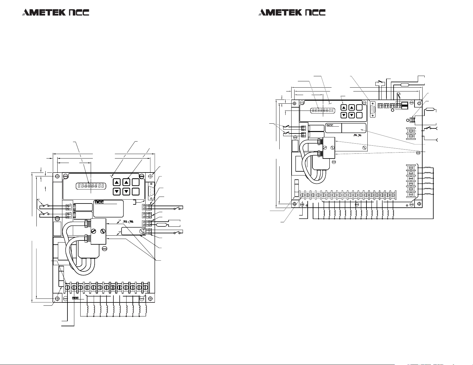
Models DNC-T2310-A10, B10, A220, & B220 Mounting and Wiring Details
VACUUM FLUORESCENT
DISPLAY (8 CHAR.)
(16 SEGMENT)
.312 (7.9)
AUX.
ALARM
INPUTS
SWITCH CLOSURE
INITIATES ALARM
STATUS
(NOT AVAIL. ON
B10 UNITS).
8.75 (222.3)
8.25 (209.5)
#8 SCREW
TERM. 13 PL.
.25
(6.35)
.65
(16.5)
DO NOT USE SLOW-BLOW OR LARGER SIZE
FAILURE TO COMPLY WILL VOID ANY
3AMP
WARRANTY
2.275
(57.8)
INPUT
ALARMALARM
INPUT
32
6.875 (174.6)
6.250 (158.7)
DIFFERENTIAL PRESSURE (d P)
INCHES OF WATER
1725 Western Dr.
ALARM
West Chicago, IL. 60185
INPUT
INTELLIGENT DUST CONTROL
2
MODEL NO.: DNC-T2310-✻✻✻✻
INPUT VOLTAGE:✻✻✻ VAC, 10VA
ALARM
INPUT
S/N:
3
ITEM VALUE
National Controls
Corporation
Date Code:
PRESSURE CONNECTIONS:
HI SIDE
LOW SIDE
POLYESTER OVERLAY
OUTPUT
STEP
ALARM
CANCEL
RS232
CONNECTOR
BYPASS/
CYCLE DOWN
INPUT
(-)
P OUTPUT
D
4-20 mA
(+)
R
ALARM
R
OUTPUT
ALARM
INPUT
1
BUTTONPAD
.25 DIA MOUNTING HOLE
(4 PL.)
RS-232 9 CIRCUIT
MALE CONNECTOR
SEE FIGURE 5
2 POS. SCREW TERMINAL
(6 PL.)
DIFFERENTIAL PRESSURE
CYCLE BYPASS/
CYCLE DOWN INPUT
4-20mA OUTPUT
REMOTE ALARM OUTPUT
ALARM VOLTAGE
ALARM
SOURCE
AUXILIARY ALARM
INPUT
BLACK INK SCREENING
(ALUMINUM COVER)
USER HOOKUP
’’DIRTY AIR PLENUM
& CLEAN AIR PLENUM"
PRESSURE CONNECTIONS
1/8-27 NPT TAPPED HOLE
TUBING FITTING
(2 PL.)
The controller's chassis is pre-drilled to mount directly inside
the NEMA housing. If the unit is going to be mounted inside
another enclosure, use the installation drawings that are shown
in Figures 1 & 2.
Models DNC-T2320-A10, B10, A220, & B220 Mounting and Wiring Details
VACUUM FLUORESCENT
DISPLAY (8 CHAR.)
(16 SEGMENT)
.25 (6.35)
AUX ALARM
INPUTS SWITCH
CLOSURE INITIATES
ALARM STATUS
(NOT AVAILABLE
ON ’-B10’ UNITS
250V 3 AMP
FUSE FOR 120VAC UNITS
(250V 1-1/2 AMP
FUSE FOR 240VAC UNITS)
#6 SCREW TERM.
(26 PL.)
POLYESTER OVERLAY
.59
(15.0)
.312 (7.92)
8.875 (225.4)
8.25 (209.5)
2.325
(59.0)
A
B2
A
B
FAILURE TO COMPLY WILL VOID ANY
DO NOT USE SLOW-BLOW OR LARGER SIZE
3AMP
WARRANTY
L1
L1
L2
RS-232 9 CIRCUIT
MALE CONNECTOR
SEE FIGURE 5
10.75 (273.0)
10.250 (260.35)
DIFFERENTIAL PRESSURE (d P)
INCHES OF WATER
ALARM
National Controls
INPUT
Corporation
1725 Western Dr.
West Chicago, IL. 60185
ALARM
INPUT
3
SOLL2 SOL 1 2 3 4
COM COM
DIRTY AIR PLENUM
CONNECTION
CLEAN AIR PLENUM
CONNECTION
20 -OUTPUTS TO 120 VAC SOLENOID AIR-VALVES
SOL. COM. TERMINALS ARE INTERNALLY CONNECTED TO L2 TERMINAL
DIFFERENTIAL PRESSURE
BUTTON PAD
OUTPUT
ITEM VALUE
ALARM
CANCEL
INTELLIGENT DUST CONTROL
MODEL NO.: DNC-T2320-A10
INPUT VOLTAGE:120 VAC, 10VA
S/N:RDate Code:
C
R
BYPASS/CYCLE DOWN
STEP
8567 9101112 13 14
4-20mA OUTPUT
ALARM
REMOTE ALARM
CONDITION
BYPASS/
RS232
CYCLE DOWN
INPUT
OUTPUTS
INPUT
ALARM
4-20mA
OUTPUT
-
+
ALARM
INPUT 1
REMOTE ALARM
CONDITION OUTPUT
(ALARM VOLTAGE
SOURCE)
.25 DIA. MOUNTING
HOLE (4 PL.)
2 POS. SCREW TERMINAL
(7 PL.)
ALARM
AUX OUTPUT FOR EXPANDED
MODE OR AUX REMOTE ALARM
AUX
CONDITION OUTPUT
OUTPUT
#4
(ALARM VOLTAGE SOURCE)
AUX
120VAC, 50/60HZ
INPUT
#4
(240VAC, 50/60HZ
120VAC
ON 240VAC UNITS)
BLACK INK SCREENING
(ALUMINUM COVER)
USER HOOKUP
’DIRTY AIR PLENUM’
AND ’CLEAN AIR PLENUM’
PRESSURE CONNECTIONS
TAPPED 1/8-27 NPT (2 PL.)
20
19
18
17
16
15
Figure 2
THESE CONTROLLERS ARE NOT DESIGNED TO BE INSTALLED
IN HARSH ENVIRONMENTS WITHOUT SUITABLE
PROTECTION. IMPROPER INSTALLATION WILL VOID THE
WARRANTY.
DO NOT:
L1
L2
AUX INPUT FOR
ALARM OR
EXPANDED MODE
213
456798
OUTPUTS
10
FIGURE 1
Figure 1
250V 3 AMP
FUSE FOR 120 VAC UNITS
250V 1.5 AMP
FUSE FOR 240 VAC UNITS
L1
L2
L2L1
SOL
COM
National Controls
Corporation
10 -OUTPUTS TO 120 or 240 VAC SOLENOID AIR-VALVES (DEPENDING ON MODEL)
SOL .COM. TERMINAL IS INTERNALLY CONNECTED TO L2 TERMINAL
T2310 / T2320 Operation Manual Page 6
Install this unit in an area of high vibration.
Install this unit close to strong magnetic fields.
T2310 / T2320 Operation Manual Page 7

National Controls Corp.
National Controls Corp. National Controls Corp.
Phone 800-323-2593 ● Fax 6 30-231-1377 ● Internet www.natcon.com
Phone 800-323-2593 ● Fax 6 30-231-1377 ● Internet www.natcon.com
National Controls Corp.
Phone 800-323-2593
Phone 800-323-2593 ● Fax 630-231-1377 ● Internet www.natcon.com
● Fax 630-231-1377 ● Internet www.natcon.com
2.0 ELECTRICAL HOOKUP
NOTE: To aid in installation, refer to the corresponding wiring diagram.
Connect this unit to the correct power source, which is listed
on the nameplate. Do not connect this unit to a "converter" or
"inverter" type power source. This unit should be installed on
its own 15-amp circuit. Do not connect this unit to a power
source that is subjected to large switched loads, such as, electric
motors, compressors, electric tools, etc.
WARNING: MAKE SURE THAT THE CIRCUIT THAT YOU ARE
WORKING WITH, IS "TURNED OFF", BEFORE YOU MAKE
THESE CONNECTIONS. SERIOUS INJURY MAY RESULT IF YOU
DO NOT TAKE THE PROPER SAFETY PRECAUTIONS.
On 120 volt models connect the "hot" or "high side" of the
incoming power source to "L1" on the terminal strip. Connect
the "return" to "L2" on the terminal strip.
On 220-volt models, connect one side of the 220-volt line to L1
and connect the other side of the 220-volt line to L2.
Connect the solenoid air valves to the terminal strip. These are
labeled with the word "OUTPUTS" and they are numbered 1
through 10 for the T2310 unit and 1 through 20 for the T2320
unit. You can connect more than one solenoid on each output,
as long as you do not exceed the 200VA (Watt) rating on each
output.
The return wires "commons" from the solenoids will return to
the "SOL COM" connection on the terminal strip.
3.0 ALARM INPUT CONNECTION
CAUTION: DO NOT APPLY ANY TYPE OF LIVE POWER TO
THIS ALARM INPUT. SEVERE DAMAGE TO THE UNIT WILL
OCCUR.
It is recommended that you do not run this wiring in conduit
or cabling raceways, which have high voltage or high current
conductors. It is also recommended that you use a twisted wire
pair for this connection.
3.2 T2320 Models:
There are 4 general-purpose alarm inputs on the DNCT2320-A10 and -A220 controllers. The DNC-T2320-B10 and
-B220 controllers which have the Real Time Clock installed, do
not have alarm inputs #2 and #3 available.
Alarm inputs 1, 2, and 3 will accept any type of sensor, which
has a "normally open, dry contact" switch output. The switch
or contact closure must be suitable for, 24VDC at .010 amps.
A switch or contact closure will indicate an alarm condition to
the controller.
CAUTION: DO NOT APPLY ANY TYPE OF LIVE POWER TO
ALARM INPUTS #1,2, OR 3. SEVERE DAMAGE TO THE UNIT
WILL OCCUR.
"ALARM AUX INPUT #4" is a dual-purpose input. It can
be used as a general alarm input or as the input for the
"EXPANDED MODE" feature, which is described in Expanded
Mode Section. As an alarm input, it requires a switched line
voltage input, 120VAC 50/60 Hz source for the -A10 and -B10
models and 220VAC 50/60 Hz source for the -A220 and -B220
models.
3.1 T2310 Models:
There are three general "ALARM INPUT" connections on the
DNC-T2310-A10 / A220 models and one general "ALARM
INPUT" on the DNC-T2310-B10 / B220. You can connect any
type of sensor to these inputs, which has a "normally open, dry
contact" switch output. The switch or contact on your equipment must be suitable for, 24VDC at .010 amps. A switch or
contact closure will indicate an alarm condition to the controller
T2310 / T2320 Operation Manual Page 8
CAUTION: DO NOT APPLY ANY OTHER VOLTAGE EXCEPT
AS SPECIFIED ABOVE, TO THIS INPUT. DAMAGE TO THE
CONTROLLER WILL OCCUR.
It is recommended that you do not run this wiring in conduit or
cabling raceways, which have high voltage or high current conductors.
It is also recommended that you use a twisted wire pair for this
connection.
T2310 / T2320 Operation Manual Page 9

National Controls Corp.
National Controls Corp. National Controls Corp.
Phone 800-323-2593 ● Fax 6 30-231-1377 ● Internet www.natcon.com
Phone 800-323-2593 ● Fax 6 30-231-1377 ● Internet www.natcon.com
National Controls Corp.
Phone 800-323-2593
Phone 800-323-2593 ● Fax 630-231-1377 ● Internet www.natcon.com
● Fax 630-231-1377 ● Internet www.natcon.com
4.0 ALARM OUTPUT CONNECTION
The "ALARM OUTPUT" connection is used to indicate to a
remote location that an alarm has occurred. All alarms that are
generated by the controller, including ALARM INPUTS #1, 2,
and 3, will activate this output.
This output is a set of "normally open" relay contacts. It is
capable of switching 3 amps at 120/240 VAC. When the controller has an alarm condition, the contacts will close.
The AUX INPUT #4 only controls the AUX OUTPUT #4 on the
T2320 models only. No other alarms will activate this output.
The relay contacts have the same rating as the output for
alarms #1, 2, and 3. A red LED located next to the alarm output
will light when the relay contacts are closed.
It is recommended that you do not run this wiring in conductor
cabling raceways, which have high voltage or high current
conductors. It is also recommended that you use a twisted pair
wire combination for this connection.
5.0 BYPASS/CYCLE DOWN INPUT CONNECTION
5.1 CYCLE DOWN MODE:
The Cycle Down mode allows the user to connect an auxiliary
set of contacts from the ventilation fan in the dust collector to
the Bypass/Cycle Down Input of the “Intelligent” controller in
order to clean the filters “off-line” when the fan shuts down.
If the Cycle Down mode is enabled, normal operation of the
controller occurs when the Bypass/Cycle Down Input is shorted; opening the Bypass/Cycle Down Input will begin a "POWER
CYCLE DELAY" time and will inhibit any cleaning cycles due
to the differential pressure. The display will alternate the words
"POWER", "CYCLE", "DELAY" and "∆P =XX.X".
At the end of this delay, the unit will cycle through all the
selected outputs as determined by the number of cycles selected with the "NO_ CYL XX" programming menu item, beginning
at output number 1. If the unit is being used in expanded
mode, the cleaning cycle of the Cycle Down mode will start
on the external board. When the Bypass/Cycle Down Input is
closed, the unit shall resume normal operation.
5.2 BYPASS MODE:
If the Bypass/Cycle Down Input is shorted with the Cycle Down
mode disabled, a cleaning cycle shall be initiated regardless of
the value of the sensed pressure and will continue until the
circuit is opened. Once the input is opened the cleaning cycle
will either stop or continue based on the value of the sensed
pressure as previously defined.
CAUTION: DO NOT APPLY ANY TYPE OF LIVE POWER TO
THIS BYPASS/CYCLE DOWN INPUT. SEVERE DAMAGE TO THE
UNIT WILL OCCUR.
NOTE: The "ALARM INPUTS", "ALARM OUTPUT", and "BYPASS/CYCLE
DOWN INPUT" do not need to be connected for the operation of the
controller. These connections are optional.
6.0 PRESSURE CONNECTIONS
The controller is equipped with a metal manifold, which is used
to make the differential pressure connections. The manifold is
tapped for 1/8-27 NPT, female pipe fitting.
It is recommended that the tubing be run through a bulkhead
fitting on the NEMA enclosure. This will provide a seal to prevent moisture, dust and particulates from entering the enclosure.
Connect the "HIGH SIDE" or “dirty air” pressure connection
to the inlet of the dust collector. Do not make sharp bends
or kink the tubing when installing. Follow the manufacturers'
installation instructions for the placement of the input pressure
tubing.
CAUTION: THE MAXIMUM PRESSURE THAT CAN BE APPLIED
TO THE PRESSURE INPUTS IS 10 PSI. ANY GREATER
APPLIED PRESSURE, EVEN MOMENTARILY, WILL DAMAGE
THE PRESSURE SENSOR.
Connect the "LOW SIDE" or “clean air” pressure connection
to the outlet of the dust collector. Do not make sharp bends
or kink the tubing when installing. Follow the manufacturers'
installation instructions for the placement of the output pressure tubing.
T2310 / T2320 Operation Manual Page 10
T2310 / T2320 Operation Manual Page 11

National Controls Corp.
National Controls Corp. National Controls Corp.
Phone 800-323-2593 ● Fax 6 30-231-1377 ● Internet www.natcon.com
Phone 800-323-2593 ● Fax 6 30-231-1377 ● Internet www.natcon.com
National Controls Corp.
Phone 800-323-2593
Phone 800-323-2593 ● Fax 630-231-1377 ● Internet www.natcon.com
● Fax 630-231-1377 ● Internet www.natcon.com
7.0 4 TO 20 MILLIAMP CURRENT LOOP
The "4-20mA" output is used for a remote indication of differential pressure. Zero inches of differential pressure will produce
4 milliamps at this output; fifteen inches of differential pressure
will produce 20 milliamps.
There is a plus (+) and minus (-) connection for this output.
Make sure that you observe the polarities when you make the
connections to your equipment.
It is recommended that you do not run this wiring in conductor
cabling raceways, which have high voltage or high current
conductors. It is also recommended that you a twisted pair wire
combination for this connection.
8.0 BEFORE APPLYING POWER TO THE UNIT
■ Recheck all of your electrical connections.
■ Recheck all of your mechanical and pressure
connections.
■ Turn on the circuit breaker.
■ Observe the display on the controller, the word "SETUP" should be on
the display. If not, ignore the message on the display.
9.0 TROUBLESHOOTING
If the display does not show a message after the application of
power, check the following:
■ Check the wiring from the circuit breaker to L1 and L2 on the
controller.
■ Check the fuse on the controller. A blown fuse on the controller
may indicate a problem with the solenoid outputs. Recheck the
connections to the solenoids.
■ A short in the solenoid wiring or a short in a solenoid itself may
not cause the fuse to blow during setup of the controller. If there
is a problem with an output, the fuse may blow during the auto
configuration of the outputs or during the first cleaning cycle.
■ Verify that the correct circuit breaker was turned on.
CAUTION: THE FUSE THAT IS INSTALLED ON THE
CONTROLLER IS A FAST-BLOW FUSE. DO NOT USE A SLOWBLOW OR A LARGER SIZE FUSE. FAILURE TO COMPLY WILL
VOID ANY WARRANTY.
10.0 "SETUP" MODE
After the application of power to a new controller, the word
"SETUP" should be on the display. The controller is shipped
in this mode so that all the programmable parameters are
reviewed before the system is placed in operation.
If you see the message "∆P =xx.x", which is the current differential pressure, this may indicate that the unit has been
previously configured. If you do not have the "SETUP" mode
message and you want to reset the controller to this mode refer
to the section for Reloading Factory Defaults for instructions.
11.0 FACTORY DEFAULT SETTINGS
■ Solenoid output selction:..................................................................................Manual
■ Last solenoid:..…….........................................................................................................10
■ Low pressure setting:...................................................................2.0 inches of water
■ High pressure setting:.................................................................4.0 inches of water
■ Solenoid on time:.......................................................................................0.10 seconds
■ Solenoid off time............................................................................................15 seconds
■ High alarm pressure:.................................................................14.0 inches of water
■ Cycle Down:....................................................................................................................NO
■ Number of Cycles:.............................................................................................................2
12.0 USING THE "ITEM" UP AND DOWN ARROW BUTTONS
By pressing the up or down "ITEM" buttons, you can display
the different messages that are available. The following are two
lists of the display messages as they would appear on your
controller when the unit is in the "SETUP" mode or in the
"OPERATING" mode.
T2310 / T2320 Operation Manual Page 12
T2310 / T2320 Operation Manual Page 13
 Loading...