

NATIONAL CONTROLS DNC-T2310 User Manual
4-14
DUST COLLECTOR CONTROLS
Intelligent, AC-Input, Pulse Cleaning
of Bag House Dust Collectors
Models DNC-T2310 and DNC-T2320
FEATURES
On-board differential pressure sensor
●
4 - 20 mA output for DP
●
8 character alpha-numeric display
●
Microprocessor based control for stable
●
timing from -40°C to 65°C
Enhanced timer option: monitor addi
●
tional devices; record dust collector
data; network timers together remote
network monitor; remote network con
trol
RS232 port for remote monitor and con
●
trol
Automatic output setup capability
●
Expanded cycle mode allows additional
●
dust collector controllers to expand out
put capabilities
High pressure alarm indication
●
Output fault detection
●
Alarm output contacts
●
●
Alarm input sensors
●
Pulse time: line synchronized to elimi
nate 8 ms triac turn off variation per
output
10 A 400 V output triacs for maximum
●
protection against output shorts; 200 VA
load rating
Conformally coated for protection
●
against vibration, humidity, and con
tamination
Metal chassis provided: for mounting
●
directly into nema 4 box
Timer functionally tested to eliminate
●
field failures
Input protection: 30 joule metal oxide
●
varistor
One year warranty: warranted to be
●
free from defects in materials or work
manship for one year from date of man
ufacture
●
Models T2310 and T2320 are microprocessor-based bag house filter controllers
which combine a ten or twenty output
sequencer with a solid state differential
pressure sensor. This offers a small, lowcost replacement to the separate solid state
sequencer and pressure gauge combination
most often used in on-demand pulse jet
cleaning systems. These controllers will
sense the pressure difference across the
filters of a bag house and initiate a cleaning
File #E65038
-
-
-
-
-
cycle when the filters start to impede the air
flow. When the pressure drops to normal the
controller will stop cycling.
Standard Operating Logic: The timers can
operate in the following modes:
●
Auto output: only configured outputs will
be pulsed. Output faults will be detected
and indicated.
●
Manual output: outputs will recycle after
last output used.
●
Output step: a single cleaning pulse can
-
be initiated by pressing the output step
key regardless of pressure input.
●
Continuous cycle: controller will cycle
indefinitely when the bypass/cycle down
input is shorted.
-
●
Cycle down: the outputs will be pulsed
through a user seleced number of com
plete cycles when the bypass/cycle down
input is shorted. This cycle will occur
regardless of pressure input.
Expanded output mode: controller will
●
cycle to output #10 or #20, then will ini
tiate an extended output mode via the
alarm input and output terminals to
NCC’s DNC-T2000 series dust collec
tor controllers. This will facilitate sys
tems which require greater than 10 or 20
outputs.
Standard Timer Operation Status
Indication: The Timer can show the follow-
ing information on its 8-character alphanumeric display during normal operation:
●
DP from 0” to 15” water column
●
High or Low DP Alarms
●
Solenoid Fault Conditions
●
Current Output being Pulsed
●
-
Auxiliary Alarm Input Closures
Upon occurance of any alarm event, the
alarm status is reported on the display
along with the output number that was
pulsed during the time of the event.
●
Alarm Outputs: The isolated Alarm
Output contacts will close for alarm
conditions such as output faults,
high pressure alarm, warm-up failure,
etc. During an alarm condition, a
corresponding message is displayed.
●
Alarm Input: A closure across the Alarm
Input terminals will be indicated on
the display as well as initiate the Alarm
Output.
In addition to the standard operation of the T2310 and T2320,
an enhanced operation option
-
is available with the use of the
DNC-T2300-I/O Remote Input/
Output module in conjunction
with the DNC-T2300-DSP Remote
Annunciator Panel. The T2310
-
and T2320 Timers along with the
DNC-T2300-I/O constitutes the
-
-
Enhanced Timer system which
allows the user to monitor and
record the data parameters associ
ated with a dust collector system.
This system can range in size from
1 to 255 dust collectors, all report
ing to a central location, the DNCT2300-DSP.
Enhanced Timer Operation
Status Indication: The Timer can
show the following information on
its 8 character alpha-numeric dis
play during normal operation:
DP from 0” to 15” water column
●
●
High or Low DP Alarms
●
Solenoid Fault Conditions
●
Current Output being Pulsed
●
Auxiliary Alarm Input Closures
●
DNC-T2300-I/O Analog Input
Status
DNC-T2300-I/O Alarm Input
●
Closures
Upon occurance of any alarm
event, the alarm status is reported
on the display along with the out
put number that was pulsed during
the time of the event.
-
-
-
-
AMETEK National Controls Corp. • 1725 Western Drive • West Chicago, Illinois 60185 • Tel: 800-323-2593 • 630-231-5900 • FAX: 630-231-1377 • www.nationalcontrols.com
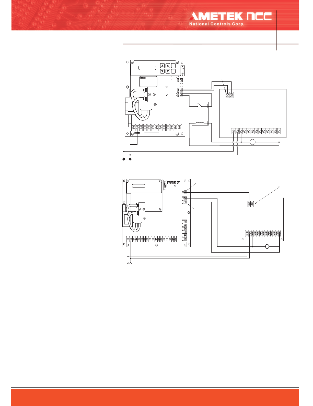
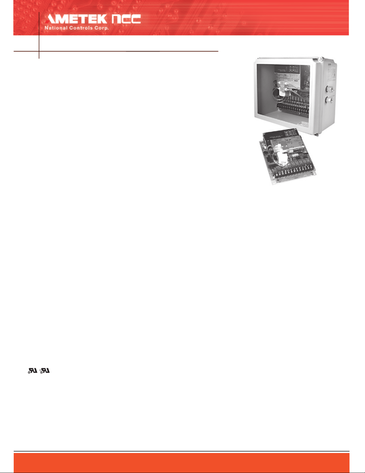
CL1L2 1 32 94 65 7 8 10
S
LAST SOLENOID
EXPANDED MODE WIRING DIAGRAM FOR DNC-T2320-*10
PRESSURE SWITCH
DNC SERIES DUST
COLLECTOR CONTROLLER
DNC-T2010 MODEL SHOWN
(EXCEPT T2310)
L1
L2
AUX OUTPUT
#4
AUX INPUT
#4
-T2320-
INPUT VOLTAGE 120 VAC
RS232 Port:
FAILURE TO COMPLY WILL VOID ANY
WARRANTY
DO NOT USE SLOW-BLOW OR LARGER SIZE
Model DNC-T2310-010
SOL
COM
L1 L2
3AMP
1
2 3 4
OUTPUTS
5 6
7 8109
HI SIDE
CONNECTIONS:
PRESSURE
LOW SIDE
1725 Western Dr.
S/N:
INTELLIGENT DUST CONTROL
West Chicago, IL. 60185
INPUT VOLTAGE:120 VAC, 10VA
MODEL NO.: DNC-T2310-010
Date Code:
BYPASS
INPU
T
ALARM
OUTPUT
ALARM
INPUT
INCHES OF WATER
DIFFERENTIAL PRESSURE ( P)
National Controls
Corporatio
n
D
OUTPUT
STEP
CANCE
L
ALARM
CONNECTOR
RS232
ITEM VALUE
National Controls
Corporation
S
Last solenoid
DNC-T2003 Through
DNC-T2032 Series
Dust Collector Controller
(DNC-T2010 model shown)
C
10987654321L2
L1
PRESSURE SWITCH INPUT
N
O
. .
CO
I
L
120 VAC Coil
SPST-NO
Relay
EXPANDED MODE WIRING DIAGRAM FOR DNC-T2310-*10
INPUT VOLTAGE 120 VAC
Remote Terminal: An ANSI type ter
●
minal is required for remote monitor
ing and programming of the controller.
Connection to the controller is made via
the RS232 port (9 pin D-Sub connec
tor). All the functions and display status
accessible from the controller are avail
able through the ANSI terminal.
Remote I/O Interface: The 2310/2320
●
controllers are capable of communication
with the DNC-T2300-I/O board via the
RS232 port. This allows the user to moni
tor up to three 4-20 mA analog inputs,
three contact closure type inputs, and
one Type J thermocouple. The I/O mod
ule is programmed via the 2310/2320
keypad and can be user defined to set
alarm points from remote sensors of
parameters such as emission, air flow,
pressure, broken bags, fan motor current,
etc. Refer to the data sheet for the DNCT2300-I/O for additional information.
DUST COLLECTOR CONTROLS
4-15
-
-
-
-
-
-
Programming Logic: The controller as sup
plied from the factory will require user con
-
figuration. Upon application of power the
display will indicate SETUP. The operator
must then configure the various operating
parameters using the six key keyboard of
the controller before normal cleaning opera
tion can begin. The programmable param
-
eters for Standard Operation as displayed
are:
OUTPUT
●
Auto Configuration: will automatically
sense the solenoids connected to the
outputs and will only pulse those outputs
during cleaning cycles.
Manual Configuration: the controller will
pulse each output until the last output
programmed and then recycle to output
For enhanced timer programming information, see IDC Programming Tree on page
4-6.
#1.
LAST: the number of the last output
●
used.
AMETEK National Controls Corp. • 1725 Western Drive • West Chicago, Illinois 60185 • Tel: 800-323-2593 • 630-231-5900 • FAX: 630-231-1377 • www.nationalcontrols.com
LO DP: Low Pressure Setpoint, the pres
●
sure at which the controller will stop its
cleaning cycle.
HI DP: High Pressure Setpoint, the pres
●
sure at which the controller will start its
cleaning cycle.
ON: Output Solenoid On Time.
●
OFF: Off Delay Time Between Output
●
Solenoid Activation.
ALARM: High Differential Pressure Alarm
●
Set-point, the pressure at which the con
troller will close its alarm contacts.
Additional Features: The 2310/2320 con
trollers also provide:
-
-
provide a continuous reading from 4 -20
mA corresponding to the sensed differen
tial pressure range of 0” to 15” water col
umn. This is a standard feature.
24 Hour Time/Day/Month Clock: The
●
4 - 20 mA Output Loop: This output will
●
clock feature will allow a daily automat
ic turn on and turn off command to be
implemented by the controller. It can be
programmed to start and stop the clean
-
week. This is an optional feature found on
ing cycles for up to seven events per
the B-series models.
-
-
-
Caution:
1. Do not mount controls in high vibration areas with
out shock mounts.
2. Do not mount controls in areas of high dust or cor
-
rosive atmospheres without a protective enclosure.
3 Do not use a converter or inverter for the power
source.
4. Do not mount control in high transient voltage
-
areas without an isolation transformer.
5. Do not leave control box open.
6. Do not allow a local repair shop to repair the con
trols, as we employ some very sophisticated compo
nents that could be further damaged. For service, call
us directly: 800-323-2593.
-
-
-
-
 Loading...