

National TESSERA HGT. ADJ. DESK Assembly Instruction Manual
Proper product installation, in accordance with these instructions, is the responsibility of the installing agent.
If you have any questions concerning these instructions, please call National Customer Service 800.482.1717.
Assembly Instrucon
Telephone 800.482.1717
Fax 812.482.8800
www.NationalOfficeFurniture.com
3206401
Rev, -
TESSERA HGT. ADJ.
DESK
Tools Required
-Screw Driver w/ #2 Phillips Bit
-Level
-Cable ties
Hardware
-Glides x8
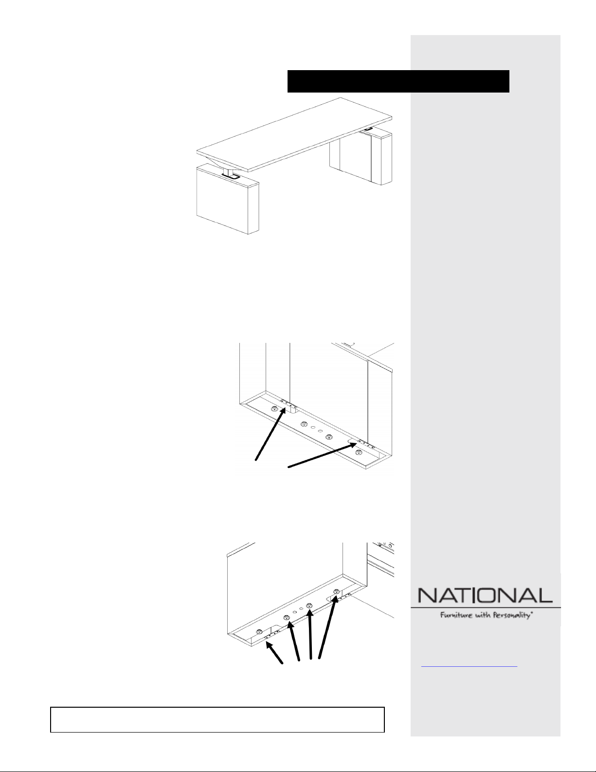
Figure A
1
Unpack the desk and set into posion.
Figure B
Figure C
3
Install glides (Qty. 4 per shroud) supplied in hardware kit to underside of each
shroud (Figure C)
2
Remove two at brackets from the boom of each shroud to access the interior as
needed. Brackets can be discarded (Figure B) as they are only installed to protect
during shipping.
NOTE: Removable panel hangs from Z-clip brackets. Once at brackets are
removed care should be taken so that the panel does not disengage from Z-clip
and damage the component.
Proper product installation, in accordance with these instructions, is the responsibility of the installing agent.
If you have any questions concerning these instructions, please call National Customer Service 800.482.1717.
Assembly Instrucon
Telephone 800.482.1717
Fax 812.482.8800
www.NationalOfficeFurniture.com
3206401
Rev, -
TESSERA HGT. ADJ.
DESK
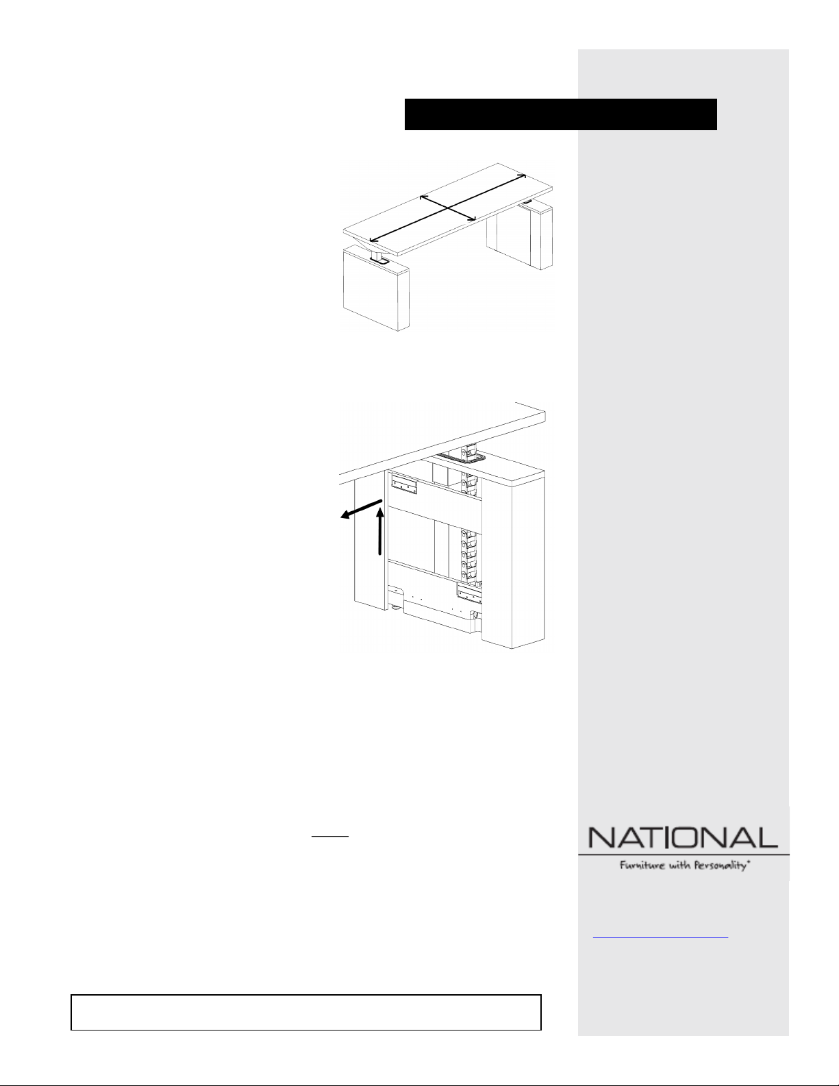
4
Posion desk in nal locaon and level the unit using the glides (Figure D).
Figure D
Figure E
6
The wire manager comes installed on the user’s right side shroud. If this is the
preferred locaon proceed to Step 7. If this isn't the preferred posion see the
Wire Manager Relocaon secon at the end of this instrucon to relocate it to the
le side shroud. Aer this relocaon procedure is complete proceed to Step 7.
5
The shroud’s interior panels can be removed to access the wire manger by pulling
up to clear the Z-clip then away to free the panel from the shroud (Figure E).
8
Replace removable panel back onto the shroud Z-clip hangers.
7
Run power and accessory lines through wire manager ensuring all leads run the full
length of the wire manager.
WARNING: Lines running to worksurface MUST be routed through the full length
of the wire manager to ensure enough lead length is available to support the
mechanism’s full range of moon.
9
Power up unit and review mechanism manual for recalibraon and usage.
 Loading...