

National PANTHER 5110 Instruction Manual

#5110 PANTHER
®
ELECTRIC RIDE-ON
FLOOR PREP SYSTEM
INSTRUCTION MANUAL
115 & 230 Volt
Read Manual Before Operating Machine
9250 XYLON AVENUE NORTH • MINNEAPOLIS, MN 55445 • U.S.A.
800-245-0267 • 763-535-8206 • FAX 763-535-8255 • FAX 800-648-7124
WEB SITE: www.nationalequipment.com • E-MAIL: info@nationalequipment.com
National
Flooring Equipment, Inc.

Page 2
5110 TABLE OF CONTENTS
Table of Contents ..................................................................................................2-4.1
Hydraulic ..................................................................................................................5-6
A. Maintaining A Safe Work Environment ................................................................5
B. Pressure............................................................................................................5-6
C. Flammability ........................................................................................................6
D. Hydraulic Fluid......................................................................................................6
Rules for Safe Operation........................................................................................7-10
A. Characteristics of a Defensive Operator ..........................................................8.1
B. Grounding ............................................................................................................9
C. Extension Cords ................................................................................................10
Safety Instructions ....................................................................................................11
Features/Specifications ....................................................................................12-12.1
Operating Controls ..............................................................................................13-15
A. Power Box..........................................................................................................13
B. Hydraulic Levers ................................................................................................13
C. Cylinder Lift ........................................................................................................14
D. Operating Around the Cord ................................................................................15
Operational Tips ........................................................................................................16
A. Caster ................................................................................................................16
B. Foot Peg ............................................................................................................16
C. Seat Safety Switch ............................................................................................16
D. Disarm Machine ................................................................................................16
E. Disconnect Machine From Power ......................................................................16
F. Leakage ............................................................................................................16
G. Power Cord ........................................................................................................16
H. Angle of the Head is Set Steep ..........................................................................16
How To Plug In Cords ..........................................................................................17-18
A. Size and Gage of Extension Cords ....................................................................17
B. Cord Hook-Up ....................................................................................................17
C. Outlet Testing ....................................................................................................18
D. Cord Length ......................................................................................................18
E. Circuit Breaker Troubleshooting ........................................................................18
F. Wall Receptacle Choice and Testing ..................................................................18
Loading/Unloading ..............................................................................................19-20
A. Dock Heights......................................................................................................19
B. Power-Gate ........................................................................................................19
C. Ramps................................................................................................................19

Page 3
5110 TABLE OF CONTENTS
D. Forklift Cups ......................................................................................................20
E. Winches..............................................................................................................20
F. Transporting ......................................................................................................20
G. Wheel Chocks ....................................................................................................20
Center of Gravity ....................................................................................................20.1
Job Site Movement ..............................................................................................21-22
A. Taping Wheels....................................................................................................21
B. Palletizing ..........................................................................................................21
C. Front Wheel Assembly ......................................................................................21
D. To Move Machine Without Power ......................................................................22
E. Adjusting Flip Arm Guide in Confined Area’s ....................................................22
Wheel Sizes ..............................................................................................................23
A. Wheel Size ........................................................................................................23
Adding Additional Weight ..........................................................................................24
A. Front Weight ......................................................................................................24
B. Rear Weight ......................................................................................................24
Cutting Head and Blade ......................................................................................25-26
A. Dialing in the Machine........................................................................................25
B. Saving Time with Extra Cutting Heads ..............................................................25
C. Adjusting Slide Plate and Cutting Head ............................................................25
D. Shear Point ........................................................................................................25
E. Weight vs. Sharpness ....................................................................................25.1
F. Cutting Head Angle ........................................................................................25.1
G. Steep Cutting Head Angle ..............................................................................25.1
H. Swivel Head ....................................................................................................25.1
I. Saving Time with Extra Cutting Heads............................................................25.1
J. Cutting Head Insertion ......................................................................................26
K. Shank Blade Insertion ........................................................................................26
L. Blade Setting......................................................................................................26
M. Self Scoring Blades............................................................................................26
N. Blade Insertion or Blade Changing ....................................................................26
Blade Application/Set-Up ..................................................................................27-28.1
A. Ceramic Set-Up..................................................................................................27
B. Wood Set-Up......................................................................................................27
C. Secondary Backing Carpet Set-Up ....................................................................27
D. Foam Back Carpet Set-Up ................................................................................27
E. Double Stick Carpet Set-Up ..............................................................................27
F. VCT Tile Set-Up ................................................................................................27

Page 4
5110 TABLE OF CONTENTS
G. Rubber Tile Set-Up ............................................................................................27
H. Re-Scraping Set-Up ..........................................................................................27
I. Thin Coating Set-Up ..........................................................................................28
J. Working Over Concrete......................................................................................28
K. Working Over Wood ..........................................................................................28
L. Working Over Soft Sub-Floor ............................................................................28
M. Cross Room Ditching ......................................................................................28.1
N. Checker Board Ditching ..................................................................................28.1
Blades ..............................................................................................................29-30.1
A. Types of Blades..................................................................................................29
B. Blade Sharpening............................................................................................29.1
C. Blade Selection Chart ................................................................................30-30.1
Machine Maintenance ......................................................................................31-38.1
A. Slide Plate Removal ..........................................................................................31
B. Lower Cutting Head Support..............................................................................31
C. Leak Maintenance..............................................................................................31
D. Side and Rear Panels ........................................................................................32
E. Oil Level ............................................................................................................32
F. Oil Change Out ..................................................................................................32
G. Wheel Motor Change Out ..................................................................................32
H. Hose Change Out ..............................................................................................33
I. Foot Peg ............................................................................................................33
J. Pump Change Out ............................................................................................33
K. Valve Change Out ..............................................................................................33
L. Motor Change Out..............................................................................................33
M. Motor Overload Switch ......................................................................................34
N. Electrical Box......................................................................................................34
O. Hydraulic Cylinder Change Out..........................................................................34
P. Electrical Cord ....................................................................................................34
Q. 110 Volt Wire Diagram ....................................................................................34.1
R. 230 Volt Wire Diagram ....................................................................................34.2
S. Cord Guide ........................................................................................................35
T. Wheel Changing ................................................................................................35
U. Changing Filter ..................................................................................................35
V. Caster Maintenance ..........................................................................................36
W. Back Up Beeper and Light ................................................................................37
X. Seat Replacement..............................................................................................38
Y. Seat Safety Switch ............................................................................................38
Z. Debris Deflector Mounting Instructions ..........................................................38.1

Page 4.1
5110 TABLE OF CONTENTS
Complete Parts List ..........................................................................................39-41.2
Part Numbers and Diagrams................................................................................42-55
A. Hood & External Parts........................................................................................42
B. Electrical Box Parts ............................................................................................43
C. Switch & Back-Up Beeper Parts ........................................................................44
D. Instruction Tube & Cord Parts ............................................................................45
E. Motor Parts ........................................................................................................46
F. Pump Parts ........................................................................................................47
G. Frame & Support Parts ......................................................................................48
H. Wheel Parts........................................................................................................49
I. Single Spool & Hose Parts ................................................................................50
J. Double Spool & Hose Parts................................................................................51
K. Slide Plate & Cylinder Parts ..............................................................................52
L. Caster & Foot Peg Parts ....................................................................................53
M. Filter Parts..........................................................................................................54
N. Weights. ............................................................................................................55
Labels ..................................................................................................................56-57
Accessories ..........................................................................................................58-60
Material Safety Data ............................................................................................61-66
Guarantee..................................................................................................................67
Return Sheet ............................................................................................................68
Blade Order Form ................................................................................................69-70

Page 5
MAINTAINING A SAFE WORK ENVIRONMENT
Establishing a safe working environment in and around your hydraulic equipment is just common sense.
The easiest and most effective way to avoid problems is to make sure associates understand their
equipment, know how to operate it safely and recognize the danger it represents if handled carelessly. A
few things you must be aware of include:
1. PRESSURE: Hydraulic fluid under pressure is dangerous and can cause serious injury.
2. FLAMMABILITY: When ignited, some hydraulic fluids can explode and/or cause fires.
3. MECHANICAL: Hydraulic fluid creates movement, which causes parts of your equipment to move or
rotate. Always be aware of what you are doing.
4. MOISTURE: Never operate in wet or high moisture conditions without a proper GFI grounded switch.
Make sure all electrical fittings, switches, cords plus stain reliefs are in good condition. Always unplug
when not in use and when doing any service work.
5. ELECTRICAL: Disconnect power before servicing. Unplug cord so it can’t be started. Faulty wiring
can also be an electrical hazard. A regular preventive maintenance program should always include a
wiring check.
6. TEMPERATURE: Because this machine operates at a relatively low pressure, overheating is not
common. If surface of tank becomes too hot to touch by hand (above 130º), shut off machine and
allow to cool off.
PRESSURE
Our system runs at or below 1,200 psi. Never look for a leak when unit is under pressure. Using your
hand could cause serious injury. A few common ways to encounter hydraulic fluid under pressure include:
1. PINHOLE: Fluid under pressure can cause serious injury. It can be almost invisible escaping from a
pinhole, and it can pierce the skin into the body. Do not touch a pressurized hydraulic hose
assembly with any part of your body. If fluid punctures the skin, even if no pain is felt, a serious
emergency exists. Obtain medical assistance immediately. Failure to do so can result in loss of the
injured part or death.
2. LEAK: Keep fittings and hoses tight. Only check and service when not under pressure. Leaking
hydraulic fluid is not only unsightly, it’s hazardous. In addition to making workplace floors slippery and
dangerous, leaks also contaminate the environment. Before cleaning an oil spill, always check EPA,
state and local regulations.
LEAK AT THREAD END/SEAT
Problem: Coupling leaks at thread or seat. This may be caused by any of the following:
a. Missing or damaged O -rings.
b. Damaged threads or seat angle.
c. Thread alignment.
d. Incompatible thread ends or seat angles.
e. Over or undertorquing.
Solution: Remove the connection and inspect.
1. Certain couplings require the use of an O-ring. If it is missing, replace it. If an O-ring is used,
check for damage caused by installation or possible material breakdown from heat or fluid
incompatibility. Alternative O-ring materials may be required. Replace if necessary.
HYDRAULIC SAFE OPERATION

Page 6
HYDRAULIC SAFE OPERATION
PRESSURE (continued)
2. Check the threads and/or seat angle for damage that may have occurred prior to or during
installation. Any ding or burr may be a potential leak path. Replace if necessary.
3. If the coupling was misaligned during installation, threads may have been damaged. Replace
and carefully install.
4. Overtorquing of a threaded connection can stretch and damage threads and mating seat angles.
Overtorquing can also damage the staking area of the nut. Undertorquing does not allow
proper sealing.
3. BURST: Whether due to improper selection or damage, a ruptured hose can cause injury. If it bursts,
a worker can be burned, cut, injected or may slip and fall.
4. COUPLING BLOW-OFF: If the assembly is not properly made or installed, the coupling could come
off and hit or spray a worker, possibly resulting in serious injury. Never operate machine without
guards.
FLAMMABILITY
With the exception of those comprised primarily of water, all hydraulic fluid is flammable when exposed to
the proper conditions (including many “fire-resistant” hydraulic fluids).
Leaking pressurized hydraulic fluids may develop a mist or fine spray that can flash or explode upon contact
with a cause of ignition. These explosions can be very severe and could result in serious injury or death.
Precautions should be taken to eliminate all ignition sources from contact with escaping fluids, sprays or
mists resulting from hydraulic failures. Sources of ignition could be electrical discharges (sparks), open
flames, extremely high temperatures, sparks caused by metal -to -metal contact, etc.
HYDRAULIC FLUID
Only use Texaco Rando 46 Hydraulic Oil or Compatible Fluid Like IS032. Non-compatible fluids could
cause damage to unit or serious injury.
CAUTION: Never check for leaks over hose or hydraulic connections. Instead, use a piece of
cardboard to locate a pressurized leak. For drips (low pressure leaks), use a rag to clean the area and
determine where the leak originates.
CAUTION: Never touch a pressurized hose assembly. Shut down the hydraulic system before
checking hose temperature.
WARNING: When using electric tools, always follow basic safety precautions to reduce the risk
of electric shock and personal injury.

Page 7
RULES FOR SAFE OPERATION
READ AND SAVE ALL INSTRUCTIONS FOR FUTURE USE. Before use, be sure everyone
operating this equipment reads and understands this manual as well as any labels packaged with or
attached to the machine and components and view the instruction video. Extra copies of the manual and
video are available.
1. KNOW YOUR EQUIPMENT: Read this manual and view instruction video carefully to learn
equipment applications and limitations as well as potential hazards associated with this type of
equipment.
2. DISARM MACHINE: Remove cutting head or drop cutting head to the floor when machine is not
in use.
3. DO NOT “SLIDE HILL” MACHINE: See Page 19.
4. GROUND YOUR TOOL: See Grounding (Page 9).
5. AVOID DANGEROUS ENVIRONMENTS: Do not use in rain, damp or wet locations, or in the
presence of explosive atmospheres (gaseous fumes, dust or flammable materials). Remove materials
or debris that may be ignited by sparks.
6. KEEP WORK AREA CLEAN AND WELL LIT: Cluttered, dark work areas invite accidents.
7. DRESS PROPERLY: Do not wear loose clothing. These may be caught in moving parts. Keep hands
and gloves away from moving parts.
8. USE SAFETY EQUIPMENT: Everyone in the work area should wear safety goggles or glasses
complying with current safety standards. Wear hearing protection during extended use and a dust
mask for dusty operations. Hard hats, face shields, safety shoes, etc. should be worn when specified
or necessary.
9. KEEP BYSTANDERS AWAY: Children and bystanders should be kept at a safe distance from the
work area to avoid distracting the operator and contacting the tool or extension cord. Operator should
be aware of who is around them and their proximity.
10. PROTECT OTHERS IN THE WORK AREA: Provide barriers or shields as needed to protect others
from debris and machine operation.
11. USE PROPER ACCESSORIES: Using accessories that are not recommended may be hazardous.
Be sure accessories are properly installed and maintained. Do not delete a guard or other safety
device when installing an accessory, attachment or servicing.
12. CHECK FOR DAMAGED PARTS: Inspect guards and other parts before use. Check for
misalignment, binding of moving parts, improper mounting, broken parts and any other conditions that
may affect operation. If abnormal noise or vibration occurs, turn the tool off immediately and have the
problem corrected before further use. Do not use damaged equipment. Tag damaged tools “DO NOT
USE” until repaired. A guard or other damaged parts should be properly repaired or replaced. For all
repairs, insist on only identical National replacement parts.
13. REMOVE ALL ADJUSTING KEYS AND WRENCHES: Make a habit of checking that the adjusting
keys, wrenches, etc. are removed from the tool before turning it on.
WARNING: Disarm machine when not in use. Remove Cutting Head or lower Cutting Head to
the floor. When exiting machine (getting off machine), remove lower Cutting Head to the floor. When
transporting machine around job site, remove Cutting Head. Failure to follow these instructions could
cause severe bodily injury.

Page 8
RULES FOR SAFE OPERATION
14. GUARD AGAINST ELECTRIC SHOCK: Prevent body contact with grounded surfaces such as pipes,
radiators, ranges and refrigerators. When scoring or making cuts, always check the work area for
hidden wires or pipes. Use a Ground Fault Circuit Interrupter (GFCI) to reduce shock hazards.
15. AVOID ACCIDENTAL STARTING: Be sure equipment is turned off before plugging it in. Do not use
if the power switch does not turn the machine on and off.
16. DO NOT FORCE EQUIPMENT: Equipment will perform best at the rate for which it was designed.
Excessive force only causes operator fatigue, increased wear and reduced control.
17. KEEP HANDS AND FEET AWAY FROM ALL CUTTING EDGES AND MOVING PARTS.
18. WEAR GLOVES WHEN CHANGING BLADES.
19. DO NOT ABUSE CORD: Never unplug by yanking the cord from the outlet. Pull plug rather than cord
to reduce the risk of damage. Keep the cord away from heat, oil, sharp objects, cutting edges and
moving parts.
20. DO NOT OVERREACH. MAINTAIN CONTROL: Stay properly seated. Keep proper footing and
balance at all times. Maintain a firm grip.
21. STAY ALERT: Watch what you are doing, and use common sense. Do not use when you are tired,
distracted or under the influence of drugs, alcohol or any medication causing decreased control.
22. STARTING MACHINE: On/off switch must be in off position before connecting to power source.
23. UNPLUG EQUIPMENT: When it is not in use, unplug tool before changing blades, accessories or
performing recommended maintenance or when not in use.
24. MAINTAIN EQUIPMENT CAREFULLY: Keep control levers dry, clean and free from oil and grease.
Keep cutting edges sharp and clean. Follow instructions for lubricating and changing accessories.
Periodically inspect all wiring and extension cords for damage. Have damaged parts repaired
or replaced.
25. STORE IDLE EQUIPMENT: When not in use, store in a dry, secured place. Keep away
from children. Remove blade or keep blade lowered to the floor (disarm machine).
26. MAINTAIN LABELS AND NAMEPLATES: These carry important information. If unreadable or
missing, contact National for a free replacement.
27. MACHINE IS HEAVY, DO NOT DROP: Counter weights are heavy. Take caution when removing
or reassembling. Take caution when moving or transporting.
28. IF THE SUPPLY CORD IS DAMAGED: It must be replaced by the manufacturer or its service agent
or a similarly qualified person in order to avoid a hazard.
WARNING: Exposure to dust may cause respiratory ailments. Use approved NIOSH or OSHA
respirators, safety glasses or face shields, gloves and protective clothing. Provide adequate ventilation
to eliminate dust, or to maintain dust level below the Threshold Limit Value for nuisance dust as
classified by OSHA.

Page 8.1
RULES FOR SAFE OPERATION
CHARACTERISTICS OF A DEFENSIVE OPERATOR
• Education
• Alert
• Skills
• Judgment
• Common Sense
• Recognizes the Hazards
• Understands the Defense
• Acts Correctly
A GOOD OPERATOR IS A “DEFENSIVE” OPERATOR
QUALITIES
Education: Learns about the machine and the environment.
Alert: Stays alert at all times…never lets guard down.
Skills: Only performs duties he/she are qualified to do. Always tries to improve.
Judgment: Plays it safe. Doesn’t take chances.
Common Sense: Does the right thing without having to be told. Applies knowledge.
Recognizes the Hazards: Maintains alertness. Anticipates danger.
Understands the Defense: Knows that safety isn’t an accident…it’s a thinking person’s choice.
Acts Correctly: Does not cave in to pure pressure. Performs correctly when supervised or not.
Page 9
RULES FOR SAFE OPERATION
WARNING: Improperly connecting the grounding wire can result in the risk of electric shock.
Check with a qualified electrician if you are in doubt as to whether the outlet is properly grounded. Do
not modify the plug provided with the tool. Never remove the grounding prong from the plug. Do not
use the tool if the cord or plug is damaged. If the plug will not fit the outlet, have a proper outlet
installed by a qualified electrician.
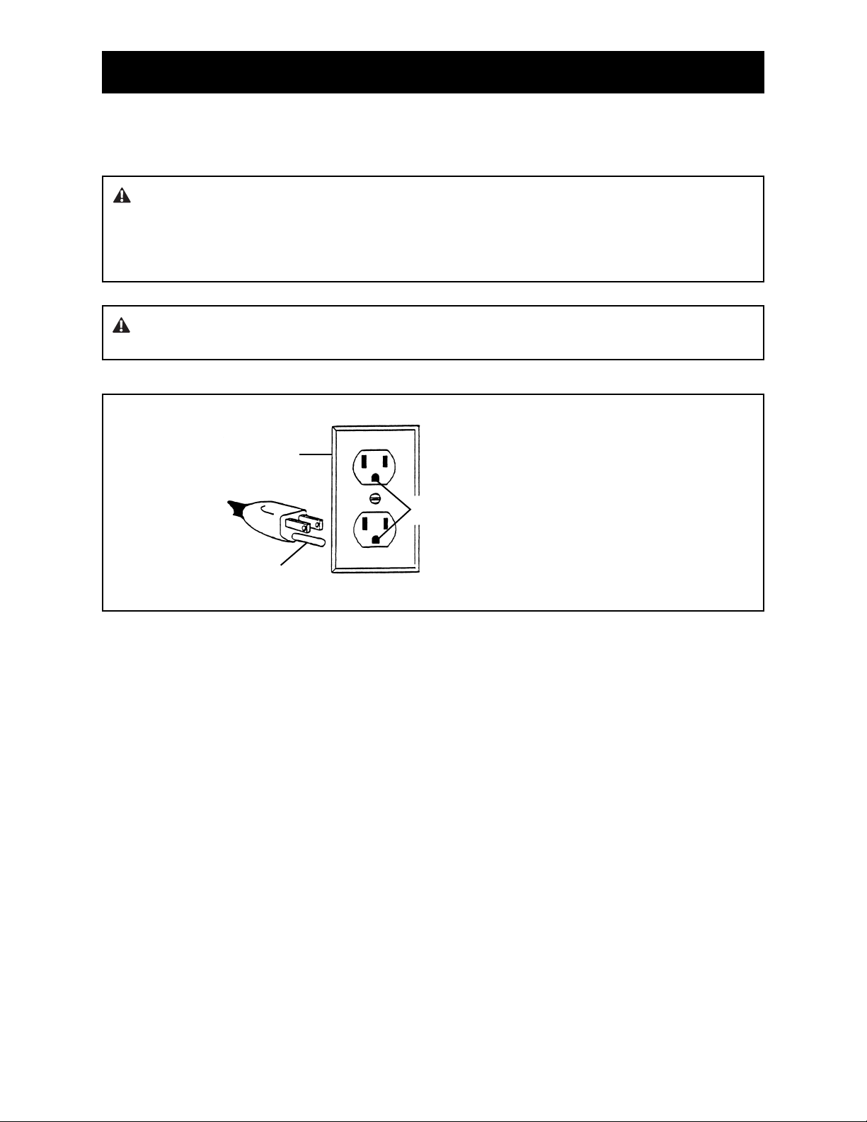
GROUNDED TOOLS: TOOLS WITH THREE PRONG PLUGS
Tools marked “Grounding Required” have a three wire cord and three prong grounding plug. The plug
must be connected to a properly grounded outlet (See Figure A). If the tool should electrically malfunction
or break down, grounding provides a low resistance path to carry electricity away from the user, reducing
the risk of electric shock.
The grounding prong in the plug is connected through the green wire inside the cord to the grounding
system in the tool. The green wire in the cord must be the only wire connected to the tool's grounding
system and must never be attached to an electrically “live” terminal.
Your tool must be plugged into an appropriate outlet, properly installed and grounded in accordance with
all codes and ordinances. The plug and outlet should look like those in Figure A.
Figure A
2
1
3
GROUNDING
1. Cover of grounded outlet box
2. Outlet ground
3. Grounding prong
WARNING: Electrical cords can be hazardous. Misuse can result in fire or death by electrical
shock. Read carefully and follow all directions.

Page 10
RULES FOR SAFE OPERATION
EXTENSION CORDS
Grounded tools require a three wire extension cord. As the distance from the supply outlet increases, you
must use a heavier gauge extension cord. Using extension cords with inadequately sized wire causes a
serious drop in voltage, resulting in loss of power and possible equipment damage or circuit breaker
failure.
The smaller the gauge number of the wire, the greater the capacity of the cord. For example, a 14 gauge
cord can carry a higher current than a 16 gauge cord. When using more than one extension cord to make
up the total length, be sure each cord contains at least the minimum wire size required. If you are using
one extension cord, add the nameplate amperes and use the sum to determine the required minimum
wire size.
GUIDELINES FOR USING EXTENSION CORDS
• Two twelve gauge extension cords are required to run the machine.
• If more than 100 feet is required for cord length (50 feet for each power cord and 50 feet for each
extension cord), for 110 volt we recommend the use of 10 gauge extension cords or heavier. Extension
cord specifications for EU; cord must have nominal cross-sectional area of 1.5 mm2 and be polyvinyl
chloride H05VV-F (227 IEC 53) or polychloroprene H05RN-F (245 IEC 57) or higher.
• If you are using an extension cord outdoors, make sure it is marked with the suffix “W-A” (“W” in
Canada) to indicate that it is acceptable for outdoor use.
• Be sure your extension cords are properly wired and in good electrical condition. Always replace a
damaged extension cord or have it repaired by a qualified person before using it.
• Protect your extension cords from sharp objects, excessive heat and damp or wet areas.
• Keep away from water. Do not use if wet.
• Inspect thoroughly before each use. DO NOT USE IF DAMAGED.
• Make sure equipment is OFF before connecting cord outlet.
• FULLY INSERT plug into outlet.
• Do not remove, bend or modify any metal prongs or pins of cord.
• Do not use excessive force to make connections.
• Do not connect a three prong plug to a two-hole cord.
• Avoid overheating. Uncoil cord and do not cover it with any material.
• Do not run machine over cords.
• Do not walk on cords.
• Do not drive or place objects over cord.
READ AND SAVE ALL INSTRUCTIONS FOR FUTURE REFERENCE.
WARNING: Electrical cords can be hazardous. Misuse can result in fire or death by electrical
shock. Read carefully and follow all directions.
WARNING: If cords are damaged they must be replaced by the manufacturer or its service
agent or a similarly qualified person in order to avoid a hazard.

Page 11
• Only qualified, trained personnel should operate this unit.
• Loose or damaged parts should be replaced immediately. Failure to do so could cause equipment
damage or serious injury.
• Switches, cord, plug and receptacle should be inspected. (Disconnect power before repairs to prevent
electrical shock). Unplug when not in use. Do not use if defective. Switches should return to off
when released.
• Be aware of the proximity of the power cord when machine is being operated.
• Power control box, motor and switches should be completely enclosed at all times with no
exposed wiring.
• Disconnect power from unit before servicing or changing blades. Failure to do so can cause
electrical shock.
• Only use National components. Failure to do so could cause damage or serious injury.
• Always be aware of support personnel and their proximity when in operation. Block off work area.
• Support personnel should never stand next to machine, in front of or behind machine while machine is
running. Failure to do so could cause serious bodily injury or death.
• Manual should be kept with machine in supplied holder for access by operator at all times.
• Always wear eye protection when running machine.
• Never defeat switches or guards.
• Remove blade when machine is not in use and/or lower cutting head to floor. Failure to do so could
cause serious bodily injury.
• Wear gloves when changing blades.
5110 SAFETY INSTRUCTIONS
WARNING: Know and understand before operation. Failure to do so could cause damage to
equipment or bodily injury.
Read and understand operators instruction manual and instructional video
before operating this equipment.
WARNING: Failure to follow any of the above instructions could cause damage to machine,
damage to property or serious bodily injury or death.
Page 12
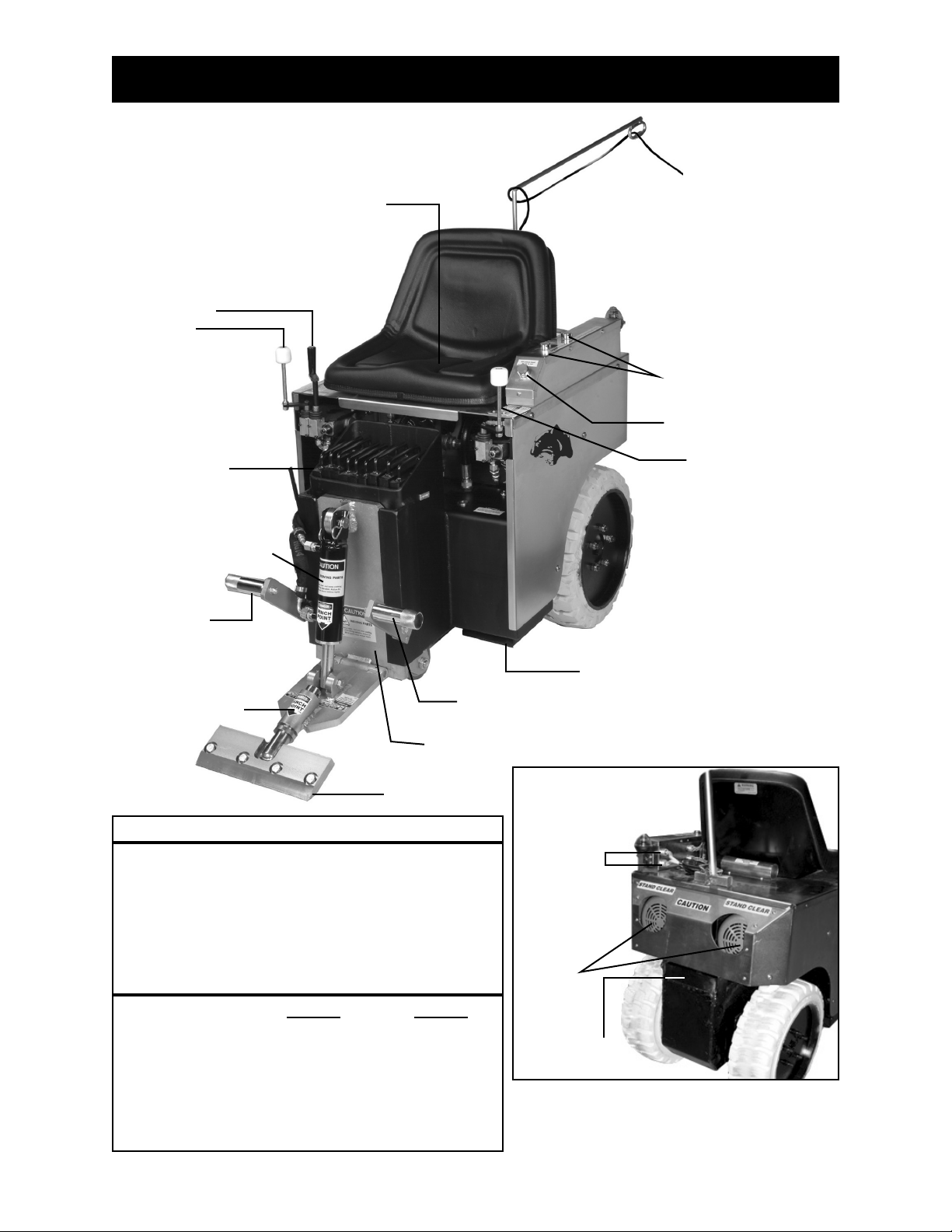
5110 FEATURES/SPECIFICATIONS
Rotating Extension
Cord Guide
Safety Shut Off Switch
(under seat)
Motor
Switches
Forward/Reverse
Neutral Break
Adjustable
Slide Plate
Power Off Switch
“Kill Switch”
Cutting Head
Cylinder Lift
Forward/Reverse
Neutral Break
Removable
Cutting Head
Foot Rest
Foot Rest
Fork Lift
Cup
Motor
Connections
Dual 115
Volt Motors
Cylinder
Front weight
compartment
Lower Cutting
Head Support
Rear Weight
Compartment
SPECIFICATIONS
Width: 24-1/2 inches
Height: 27 inches
Height w/Seat: 39-1/2
Length without Jaw: 50 inches
Empty Weight: 880 pounds
Weight (With Added Front weight): 1186 pounds
Speed: Up to 113 feet per minute
MOTOR INFORMATION
RPM
Hz
Volts
HP
Amps-Full Load
1725
60
115
1.5
13.5
1425
50/60
230
1.1 KW
6.5
Continuous Duty
115 Volt
230 Volt

Page 12.1
5110 FEATURES/SPECIFICATIONS
VIBRATION/SOUND DATA
VIBRATION DATA:
Axis
X
Y
Z
Vector
Sum
Stationary
>0.1
0.3
0.4
>0.1
Moving
0.5
0.3
0.1
0.6
Whole Body
Vibration Levels in m/s^2
Axis
X
Y
Z
Vector Sum
Left
0.5
0.3
0.6
0.9
Right
1.4
1.4
0.5
2.0
Hand/Arm
Vibration Levels in m/s^2
Stationary
Moving
dBA
77.0
73.0
Operator Sound Level
dBA ref. 20 Pa
SOUND DATA:

Page 13
5110 OPERATING CONTROLS
POWER BOX (FIGURE A)
Note: It is necessary to be seated before starting machine to keep machine running. The two green
switches are the starting switches. Press one green switch at a time. This will start the motors
individually. The red switch is the shut off switch, also referred to as the "kill switch". See cord hook up for
plugging in the motor cords.
HYDRAULIC LEVERS (FIGURE B)
The hydraulic levers steer the machine. They are feathered spool valves. For smooth even movement,
move levers slowly. Fast movement on control levers will result in jerky, uneven movement.
• Move levers slowly.
• Both levers forward move the machine forward.
• Both levers backward move the machine backward.
• The left lever forward and the right lever backward turn the machine quickly to the right.
• The left lever backward and the right lever forward turn the machine quickly to the left.
• Only the left lever forward , turns the machine slowly to the right.
• Only the left lever backwards , turns the machine slowly to the left.
Figure A
Motor Cord
Outlets
Starting
Switches
Shut Off
Switch
“Kill Switch”
Hydraulic
Lever
Hydraulic
Lever
Figure B

Page 14
5110 OPERATING CONTROLS
CYLINDER LIFT (FIGURE A)
The cylinder lift lever raises and lowers the cylinder and cutting head. After setting slide plate to proper
height, use the cylinder lift lever to set blade to proper cutting angle. Pull back on the cylinder lift lever
to raise the cutting head. Push the cylinder lift lever forward to lower the cutting head. Continuing to
push the cylinder lift lever forward and it will adjust the angle of the cutting head. This will also jack up the
machine (See Figure B). This will need to be done when doing maintenance on the machine (ie: wheel
changing, front caster maintenance etc).
Figure A
Cylinder Lift
Lever
Figure B
WARNING: Disarm machine by removing the cutting head or dropping the cutting head to the floor
when the machine is not in use.
Page 15
5110 OPERATING CONTROLS
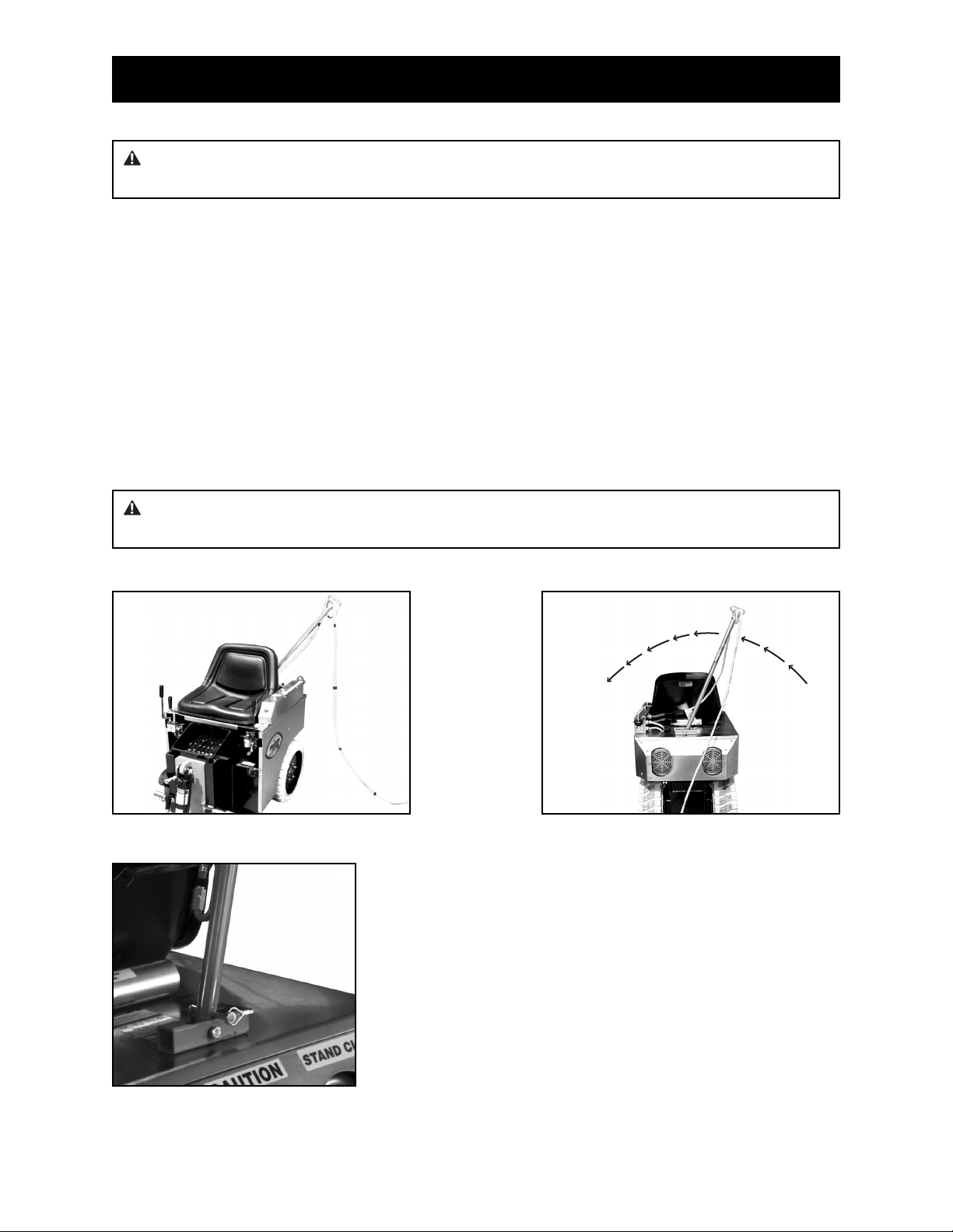
OPERATING AROUND THE CORD (FIGURE A)
The extension cord should be properly fed through the clip on the end of the flip arm cord guide. Loop
cord once. See the Cord Hook Up in the manual. The flip arm cord guide is designed to keep track of the
location of the electrical cord, especially when backing up and turning.
• Keep cord to side and slightly forward.
• Always work away from the cord.
• When backing up or making a sharp turn, check the location of the cord.
• Flip arm moves from side to side to help to keep electrical cords from being ran over (See Figure B).
• Adjust the flip arm cord guide in confined areas. Center position is achieved by moving cord guide arm
to the 12 o’clock position and securing in place with pin (See Figure C). This is used when going
through doorways or hallways. Hold cord straight out the back of the machine.
Figure C
WARNING: Disarm machine by removing the cutting head or dropping the cutting head to the floor
when the machine is not in use.
Figure A Figure B
CAUTION: Do not run over cord. Doing so could cause damage to equipment or severe
bodily injury.

Page 16
5110 OPERATIONAL TIPS
CASTER
Keep clean and free of debris, make sure it can move freely.
FOOT PEG
Keep feet resting and secured on foot pegs when operating machine.
SEAT SAFETY SWITCH
The seat safety switch is mounted under the center portion of the seat. This switch is designed as an
emergency shut off. If you are not sitting down on the seat, the machine will shut off. Warning: Do not
alter switches.
DISARM MACHINE
Remove blade or drop cutting head to the floor when machine is not in use.
DISCONNECT MACHINE FROM POWER
Never change cutting head or service blade while machine is running.
LEAKAGE
Keep fittings and hoses tight. If a leak is noticeable, retighten fitting. If leakage persists, remove the
connection and inspect.
POWER CORD
Be aware of where the power cord is. Do not run over the cord. If an electrical cord is damaged it must be
replaced by the manufacturer or its service agent or a similarly qualified person in order to avoid a
hazard.
ANGLE OF THE HEAD IS SET STEEP
When raising the front of the machine to a steep angle, the bottom of the slide plate should be raised so it
is higher or even with the bottom of the guide channels.
Page 17
HOW TO PLUG IN CORDS
SIZE & GAGE OF EXTENSION CORD
Grounded tools require a three wire extension cord. As the distance from the supply outlet increases, you
must use a heavier gauge extension cord. Using extension cords with inadequately sized wire causes a
serious drop in voltage, resulting in loss of power and possible equipment damage or circuit breaker failure.
The smaller the gauge number of the wire, the greater the capacity of the cord. For example, a 14 gauge
cord can carry a higher current than a 16 gauge cord. When using more than one extension cord to make
up the total length, be sure each cord contains at least the minimum wire size required. If you are using
one extension cord, add the nameplate amperes and use the sum to determine the required minimum
wire size.
• Two twelve gauge extension cords are required to run the machine.
• If more than 100 feet is required for cord length (50 feet for each power cord and 50 feet for each
extension cord), for 110 volt we recommend the use of 10 gauge extension cords or heavier. Extension
cord specifications for EU; cord must have nominal cross-sectional area of 1.5 mm2 and be polyvinyl
chloride H05VV-F (227 IEC 53) or polychloroprene H05RN-F (245 IEC 57) or higher.
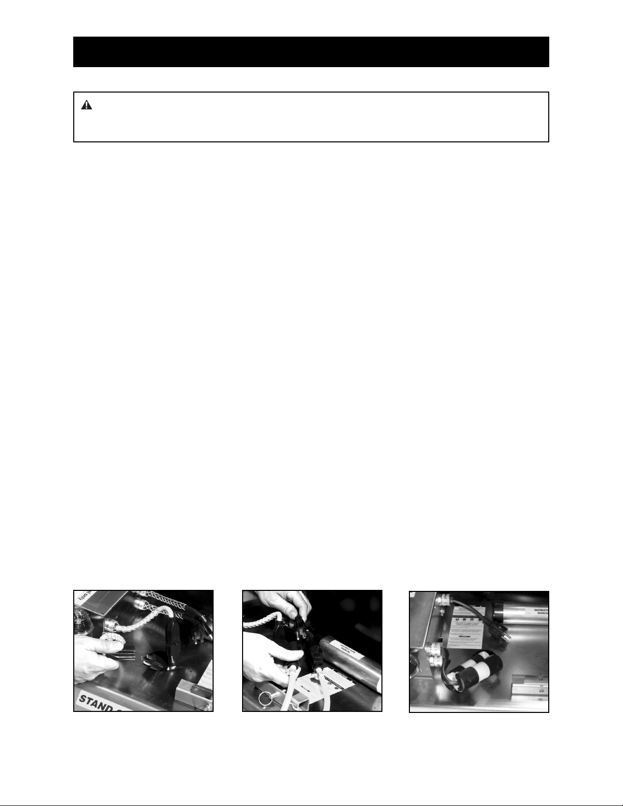
CORD HOOK-UP
Machine is supplied with a fifty-foot twin cord and two single fifty-foot 12 gauge extension cords.
1. Connect both male motor cord plugs (from the back of the machine) into the female plugs on the
back of the power control box (See Figure A). Each plug controls a motor and they can be plugged in
either order. Make sure cords are tightly plugged together.
2. From the female end of the twin cord, go in 3 feet and make a loop in the cord. Insert the loop into
the clip on the end of the flip-arm/cord guide. The loop in the cord secures the cord from slipping or
pulling out of the cord guide.
A. For 110 volt; connect both female plugs into the male plugs on the side of the power control box
(See Figure B). Also, see “Outlet Testing” before plugging cords into outlet. Make sure cords are
tightly plugged together.
B. For 230 Volt; connect female plug into the male plug on the side of the power control box (See
Figure C). Also, see “Outlet Testing” before plugging cords into outlet. Make sure cords are
tightly plugged together.
WARNING: Electrical cords can be hazardous. Misuse can result in fire and/or death by electrical
shock. Read carefully and follow all directions. Never defeat safety features or bypass the electrical
control box. Doing so could cause property damage and/or serious injury.
Figure A Figure B Figure C

Page 18
HOW TO PLUG IN CORDS
OUTLET TESTING
If cords are plugged into the same outlet, start one motor at a time. Never start both motors at the same
time. If you can’t run both motors from the same outlet, plug the twin cord into the supplied extension
cords and test in two separate circuits. Choose outlets as far apart as is practical. The idea is to find
outlets on different circuits.
CORD LENGTH
For 110 volt, if the twin cord plugged into the supplied fifty foot (12 gauge) extension cords is not enough
length, convert to 10 gauge cords. The longer the cord length that is needed, lowering the gauge of the
cords will help to lower the amperage loss due to the cord length. Extension cord specifications for EU;
cord must have nominal cross-sectional area of 1.5 mm2 and be polyvinyl chloride H05VV-F (227 IEC 53)
or polychloroprene H05RN-F (245 IEC 57) or higher.
CIRCUIT BREAKER TROUBLESHOOTING
Use a transformer when circuit breakers have low voltage (See optional #5110-500 Buck & Boost). The
Buck & Boost increases the line voltage at a receptacle. A job-site with bad power, the use of a Buck &
Boost may solve the problem. It also works great when extension cords exceed 100 feet in length.
Example: A receptacle registering 90 volts, the Buck & Boost will increase it to 118 volts.
WALL RECEPTACLE TESTING
Determine the supply line with a volt meter (See optional #5110-501 Voltage Meter). Plug voltage meter
into a wall outlet to determine the voltage at that receptacle. If the voltage is too low, plug twin cord into
two separate circuits. Choose outlets as far apart as is practical. The idea is to find outlets on different
circuits or convert to a transformer.
WARNING: Only use the Buck & Boost when the voltage has been determined at the wall
receptacle. Failure to do so could cause severe damage to equipment or possible injury.
WARNING: If the supply cord is damaged, it must be replaced by the manufacturer or its service
agent or a similarly qualified person in order to avoid a hazard.
Page 19
5110 LOADING/UNLOADING
• Always remove blade and cutting head when machine is being moved or transported
• Cutting head and slide plate can be removed to make the machine more compact.
• NEVER leave machine unattended on an incline.
• Removing added weights help to make the machine easier and safer to move in and out of a vehicle.
DOCK HEIGHTS
It is best to load or unload the machine from a level/equal dock height (a van from a van dock height, a
truck/semi from a regular dock height).
POWER-GATE
A power-gate can be used when the dock height is not available. Make certain the machine is secure so
it does not roll off the power-gate. To better secure machine, raise machine on to the lower cutting head
support raising machine off the caster.
RAMPS
To be safe, the ramp needs to be very long to accommodate the machine being loaded/unloaded.
Remove added weight. Make sure ramp is secured. Do not have at a steep incline. The use of a power
winch or hand come-a-long is much safer. For a van, the ramp should be 12 to 18 feet in length
depending on the depth of the incline. For truck height taller than a van, longer ramps will be needed.
See OSHA guidelines. It is not recommended to drive the machine, connected with power, on a ramp.
Make sure ramp is secure and has good contact before using. Failure to do so could cause ramp to fall
away from the vehicle.
Note: See correct and safe operating angels and center of gravity on page 20.1.
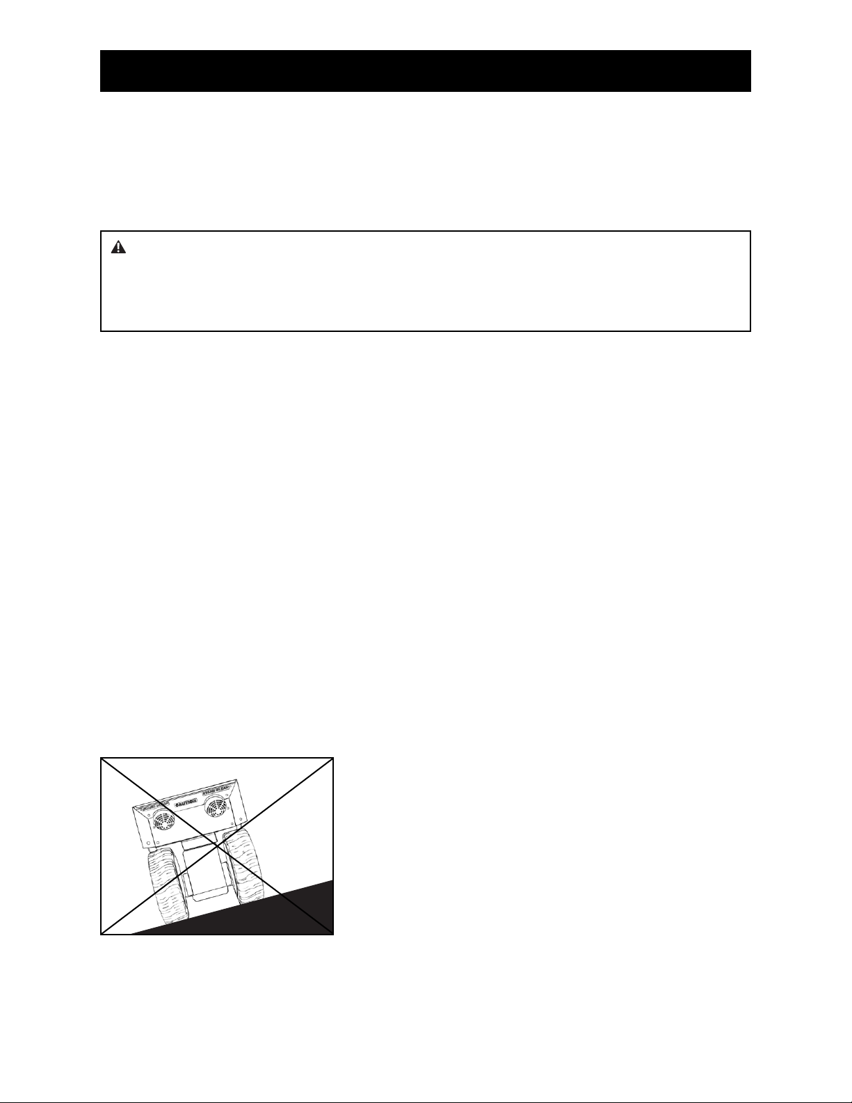
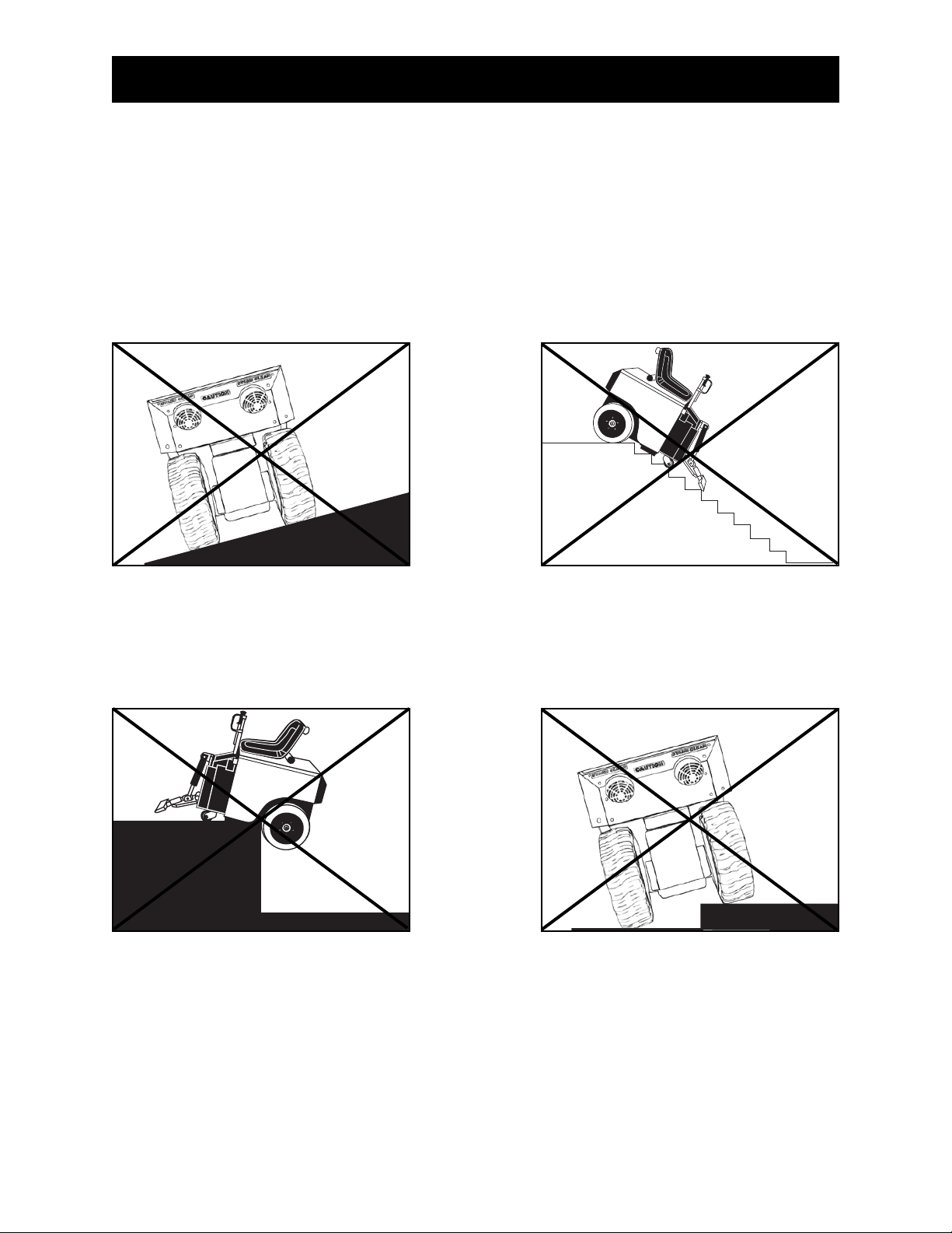
WARNING: Machine has a swivel front caster. Never side hill (See Figure A). The machine on a
incline without power, the front caster will cause machine to swing to the lowest point. If it is necessary
to run machine on an incline, run machine on cutting head. Place at least a 8'' cutting head in
machine. To keep from damaging floor, clamp a piece of carpet into cutting head to slide on the floor.
This will give positive contact with the floor when power is disengaged from the wheels.
Figure A
CAUTION: DO NOT “SIDEHILL”
Page 20
5110 LOADING/UNLOADING
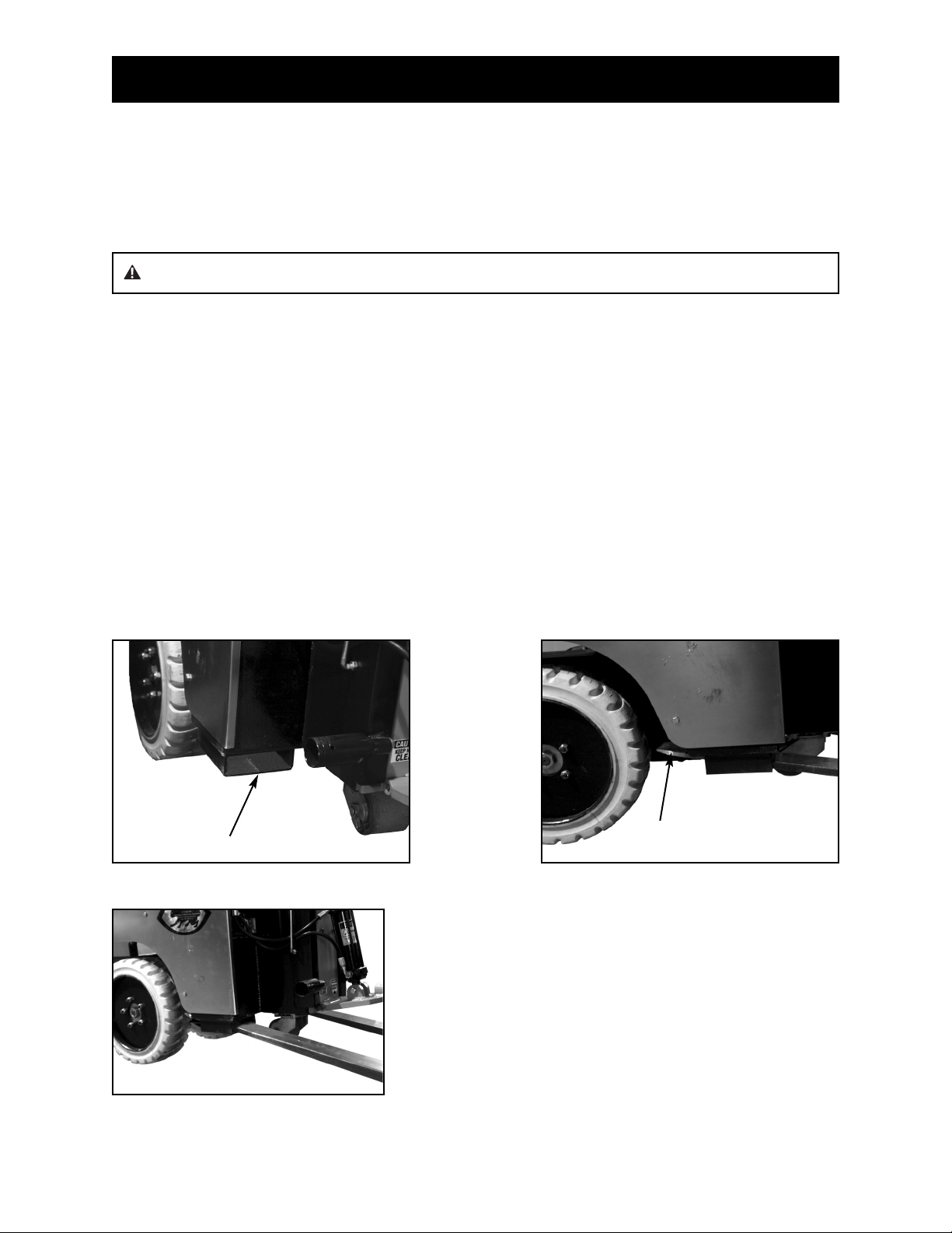
FORKLIFT CUPS
There are two forklift cups mounted under the front of the machine (See Figure A). Slide fork lift forks
through forklift cups. Slide forks all the way back to touch the rear tire (See Figure B). Before lifting
machine, secure machine to fork lift with heavy 3000 lb. or heavier rope or chain. Tilt forks back to lift
machine (See Figure C).
WINCHES
Winches should be used for safety when loading or unloading with ramps. 2000 lb. winch minimum.
TRANSPORTING
Secure machine down with ratchet straps when transporting the machine. To keep machine from rolling,
hydraulic levers should not be locked in the forward or backward position. Hydraulic levers should be
straight up in the "neutral" position. This helps to lock drive wheels. Lift machine off swivel caster onto
lower cutting head support for better stabilization. Proper securing straps need to be rated at least twice
the weight of the machine.
WHEEL CHOCKS
Wheel chocks will help to secure the machine but DO NOT use wheel chocks alone to secure the
machine.
Fork Lift Cup
Figure A
Forks on forklift should go
back to the rear wheel
Figure B
Figure C
WARNING: Never tilt machine forward. It could slide off fork lift forks.
Page 20.1
5110 CENTER OF GRAVITY
Be aware of your surroundings and machines operating angels. When changing from a low slide plate to
a high slide plate setting or a low cutting head angle to a high cutting head angle, the operating “attitude”
of the machine changes. When a floor surface is not level (ramps, inclines, large amounts of debris which
would lift the drive wheel of the machine, etc.), the center of gravity changes. Too much of an angle could
make the machine unsafe (a cause for tip-over). Do Not run the machine in unsafe environments.

Page 21
5110 JOB SITE MOVEMENT
• Always remove blade and cutting head when machine is being moved or transported
• Cutting head and slide plate can be removed to make the machine more compact.
• NEVER leave machine unattended on an incline.
• Removing added weights help to make the machine easier to move.
TAPING WHEELS
Taping the wheels with a wide like masking tape helps to prevent damage and dirt to floors during movein and move-out.
PALLETIZING
Only use a solid platform pallet. If a solid platform pallet is not available, place a piece of ¾" plywood on
top of a pallet. Using a forklift with the forks inserted in the forklift cups, place machine on pallet. Use
ratchet straps to secure machine to pallet.
FRONT WHEEL ASSEMBLY (FIGURE A)
The Front Wheel Assembly is an optional attachment (#5110-100) that is very helpful when moving the
machine around on a job-site or loading the machine that is not on a pallet. It allows machine stability and
safe transportation over any surface. It is easy and quick to attach or detach. Raise slide plate so the
bottom of the slide plate is higher or even with the bottom of the guide channels. Raise cylinder, insert
Front Wheel Assembly into cutting head. Secure with securing pin.
Figure A
WARNING: Protect others in work area. Provide barriers or shields as needed to protect
others from debris and machine operation. Operator should be aware of who is around them and
their proximity.
Caster
Plate
Note: Make sure the plate is parallel with the floor so the caster
swivels freely.
 Loading...