

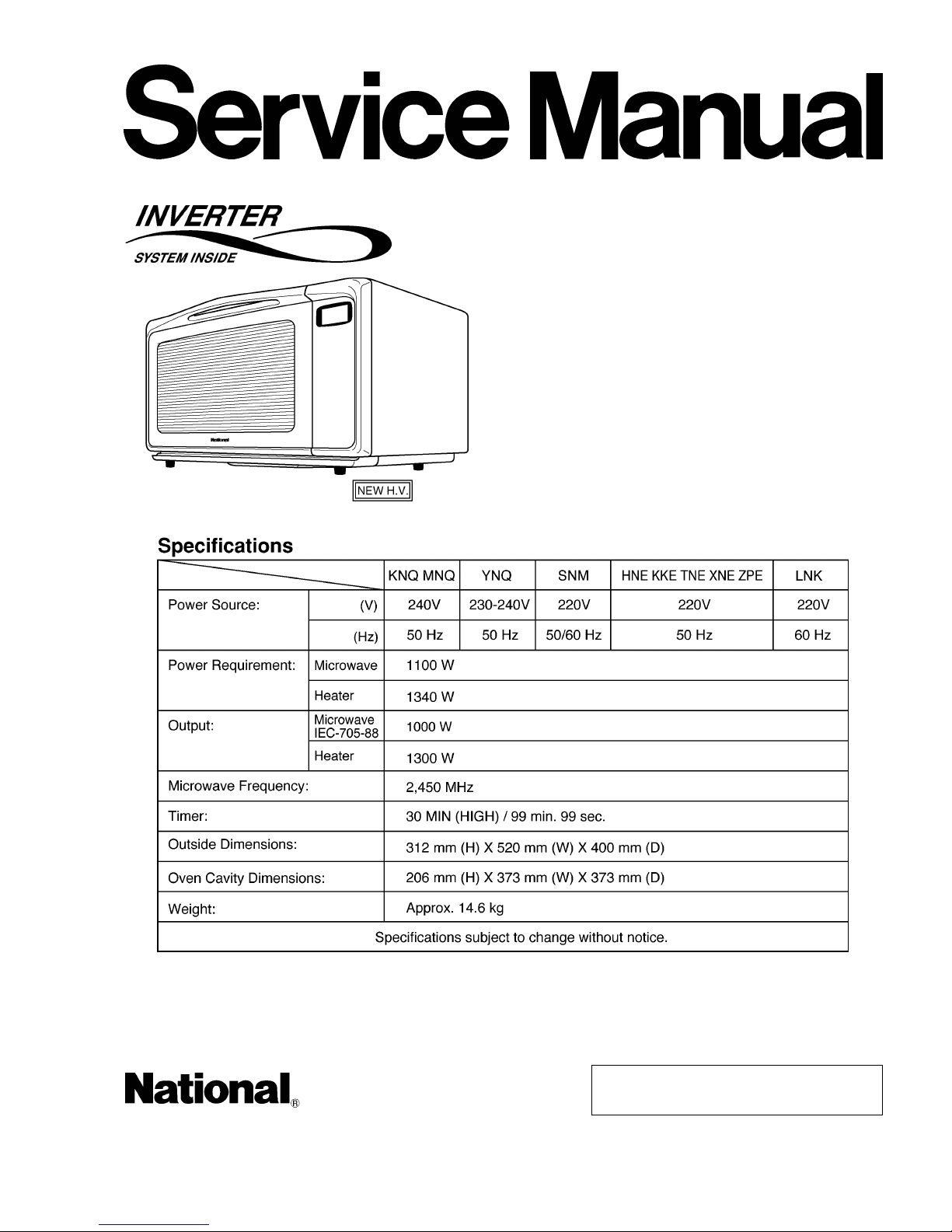
National NN-V690P, NN-V680W, NN-V690PS, NN-V680WS Service Manual
© 2001 Matsushita Electric Industrial Co., Ltd. All
rights reserved. Unauthorized copying and
distribution is a violation of law.
NN-V690P
NN-V690PS
NN-V680W
NN-V680WS
Microwave Oven
ORDER NO. MOD0101240C3
1 CONTROL PANEL 4
2 OPERATION AND DIGITAL PROGRAMMER CIRCUIT TEST
PROCEDURE
5
3 SCHEMATIC DIAGRAM
7
4 DESCRIPTION OF OPERATING SEQUENCE
9
5 CAUTIONS TO BE OBSERVED WHEN TROUBLESHOOTING
11
6 DISASSEMBLY AND PARTS REPLACEMENT PROCEDURE
13
7 COMPONENT TEST PROCEDURE
18
8 MEASUREMENTS AND ADJUSTMENTS
21
9 TROUBLESHOOTING GUIDE (NEW H.V.)
22
10 HOW TO CHECK THE SEMICONDUCTORS USING AN OHM
METER
27
11 INTRODUC ING OF TEST JIGS
28
12 EXPLODE D VIEW AND PARTS LIST
30
13 PARTS LIST
31
14 DOOR ASSEMBL Y
33
15 ESCUTCHEON BASE ASSEMBLY
34
16 PACKING AND ACCESOR IES
36
17 WIRING MATERIAL
38
18 DIGITAL PROGRAMMER CIRCUIT
39
19 DIGITAL PROGRAMMER CIRCUIT
41
CONTENTS
Page Page
2
NN-V690P / NN-V690PS / NN-V680W / NN-V680WS

20 INVERTER CIRCUIT 43 21 REF. NO. 35 INVERTER (U) 44
3
NN-V690P / NN-V690PS / NN-V680W / NN-V680
W
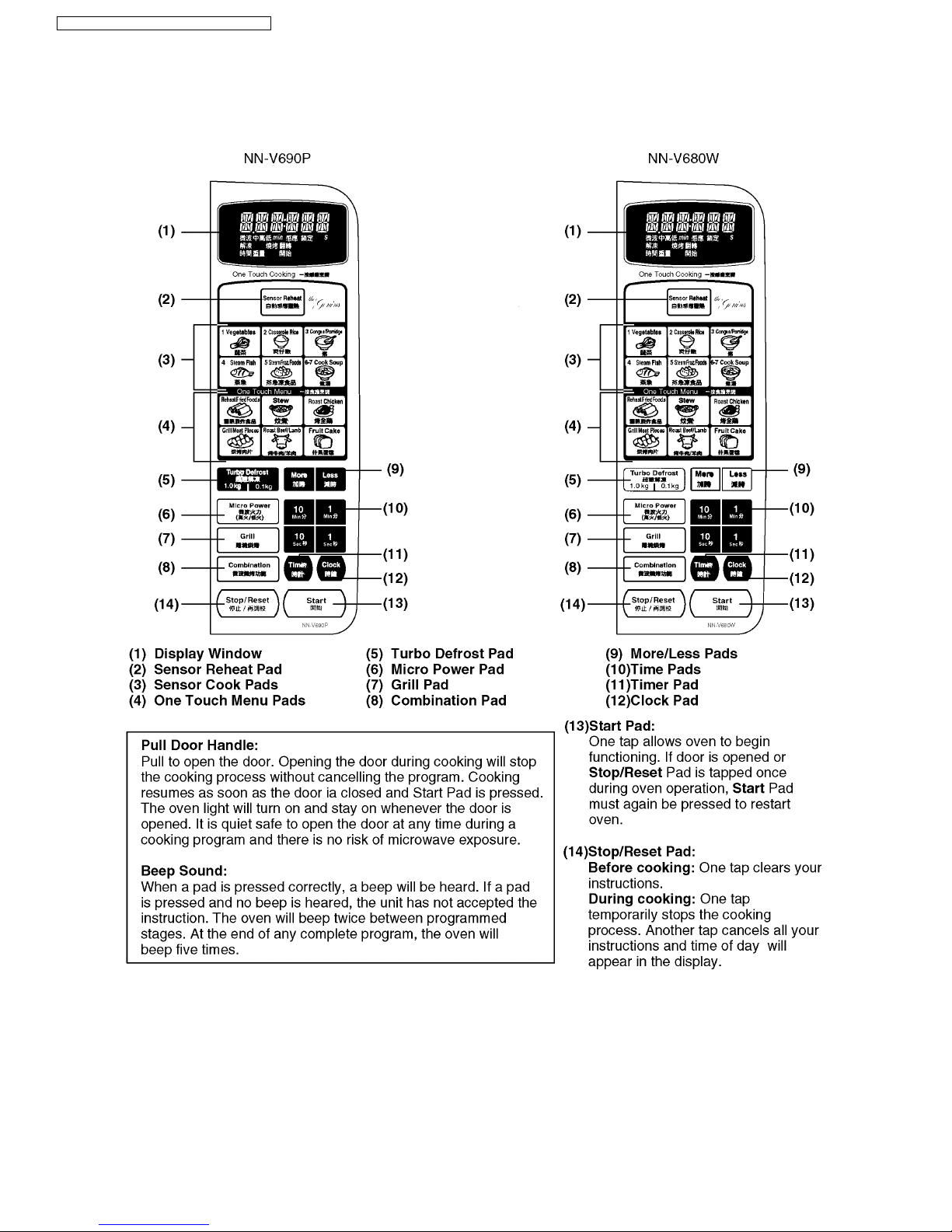
1 CONTROL PANEL
4
NN-V690P / NN-V690PS / NN-V680W / NN-V680WS
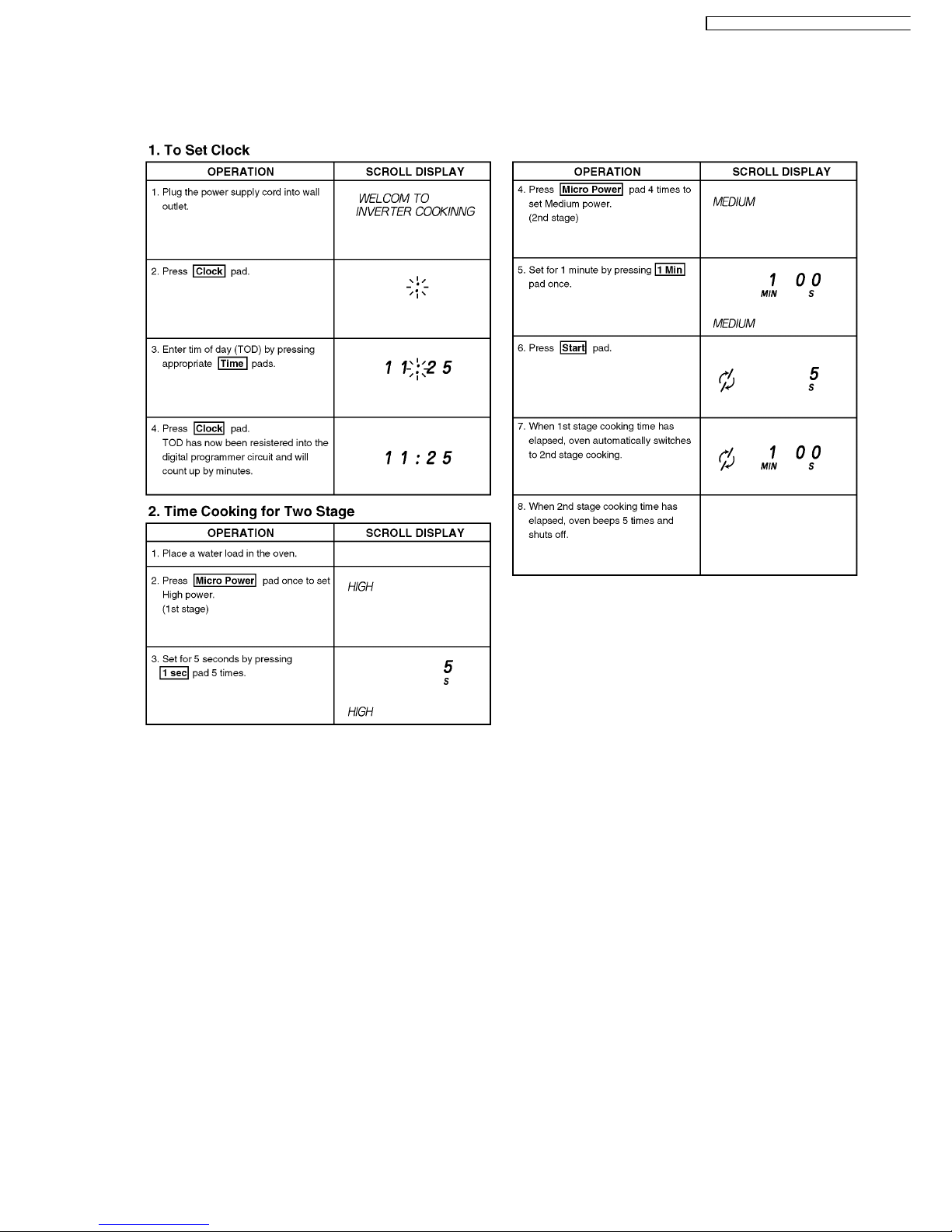
2 OPERATION AND DIGITAL PROGRAMMER CIRCUIT
TEST PROCEDURE
5
NN-V690P / NN-V690PS / NN-V680W / NN-V680
W
6
NN-V690P / NN-V690PS / NN-V680W / NN-V680WS
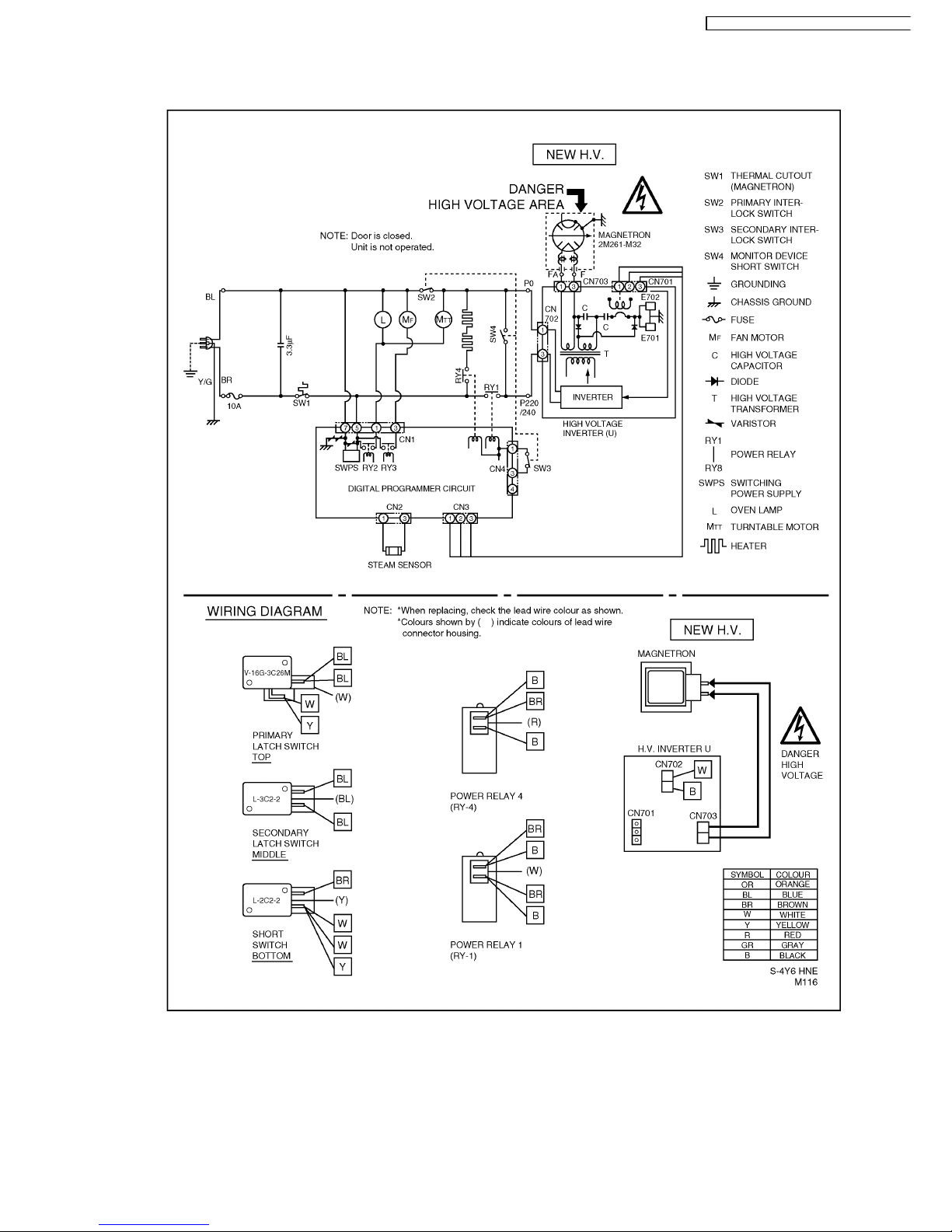
3 SCHEMATIC DIAGRAM
3.1. SCHEMATIC DIAGRAM (HNE, KNQ, KKE, LNK, MNQ, SNM, TNE, YNQ)
7
NN-V690P / NN-V690PS / NN-V680W / NN-V680
W
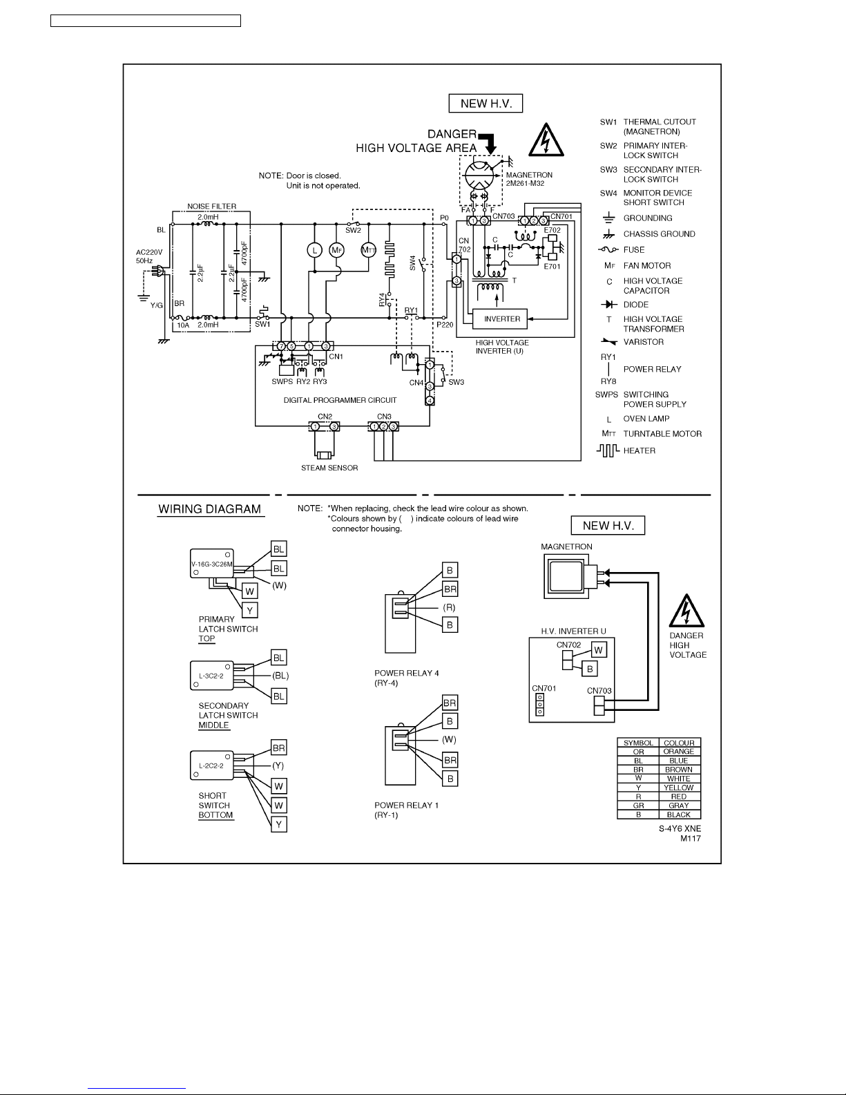
3.2. SCHEMATIC DIAGRAM (XNE, ZPE)
8
NN-V690P / NN-V690PS / NN-V680W / NN-V680WS
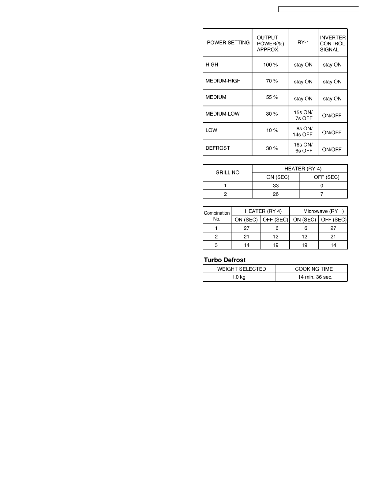
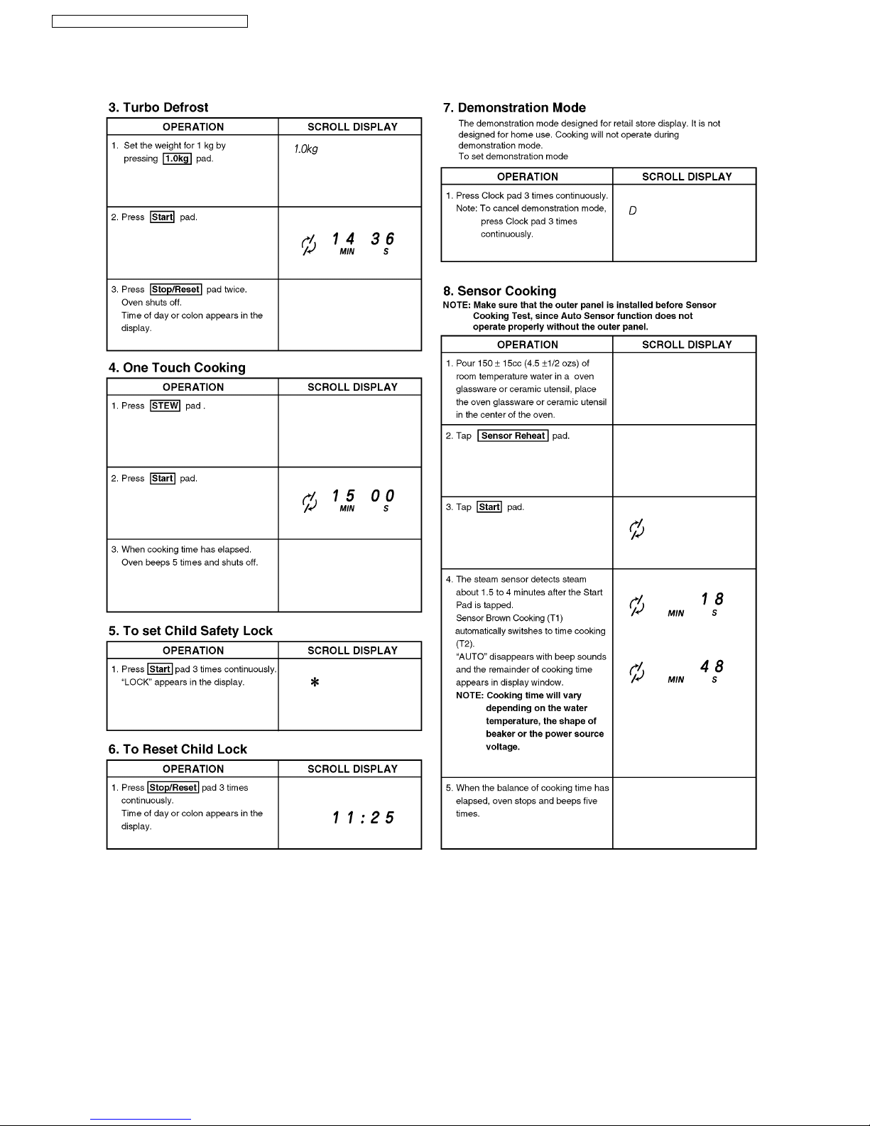
4.1. Variable power cooking
control
HIGH VOLTAGE INVERTER POWE R SUPPLY (U) controls
output power by the signal from Digital Programmer Circuit
(DPC). Power relay 1 stays on but the inverter drive signal to
control it's output power.
NOTE 1: The ON/OFF time ratio does not correspond with
the percentage of microwave power since approximately 2
seconds are required for heating of magnetron filament.
NOTE 2: If microwave cooking is over 3 minutes, fan motor
rotates for 1 minute after cooking to cool oven and electric
components.
4.2. Grill cooking
The digital programmer circuit generates the power relay 4
control signal at ON time during grill cooking.*
4.3. Combination cooking
Combination cooking is accomplished by microwave and grill
cooking. The digital programmer circuit controls ON-OFF time
of power relay 1 and 4 as shown in the table.*
*NOTE: After grill and combination cooking, fan motor
rotates for 7 minutes to cool oven and electric
components.
4.4. Auto Defrost Control
When those auto control feature is selected and Start pad is
pressed:
1. The digital programmer circuit determines the power level
and cooking time to complete cooking and indicates the
operating state in the display. The table shows the
corresponding cooking times for respective weight by
categories.
2. When cooking time in the display window has elapsed, the
oven turns off automatically by the controlled signal from
the digital programmer ciruit.
4 DESCRIPTION OF OPERATING SEQUENCE
9
NN-V690P / NN-V690PS / NN-V680W / NN-V680
W
4.5. One touch cooking (Auto
sensor cooking)
Auto sensor cooking is a revolutionary way to cook by
microwave without setting a power level or selecting a time.
All that is necessary is to select an Auto Sensor Program
before starting to cook.
Understanding Auto Sensor Cooking
As a food cooks, a certain amount of steam is produced. If the
food is covered, this steam builds up and eventually escapes
from the container. In Auto Sensor Cooking, a carefully
designed instrument, called the steam sensor element, senses
this escape of steam. Then, based upon the Auto Sensor
Program selected, the unit will automatically determine the
correct power level and the proper length of time it will take to
cook the food.
NOTE: Auto Sensor Cooking is successful with the foods
and recipes found in the Auto Sensor Cooking Guide.
Because of the vast differences in food composition, items
not mentioned in the Cooking Guide should be prepared in
the microwave oven using power select and time features.
Please consult Variable Power Microwave Cookbook for
procedures.
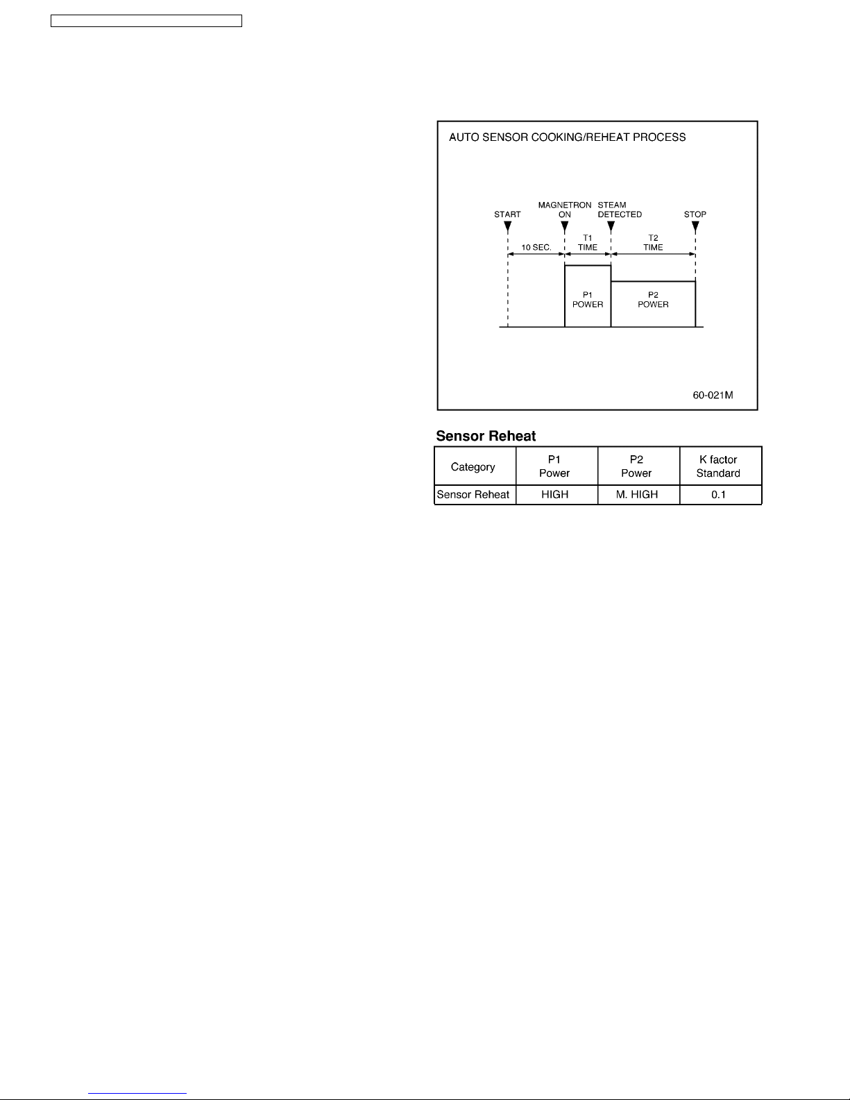
Explanation of the Auto Sensor Cooking process
1. During the first 10 second period there is no microwave
activity, and when calculating the T2 time by using the
formula below make sure this 10 seconds is subtracted
from the T1 time. In other words T1 time starts at the end of
the 10 second period.
2. T1 time The total amount of time it takes the microwave
oven to switch to T2 time after the 10 second period.
3. T2 time When the steam escapes from the cooking
container placed in the oven, the steam sensor detects it
and the microprocessor calculates the balance of cooking
time. This T2 time is then shown in the display and begins
counting down.
Balance of cooking time (T2 time)
The balance of cooking time which is called T2 time, can be
calculated by the following formula.
T2 time (in sec.) = T1 time X K factor
NOTE: Remember, the T1 time starts after the 10 second
period. The coefficient K is programmed Into the
microprocessor memory and they are listed in the
following tables along with the P1 and P2 powers.
NOTE: When "More" or "Less" pad is selected, the K factor
varies resulting in T2 time to be increased or decreased.
Example of calculating the T2 time
Example 1: If the T1 time is measured to be 2 minutes and 40
seconds after the 10 second period, and the Auto program
selected is Vegetables:
T2 = T1 X K
= 2 min. and 40 sec. X 0.1
= 160 sec. X 0.1
= 16 sec.
4.6. Auto Sensor Reheat
Auto Sensor Reheat is a quick and easy way to reheat
refrigerator and room temperature foods.
Simply press the reheat pad. There is no need to select power
level and cooking time.
NOTE: The Auto Sensor Reheat process is same as Auto
Sensor Cooking process.
10
NN-V690P / NN-V690PS / NN-V680W / NN-V680WS
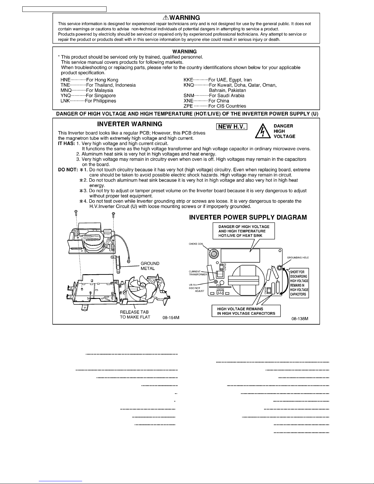
Unlike many other appliances, the microwave oven is highvoltage, high-current equipment. Though it is free from danger
in ordinary use, extreme care should be taken during repair.
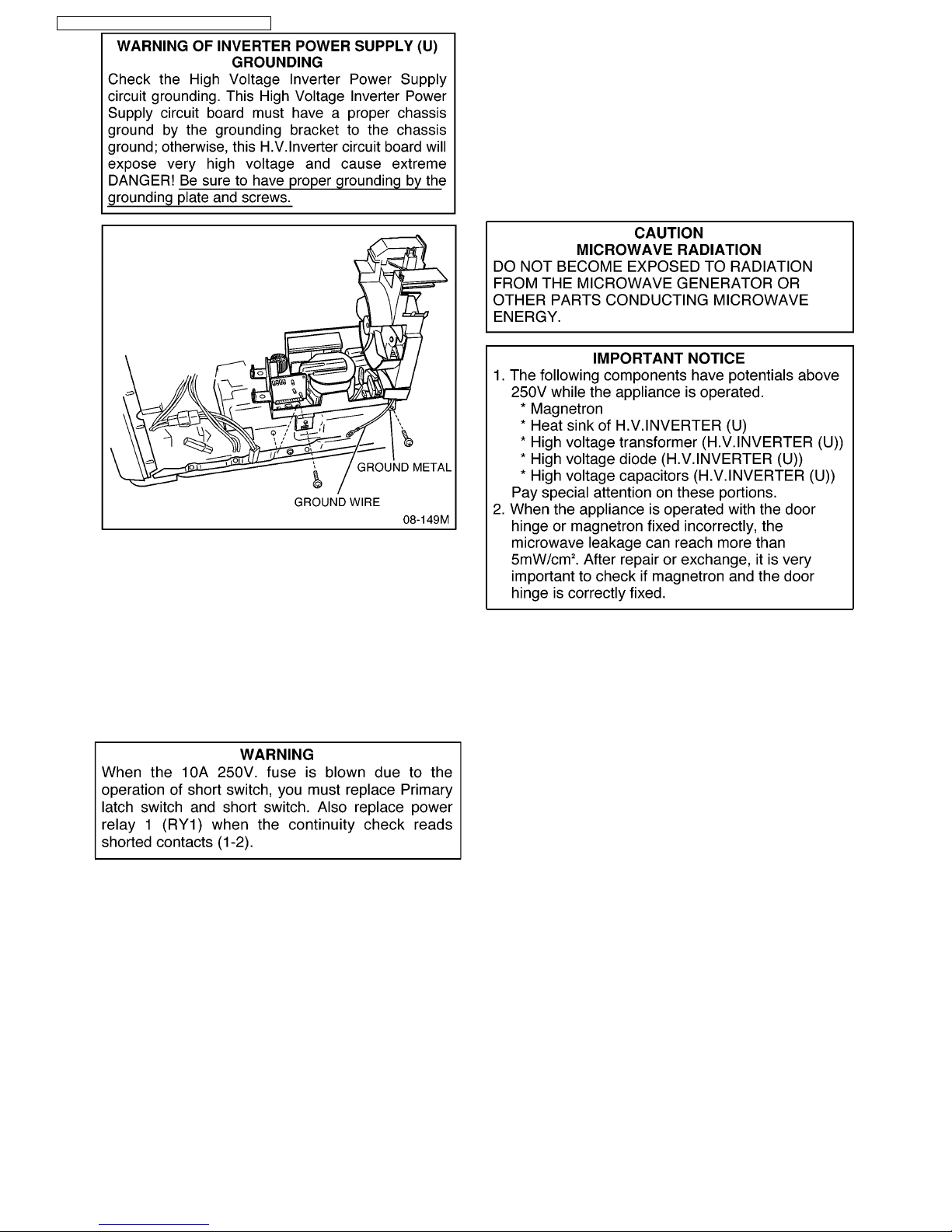
5.1. Check the grounding
Do not operate on a 2-wire extension cord. The microwave
oven is designed to be used when grounded. It is imperative,
therefore, to make sure it is grounded properly before
beginning repair work.
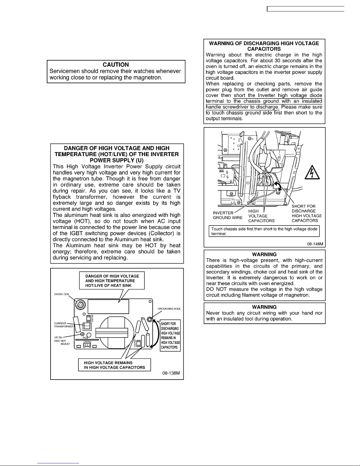
5.2. Inverter Warnings (NEW H.V.)
5 CAUTIONS TO BE OBSERVED WHEN
TROUBLESHOOTING
11
NN-V690P / NN-V690PS / NN-V680W / NN-V680
W
5.3. When parts must be replaced,
remove the power plug from
the outlet.
5.4. When the 10A 250V fuse is
blown due to the operation of
short switch:
1. This is mandatory. Refer to "Adjustments and
Measurement" for these switches.
2. When replacing the fuse, confirm that it has the appropriate
rating for these models.
3. When replacing faulty switches, be sure mounting tabs are
not bent, broken or otherwise deficient in their ability to hold
the switches.
5.5. Avoid inserting nails, wire, etc.
through any holes in the unit
during operation.
Never insert a wire, nail or any other metal object through the
lamp holes on the cavity or any other holes gaps, because such
objects may work as an antenna and cause microwave
leakage.
5.6. Confirm after repair
1. After repair or replacement of parts, make sure that the
screws of the oven, etc. are neither loose nor missing.
Microwaves might leak if screws are not properly tightened.
2. Make sure that all electrical connections are tight before
inserting the plug into the wall outlet.
12
NN-V690P / NN-V690PS / NN-V680W / NN-V680WS
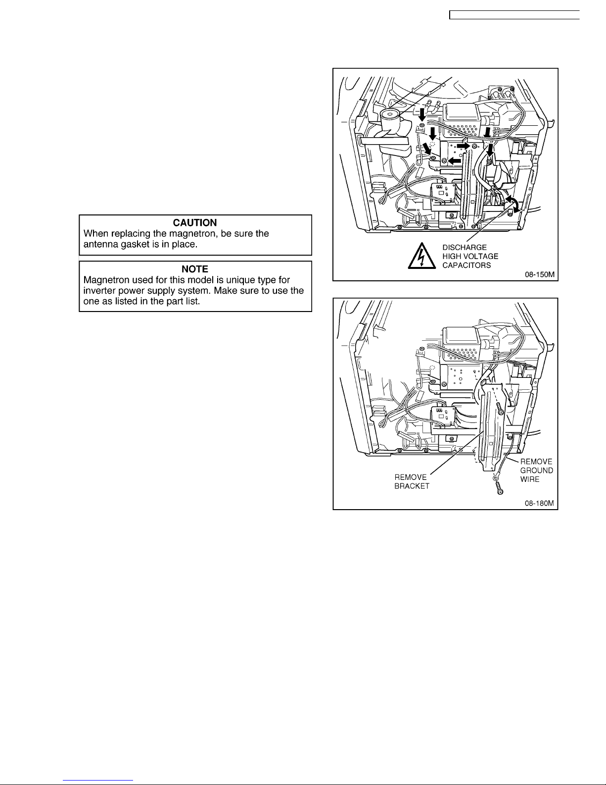
6.1. Magnetron
1. Discharge high voltage capacitors.
2. Remove A screw holding magnetron on bracket.
3. Remove 2 high voltage lead wires.
4. Remove circulation fan motor bracket and belt. (2 screws)
5. Remove air guide. (2 screws)
6. Remove 4 screws holding magnetron.
NOTE: After replacement of the magnetron, tighten
mounting screws properly making sure there is no gap
between the waveguide and the magnetron to prevent
microwave leakage.
NOTE: Magnetron used for this modes is unique type for
inverter power supply system. Make sure to use the one as
listed in the part list.
6.2. High Voltage Inverter Power
Supply (U) (NEW H.V.)
1. Discharge high voltage capacitors.
2. Remove 2 screws holding magnetron bracket. (Remove
grounding wire)
3. Remove 3 screws holding inverter and fan motor assembly.
4. Unplug 3 connectors of inverter PCB.
5. Remove 2 screws holding inverter PCB on to bracket.
NOTE: Do not pull by lead wires but make sure to pull
housing unless PCB or lead wire may break.
6 DISASSEMBLY AND PARTS REPLACEMENT
PROCEDURE
13
NN-V690P / NN-V690PS / NN-V680W / NN-V680
W

6.3. Digital programmer circuit
(DPC) and membrane key
board.
NOTE: Be sure to ground any static electric charge built up
on your body, before handling the DPC.
1. Disconnect all connectors from D.P.C.
2. Remove 2 screws holding escutcheon base and slide the
escutcheon base upward slightly with door closed.
3. Release CN5 connector's lock of DPC by pushing both
levers to inside and pull them upward, and remove flat
cable of membrane key board.
4. Remove 3 screws holding DPC.
To replace membrane key board
5. Remove escutcheon bracket from escutcheon base by
freeing 5 catch hooks on the escutcheon base.
6. On some models, the key board is not replaced with
individual parts. Instead, the entire escutcheon base
assembly must be replaced. Refer to parts list.
14
NN-V690P / NN-V690PS / NN-V680W / NN-V680WS
 Loading...