

Page 1
Revision A
April 14, 2006
LM95235 Evaluation Board User’s Guide
LM95235 Evaluation Board User’s Guide
© Copyright 2006 National Semiconductor Corporation 1 www.national.com
Page 2

LM95235 Evaluation Board User’s Guide
Table of Contents
Table of Contents 2
References 3
1.0 Introduction 4
2.0 Quick Start 5
3.0 Functional Description 7
4.0 Software Installation and Operation 8
5.0 Electrical and Mechanical Specifications 9
5.1 Electrical Specifications 9
5.2 Electrical Schematic 9
5.3 Evaluation Board Layout 10
5.4 Bill of Materials 11
5.5 Mechanical Specifications 11
© Copyright 2006 National Semiconductor Corporation 2 www.national.com
Page 3

LM95235 Evaluation Board User’s Guide
References
1. “LM95235 Precision Remote Diode Temperature Sensor With SMBus Interface and
TruTherm™ Technology” datasheet.
The latest copy of the LM95235 datasheet can be obtained by going to the National
Semiconductor website
www.national.com, by searching on “LM95235”, and then downloading
the LM95235.pdf file.
2. SensorEval Version 1.1.0a or later, Evaluation Board CD containing:
a. The SensorEval.exe executable program used to run the LM95235 Evaluation
Board.
b. A softcopy of this User’s Guide
c. A readme.txt file with useful information about the program.
d. A softcopy of the SensorEval Software manual.
© Copyright 2006 National Semiconductor Corporation 3 www.national.com
Page 4
1.0 Introduction
The LM95235 Evaluation Board is used together
with the National Semiconductor SensorEval
software (provided in the kit), and with a USB cable
(not provided in the kit), and with an external
personal computer (PC). Power to the LM95235
Evaluation Board is provided by the +5 VDC line of
the USB connection. No external power supply or
signal sources are required for operation of the
LM95235 evaluation board.
Before connecting the PC to the LM95235
evaluation board through the USB cable, the PC is
first turned on and allowed to go through its boot-up
procedure. The user installs and initiates the
SensorEval software. See Section 4.0 for details.
After the SensorEval software is running, the user
can connect the USB cable first to the computer and
then to the LM95235 Evaluation Board.
The PC should be able to recognize the board and
the user simply selects the LM95235 Eval Board
radio button.
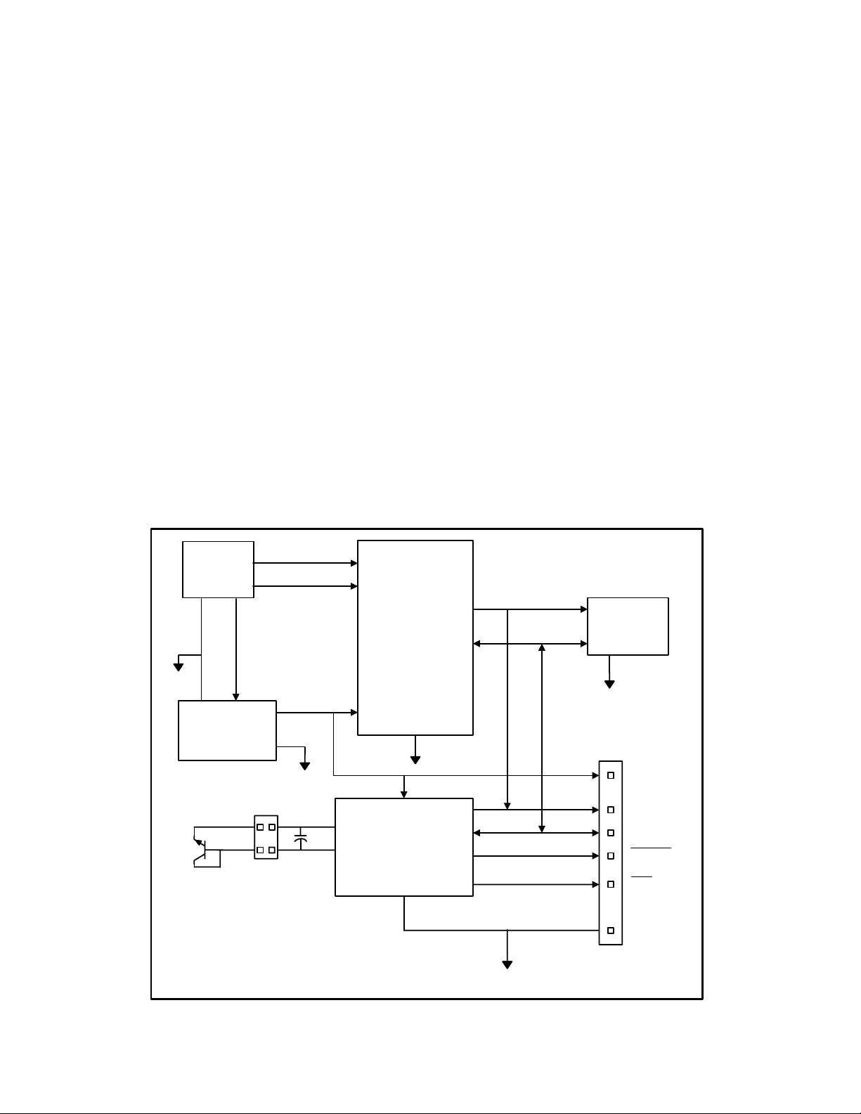
The block diagram below describes the LM95235
Evaluation Board itself. The USB input provides the
+5.0 VDC power to the board, which is regulated
down to 3.3 VDC to power the IC’s. The EEPROM
is programmed at the factory with a unique ID code
for this particular board. When the USB cable is
plugged in, the PC interrogates the USB devices and
can identify this device as the LM95235 Evaluation
Board.
The microcontroller on the board provides the serial
SMBus clock (SMBCLK), provides the SMBus data
(SMBDAT) signal, and relays the information from
the LM95235 to the PC via the USB lines.
The block in the lower right of the Block Diagram
shows the signals that are available to probe by the
user for the LM95235 device on the board.
1.1 Block Diagram
USB
Input
GND
Voltage
Regulator
Circuit
+5.0 VDC
+3.3 VDC
USB D+
USB D-
Microcontroller
Circuitry
U2
LM95235
SMBCLK
SMBDAT
EEPROM
Circuit
GND
VDD
SMBCLK
SMBDAT
T_Crit
OS/A0
GND
© Copyright 2006 National Semiconductor Corporation 4 www.national.com
GND
Page 5
2.0 Quick Start
1. Install the CD into the CD drive of the computer
and install the SensorEval software (see Section
4.0).
2. Hookup the USB cable between the PC or
notebook computer and the LM95235EVAL
board as shown in Quick Start Diagram (See
Section 2.1).
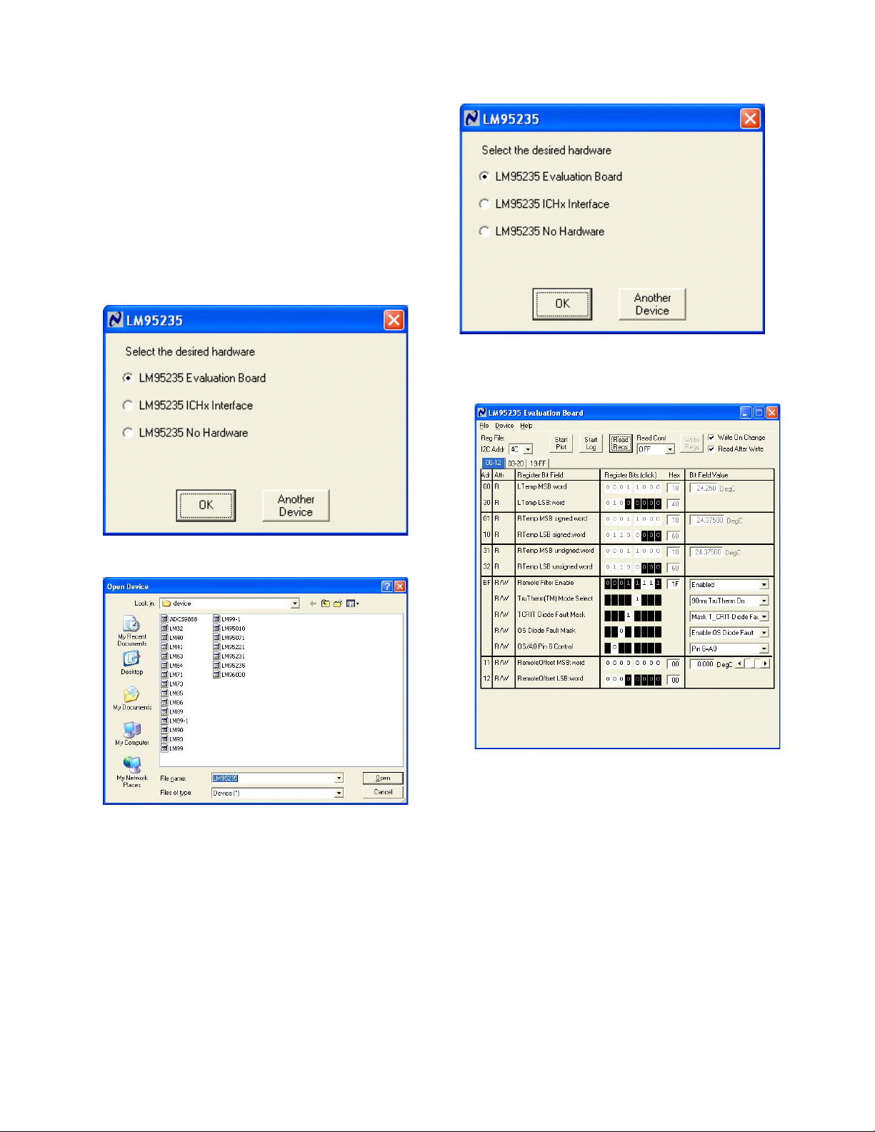
3. Run the SensorEval software clicking the icon
on the desktop. The first screen after the
installation will look like this:
Select the LM95235 Evaluation Board.
Click OK.
5. The next screen will look like this:
If not, select “Another Device”. The next screen
should look like this:
Make sure that “4C” is selected in the upper left
Select LM95235 and click on Open button.
4. The next screen (first screen after the first run of
the program) will look like this:
© Copyright 2006 National Semiconductor Corporation 5 www.national.com
box labeled “I2C Addr”. Select “All Regs” in the
“Read Cont” box to read all of the registers,
including the temperature registers continuously.
Page 6

6. The Screen should look like this:
Local (on-chip) and remote temperatures should read
continuously. The user can experiment with the
different settings of Address BF.
7. If the user clicks the 06-FF tab the next screen
will look like this:
.
The user can also select the 3904 diode or the
processor thermal diode called “90 nm”.
The user can experiment with the Mask settings. Also the
user can change the conversion rate. The next screen
shows the possibilities for the Conversion Rate.
© Copyright 2006 National Semiconductor Corporation 6 www.national.com
Page 7

8. If the user clicks on the Start Plot button a graph
box will appear and will graph the temperature. An
example is shown below
9. If the user selects the Start Log button the following
screen will appear. The user then enters the filename that
he chooses to log the data into.
© Copyright 2006 National Semiconductor Corporation 7 www.national.com
Page 8

2.1 Quick Start Diagram
Important! NO EXTERNAL POWER SUPPLY OR SIGNAL INPUTS ARE RE QUIRED!
Computer
with
SensorEval
software
loaded
USB Cable to
Computer
National Semiconductor
LM95235 Evaluation Board Rev. 1
LM95235
N/C
TCRIT#
N/C
OS/A0
SCL
SDA
+3.3
JP2
© Copyright 2006 National Semiconductor Corporation 8 www.national.com
Page 9

3.0 Functional Description
The LM95235 Evaluation Board, along with the
SensorEval Software, provides the system designer
with a convenient way to learn about the operation of
the LM95235 Temperature Sensor chip. The user
simply has to install the SensorEval software on his
PC, run it, connect the USB cable from the PC to the
Evaluation Board, and the user can read the
temperatures. It’s that simple! The user doesn’t have
to provide any power or external signals to the
evaluation board.
3.1 LM95235 Evaluation Board Connection Table
Connector Label Pin
Number
J1 N/A
1
USB Cable Input. Connect the USB cable to this jack after
the SensorEval software has been loaded on the PC.
V
. The +3.3 VDC voltage supplied by the on-board
DD
voltage regulator to the LM95235 V
connect an external power supply to this pin!
Power to the LM95235 Evaluation Board is taken
from the USB 5-Volt line. This +5 VDC is the input
to the on-board LM2950 low dropout voltage
regulator, which regulates the output voltage to +3.3
VDC. This output voltage powers the LM95235, the
on-board microcontroller, and the EEPROM chip
where the board ID information is stored.
The microcontroller provides the SMBus Clock
(SMBCLK) signal and the SMBus Data (SMBDAT)
signal to the LM95235 chip. This communication
between the LM95235 and the PC USB data lines is
controlled by the microcontroller. For all of the
details of this communication protocol see the latest
LM95235 datasheet, available at www.national.com.
Description
input pin. Do not
DD
Output header provides
user with signals for test
purposes only.
Do not apply any
external power or
signals to any of the
pins on these headers!
Connection to
temperature diodes
Do not apply any
external power or
signals to any of the
pins on these headers!
JP2
J4
2 SMBDAT. Data signal for the SMBus.
3 SMBCLK. Clock signal for SMBus.
OS#/A0. When this pin is pulled low it enables the
4
5 No Connection.
6
7 No Connection.
3, 4 Connect for D+ connection
1, 2 Connect for D- connection
Overtemperature Shutdown (OS) feature. When this pin is
pulled high it is the Address pin function.
T_Crit#. This is the signal that goes low when the Set
Temperature is exceeded.
© Copyright 2006 National Semiconductor Corporation 9 www.national.com
Page 10

4.0 Software Installation and Operation
4.1 Installation
The CD provided in the LM95235 Evaluation Board Kit
contains the SensorEval software used to make the LM95235
Evaluation Board operate with the user’s PC. It is assumed
that the user will be using a PC with a Pentium® III or higher
processor and Microsoft Windows® XP/2000/98/ME
operating system.
The software is installed as follows:
1. Insert the SensorEval CD into the CD drive of the
PC. See details in the readme.txt file.
2. The software manual, provided on the CD, may be
useful to the user during this process.
3. Follow all of the Installation instructions in the
windows as the SensorEval software is installing.
4. The installation process will put an icon on the PC
desktop so that the SensorEval program will run
when the icon is double-clicked.
4.2 Operation
Follow the following procedure for operation the LM95235
Evaluation Board using the SensorEval software:
1. Run the SensorEval program by either double-
clicking on the icon on the desktop or by selecting
Start, Program Files, National Semiconductor,
SensorEval.
2. Plug in the USB cable on both the PC and the
LM95235 Evaluation Board.
Follow the register setup steps given in section 2.0 Quick Start
of this User’s Guide. Make sure that you are following the
given procedure for the specific evaluation board you are
working with.
Refer to the electrical schematic, layout and connector
diagrams for proper connections to external remote thermal
diodes.
© Copyright 2006 National Semiconductor Corporation 10 www.national.com
Page 11

7
5
.0 Electrical and Mechanical Specifications
5.1 Electrical Specifications
Power Requirements
The Board uses the +5.0 VDC and GND lines from the USB connection.
This +5.0 VDC voltage is regulated down to +3.3 VDC for board power.
* NO EXTERNAL POWER SUPPLY INPUTS ARE REQUIRED *
5.2 Electrical Schematic
+ 3.3 VDC
Use a 0.1 uF capacitor for each
Vcc pin of U2 and Reserved_6 pin.
L1
1 uH
J3
USB-B
VBUS
D-
D+
GND
SHELL_1
SHELL_2
U4
AT24C02-10SI-2.7
1
A0
2
A1
3
A2
4
Vss
C14
2.2uF
1
2
3
4
5
6
R12
1M
Vcc
WP
SCL
SDA
U1
LP2950CDT-3.3/TO252
IN1OUT
GND
C15
0.1uF
8
7
6
5
3
C16
2.2uF
R7 22
R9 22
R11 1.5K
+ 3.3 VDC
R13
1.5K
0.1uF
1.5K
C1
0.1uFC20.1uFC30.1uFC40.1uFC50.1uF
+ 3.3 VDC
C9
27
40
29
20
Vcc3
Vcc4
PB0/T2
RESERVED_619RESERVED_7
CY7C64603-52NC
WAKEUP#
Gnd221AGnd
Gnd113Gnd3
4
8
26
33pF
32
31
33
34
30
PB4/INT4
PB1/T2EX
PB3/TXD1
PB2/RXD1
PB5/INT5#
U2
Gnd439Gnd547Gnd6
RDY2/AOE
XCLK38RESERVED_422RESERVED_5
9
16
52
42
R3
100k
C17
1
14
C18
0.1uF
C20
R14
0.1uF
5
Vcc1
Vcc2
AVcc
28
RESET#
24
USBD-
25
USBD+
18
DISCON#
10
PA4/FWR#
11
PA5/FRD#
12
CLKOUT
SCL
2
SCL
SDA
3
SDA
Y1
12 MHz
R4
1M
6
XIN
PB6/INT6
PB7/T2OUT
CTL2/AOUTFLAG
CTL0/AINFLAG
PC0/RxD0
PC1/TxD0
PC2/INT0#
PC3/INT1#
PC6/WR#
PC7/RD#
RESERVED_3
RESERVED_215XCLKSEL
RESERVED_1
17
23
PC4/T0
PC5/T1
0.1uF
7
C6
C10
33pF
MMBT3904/SOT
XOUT
35
36
37
41
43
44
TCRIT
45
OS/A0
46
48
49
50
51
+5.0 ± 0.1 V,
100 mA max.
C11
2.2uF
Q1
J4
HEADER 2x2
Shunt to select the PCB
temperature diode.
+ 3.3 VDC
R1
0
C12
C13
0.1uF
100 pF
LM95235
U3
1
VDD
C19
100 pF
2
D+
3
D-
4
TCRIT#
34
12
SMBCLK
SMBDAT
OS/A0
8
7
OS/A0
6
5
GND
R2
R15
1.5K
1.5K
SCL
SDA SDA
OS/A0
TCRIT
+3.3 VDC
SCL
TP1
GND
TP2
GND
TP3
GND
JP2
1
3
2
4
5
6
7
HEADER 1X
TP4
GND
SCL
SDA
Schematic of the LM95235 Evaluation Board
© Copyright 2006 National Semiconductor Corporation 11 www.national.com
Page 12

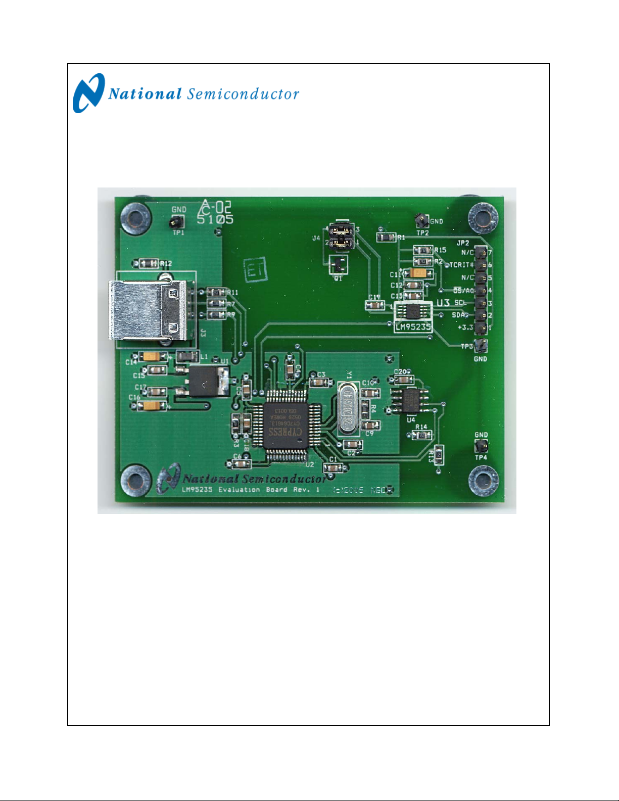
5.3 Evaluation Board Layout
Figure 5.3 Layout diagram of the LM95235 Evaluation Board
(Note: socket and socket area not stuffed.)
© Copyright 2006 National Semiconductor Corporation 12 www.national.com
Page 13

5.4 Bill of Materials for LM95235 Evaluation Board
Item Qty Reference Part PCB Footprint
1 11 C1,C2,C3,C4,C5,C6, Capacitor, SMD, ceramic, 0.1uF sm/c_0805
C12,C15,C17,C20
2 2 C9, C10 Capacitor, SMD, ceramic, 33 pF sm/c_0805
3 3 C11,C14,C16 Capacitor, SMD, ceramic, 2.2 uF sm/ct_3216_12
4 2 C13,C19 Capacitor, SMD, ceramic, 100 pF sm/c_0805
5 1 J3 Connector, USB-B tm/usb_typeb
6 1 J4 HEADER 2x2 blkcon.100/vh/tm1sqs/w.100/4
7 1 L1
8 1 Q1 Transistor, SMD, MMBT3904/SOT sm/mmbt3904a
9 1 R1 Resistor, SMD, 0 Ohms sm/r_0805
10 2 R4,R12 Resistor, SMD, 1M sm/r_0805
11 2 R7,R9 Resistor, SMD, 22 Ohms sm/r_0805
12 5 R2,R11,R13,R14,R15 Resistor, SMD, 1.5K sm/r_0805
13 1 R3 Resistor, SMD, 100k Ohms sm/r_0805
14 1 U1 IC, National LP2950CDT-3.3/TO252 to252ab/dpak
15 1 U2 IC, Cypress CY7C64613-52NC sm/PQFP-52
16 1 U4 IC, EPROM, Atmel AT24C02-10SI-2.7 sog.050/8/wg.244/l.200
17 1 U3 LM95235CIMM sm/msop-8
18 1 Y1 Crystal, 12 MHz, Pletronics
Filter, 1uH, Stewart MI1206K900R-00
2S1200G140
sm/l_1206
tm/hc-49
© Copyright 2006 National Semiconductor Corporation 13 www.national.com
Page 14

5.4 Mechanical Specifications
5.4.1 Operating Mechanical and Environmental Specifications
Minimum Typical Maximum
Temperature
5.4.2 Evaluation Board Basic Dimensions
0°C 25°C 70°C
2.45 in/6.22 cm
3.25 in/8.76 cm
5.4.3 Electrostatic Discharge (ESD) Precautions
The user shall use ESD precautions as specified in National Semiconductor ESD control document
(SC)CSI-3-038 available through www.national.com
.
© Copyright 2006 National Semiconductor Corporation 14 www.national.com
Page 15

BY USING THIS PRODUCT, YOU ARE AGREEING TO BE BOUND BY THE TERMS AND CONDITIONS OF
NATIONAL SEMICONDUCTOR'S END USER LICENSE AGREEMENT. DO NOT USE THIS PRODUCT UNTIL YOU
HAVE READ AND AGREED TO THE TERMS AND CONDITIONS OF THAT AGREEMEN T. IF YOU DO NOT AGREE
WITH THEM, CONTACT THE VENDOR WITHIN TEN (10) DAYS OF RECEIPT FOR INSTRUCTIONS ON RETURN OF
THE UNUSED PRODUCT FOR A REFUND OF THE PURCHASE PRICE PAID, IF ANY.
The LM95235 Evaluation Boards are intended for product evaluation purposes only and are not
intended for resale to end consumers, are not authorized for such use and are not designed for
compliance with European EMC Directive 89/336/EEC, or for compliance with any other
electromagnetic compatibility requirements.
National Semiconductor Corporation does not assume any responsibility for use of any circuitry or
software supplied or described. No circuit patent licenses are implied.
LIFE SUPPORT POLICY
NATIONAL'S PRODUCTS ARE NOT AUTHORIZED FOR USE AS CRITICAL COMPONENTS IN
LIFE SUPPORT DEVICES OR SYSTEMS WITHOUT THE EXPRESS WRITTEN APPROVAL OF
THE PRESIDENT OF NATIONAL SEMICONDUCTOR CORPORATION. As used herein:
1. Life support devices or systems are devices
or systems which, (a) are intended for
surgical implant into the body, or (b)
support or sustain life, and whose failure to
perform, when properly used in accordance
2. A critical component is any component in a
life support device or system whose failure to
perform can be reasonably expected to cause
the failure of the life support device or system,
or to affect its safety or effectiveness.
with instructions for use provided in the
labeling, can be reasonably expected to
result in a significant injury to the user.
BANNED SUBSTANCE COMPLIANCE
National Semiconductor certifies that the products and packing materials meet the provisions of the Customer Products
Stewardship Specification (CSP-9-111C2) and the Banned Substances and Materials of Interest Specification (CSP-9111S2) and contain no ‘‘Banned Substances’’ as defined in CSP-9-111S2.
National Semiconductor
Corporation
Americas Customer Support
Center
Tel: 1-800-272-9959
Email: new.feedback@nsc.com
National Semiconductor Europe
Customer Support Center
Fax: +49 (0) 1 80-530 85 86
Email: europe.support@nsc.com
Deutsch Tel: +49 (0) 699508 6208
English Tel: +49 (0) 870 24 0 2171
Français Tel: +49 (0) 141 91 8790
National
Semiconductor
Asia Pacific Customer
Support Center
Email:
ap.support@nsc.com
National Semiconductor
Japan Customer Support
Center
Tel: 81-3-5639-7560
Fax: 81-3-5639-7507
Email:
jpn.feedback@nsc.com
National does not assume any responsibility for any circuitry described, no circuit patent licenses are impli ed and National
reserves the right at any time without notice to change said circuitry and specifications.
© Copyright 2006 National Semiconductor Corporation 15 www.national.com
 Loading...