

National Horizon 5 Instruction Manual
The
National
INSTRUCTION
BOOK
FOR
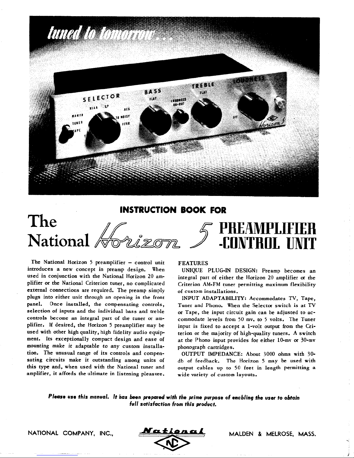
The
National
Horizon 5 preamplifier — control unit
introduces
a new
concept
in
preamp
design.
When
used
in
conjunction with
the
National
Horizon
20 am-
plifier
or the
National Criterion tuner,
no
complicated
external connections
are
required.
The
preamp
simply
plugs into either unit through
an
opening
in the
front
panel.
Once
installed,
the
compensating
controls,
selection
of
inputs
and the
individual
bass
and
treble
controls become
an
integral part
of the
tuner
or am-
plifier.
If
desired,
the
Horizon 5 preamplifier
may be
used with other high quality, high fidelity audio equipment.
Its
exceptionally compact design
and
ease
of
mounting make
it
adaptable
to any
custom
installa-
tion.
The
unusual range
of its
controls
and
compen-
sating
circuits
make
it
outstanding
among
units
of
this
type and,
when
used with
the
National tuner
and
amplifier,
it
affords
the
ultimate
in
listening
pleasure.
PREAMPLIFIER
-CONTROL
UNIT
FEATURES
UNIQUE
PLUG-IN DESIGN: Preamp becomes
an
integral part
of
either
the
Horizon
20
amplifier
or the
Criterion
AM-FM
tuner permitting
maximum
flexibility
of
custom
installations.
INPUT ADAPTABILITY: Accommodates
TV,
Tape,
Tuner
and
Phono.
When
the
Selector switch
is at TV
or
Tape,
the
input circuit gain
can be
adjusted
to ac-
commodate
levels
from
50 mv, to 5
volts.
The
Tuner
input
is
fixed
to
accept a 1-volt
output
from
the
Cri-
terion
or the
majority
of
high-quality tuners. A switch
at the
Phono input provides
for
either
10-mv
or
30-mv
phonograph
cartridges.
OUTPUT
IMPEDANCE: About 3000 ohms with
30-
db
of
feedback.
The
Horizon
5 may be
used with
output
cables
up to 50
feet
in
length permitting
a
wide
variety
of
custom
layouts.
Please
use
this manual.
It
has
been prepared
with
the
prime purpose
of
enabling
the
user
to
obtain
full
satisfaction
from
this product.
NATIONAL
COMPANY,
INC.,
MAIDEN & MELROSE, MASS.
EASE
OF
MOUNTING:
20
or the
Criterion
in. If
installed
cutout
is
required.
in
extremely compact
operation,
mating
operating
and
or
15-foot
an
connectors
and
tuner
or
lengths.
HARMONIC
output, 0.6%
(Normal
output
the
in a
custom wooden
Its
interconnecting
may be
signal
amplifier.
DISTORTION:
at 10 V
is 1.5
INTERMODULATION
0.31%
at
normal output
ratio
of 400 to
FREQUENCY
from
20
100 kc.
Flat
position.
HUM
AND
1.5
volt output when using
position
ed at the 10 mv
EQUALIZER
Selector
frequency
compensate
7000
cycles.
RESPONSE:
cycles
when
to 30
Bass
NOISE:
and
Hum
and 50 db or
phono
CONTROL:
switch provide seven combinations
turn over
for the
seven
When
used with
preamp
needs
only
cabinet
small
size
permits mounting
installations.
procured
voltages
This
Less
output
and
cable
cable
complete with
to
between
is
than 0.2%
1.5%
at 15 V
volts).
DISTORTION:
level
measured with
Flat
within
kilocycles
and
within
Treble controls
level
is 70 db or
the
Tape,
more
below
signal
position.
Positions
and
high-frequency rolloff
4 to 10 of the
most popular types
the
Horizon
to be
plugged
only
For
carry
the
remote
all the
preamp
available
at 1.5 V
output.
Less
a 4 to 1
±0.25
±1 db to
are in the
more
TV or
level
measur-
of
one
in 4
than
db
below
Tuner
low-
to
of re-
cording
lished
characteristics
Record Industry
(RIAA).
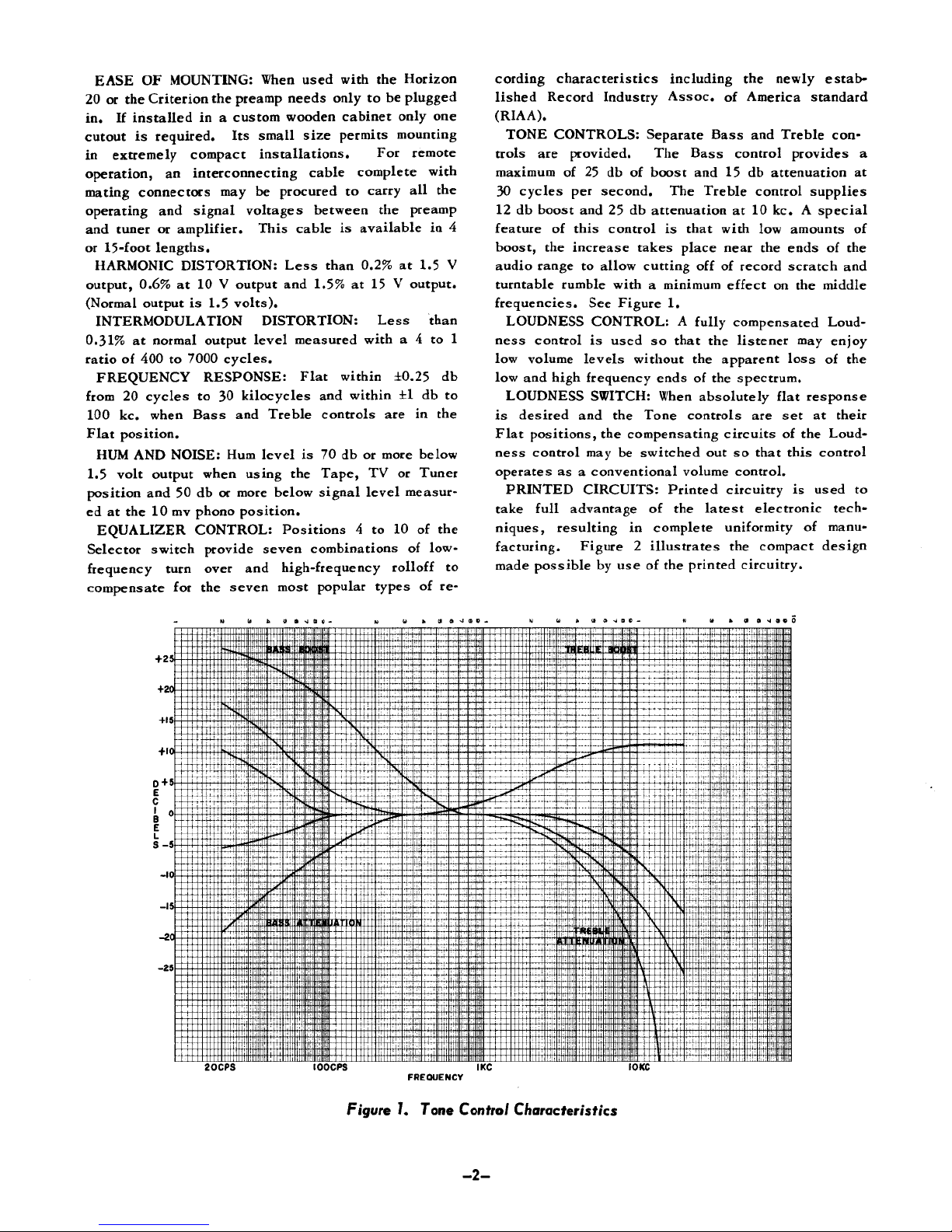
TONE
CONTROLS: Separate
trols
are
provided.
maximum
30
12
feature
boost,
audio range
turntable
frequencies.
LOUDNESS
ness
low
low
LOUDNESS
is
desired
Flat
ness
operates
PRINTED
take
of 25 db of
cycles
db
boost
of
the
rumble
control
volume
and
high
positions,
control
as a
full
advantage
per
second.
and 25 db
this
control
increase
to
allow cutting
See
CONTROL: A fully
is
used
levels
frequency
SWITCH:
and the
the
may be
conventional volume
CIRCUITS: Printed circuitry
niques, resulting
facturing.
made
Figure 2 illustrates
possible
by use of the
including
Assoc.
of
Bass
The
takes
Bass
boost
and 15 db
The
Treble control
attenuation
is
that with
place
control provides
at 10 kc. A
near
off of
with a minimum
Figure
1.
effect
compensated
so
that
the
listener
without
the
apparent
ends
of the
When
absolutely flat response
Tone controls
compensating circuits
switched
of the
in
complete
out so
latest
uniformity
the
printed circuitry.
the
newly
estab-
America standard
and
Treble
con-
attenuation
supplies
special
low
amounts
the
ends
of the
record scratch
on the
and
middle
Loud-
may
enjoy
loss
of the
spectrum.
are set at
of the
that
this
their
Loud-
control
control.
is
used
electronic
of
tech-
manu-
compact design
a
at
of
to
20CPS
IOOCPS
Figure
FREQUENCY
1.
Tone
Contra/
-2-
IOKC
Characteristics
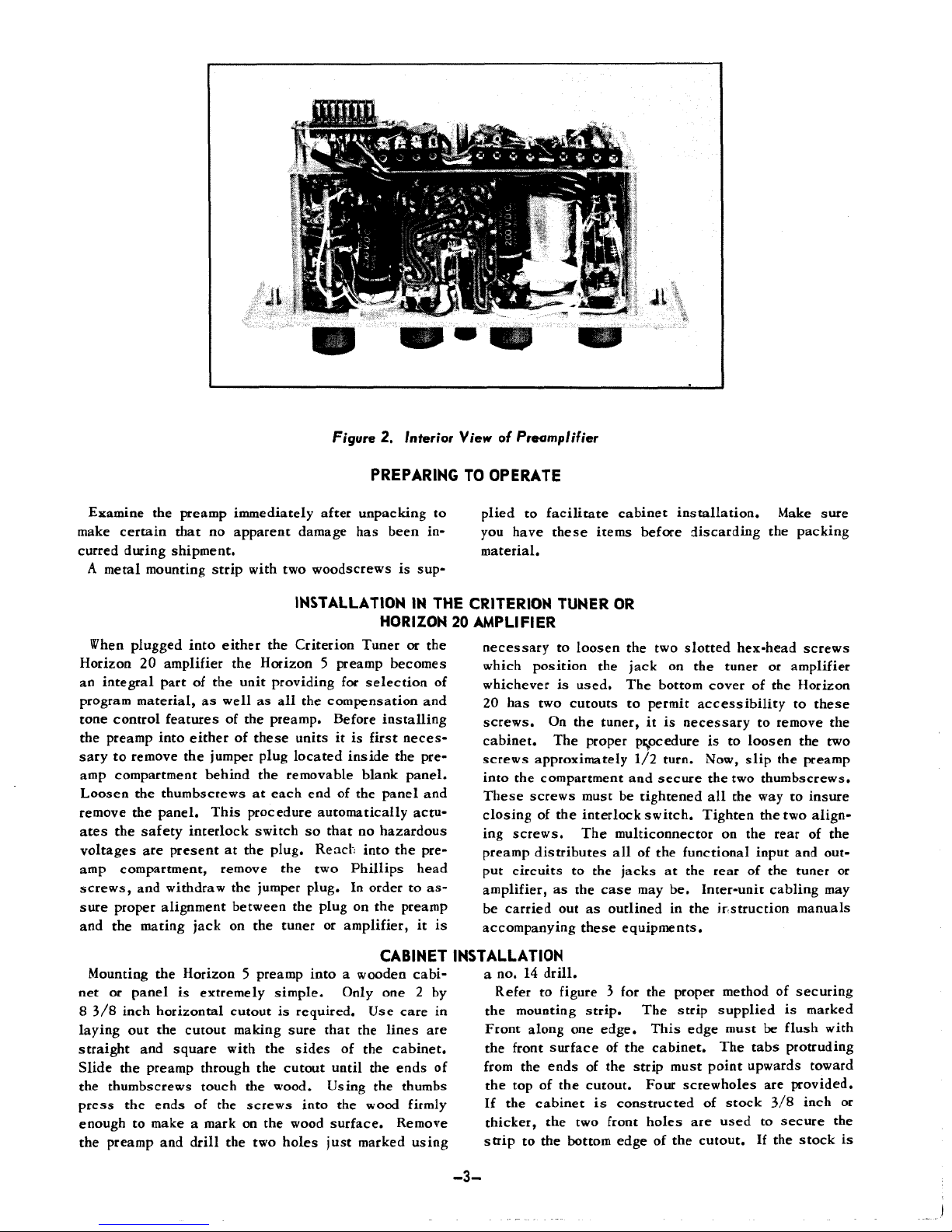
Figure
2.
Interior
View
of
Preamplifier
PREPARING
TO
OPERATE
Examine
the
preamp
immediately
after
unpacking
to
make
certain that
no
apparent damage
has
been
in-
curred
during shipment.
A
metal
mounting
strip
with
two
woodscrews
is
sup-
INSTALLATION
IN THE
HORIZON
20
When
plugged into either
the
Criterion Tuner
or the
Horizon
20
amplifier
the
Horizon 5 preamp
becomes
an
integral part
of the
unit providing
for
selection
of
program
material,
as
well
as all the
compensation
and
tone control features
of the
preamp. Before installing
the
preamp into either
of
these
units
it is
first
neces-
sary
to
remove
the
jumper
plug located
inside
the
pre-
amp
compartment behind
the
removable blank
panel.
Loosen
the
thumbscrews
at
each
end of the
panel
and
remove
the
panel.
This
procedure automatically actu-
ates
the
safety interlock switch
so
that
no
hazardous
voltages
are
present
at the
plug.
Reach
into
the
pre-
amp
compartment, remove
the two
Phillips
head
screws,
and
withdraw
the
jumper
plug.
In
order
to as-
sure proper alignment between
the
plug
on the
preamp
and
the
mating jack
on the
tuner
or
amplifier,
it is
plied
to
facilitate cabinet
installation.
Make
sure
you
have
these
items before discarding
the
packing
material.
CRITERION
TUNER
OR
AMPLIFIER
necessary
to
loosen
the two
slotted
hex-head screws
which
position
the
jack
on the
tuner
or
amplifier
whichever
is
used.
The
bottom cover
of the
Horizon
20
has two
cutouts
to
permit
accessibility
to
these
screws.
On the
tuner,
it is
necessary
to
remove
the
cabinet.
The
proper
procedure
is to
loosen
the two
screws approximately
1/2
turn. Now,
slip
the
preamp
into
the
compartment
and
secure
the two
thumbscrews.
These screws
must
be
tightened
all the way to
insure
closing
of the
interlock switch. Tighten
the two
align-
ing
screws.
The
multiconnector
on the
rear
of the
preamp
distributes
all of the
functional input
and
out-
put
circuits
to the
jacks
at the
rear
of the
tuner
or
amplifier,
as the
case
may be.
Inter-unit cabling
may
be
carried
out as
outlined
in the
instruction
manuals
accompanying
these
equipments.
CABINET
Mounting
the
Horizon 5 preamp
into a wooden
cabi-
net or
panel
is
extremely
simple.
Only
one 2 by
8 3/8
inch horizontal cutout
is
required.
Use
care
in
laying
out the
cutout
making
sure that
the
lines
are
straight
and
square with
the
sides
of the
cabinet.
Slide
the
preamp through
the
cutout until
the
ends
of
the
thumbscrews touch
the
wood. Using
the
thumbs
press
the
ends
of the
screws into
the
wood
firmly
enough
to
make a mark
on the
wood
surface.
Remove
the
preamp
and
drill
the two
holes
just
marked
using
INSTALLATION
a no. 14
drill.
Refer
to
figure
3 for the
proper method
of
securing
the
mounting
strip.
The
strip supplied
is
marked
Front along
one
edge.
This
edge must
be
flush with
the
front
surface
of the
cabinet.
The
tabs
protruding
from
the
ends
of the
strip must point upwards toward
the top of the
cutout. Four screwholes
are
provided.
If
the
cabinet
is
constructed
of
stock
3/8
inch
or
thicker,
the two
front
holes
are
used
to
secure
the
strip
to the
bottom edge
of the
cutout.
If the
stock
is
-3-
 Loading...