

National Epicenter Single End Panel Assembly Instruction Manual
Drill
Note: For better clarity, this Instruction does not always show the undersurface
pedestal or other undersurface components.
Assembly Instruction
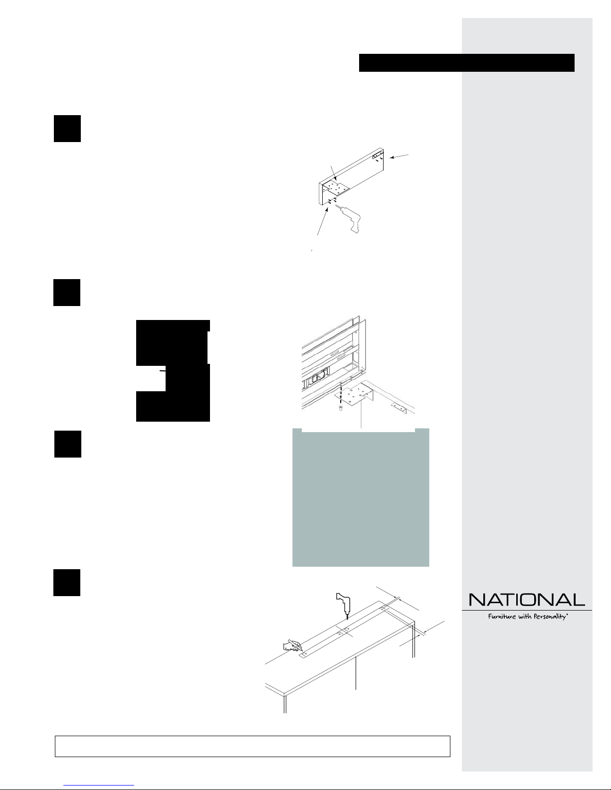
On a smooth clean dry surface place the
1
end panel. Attach the Epicenter bracket
ush to the top of the end panel, with
three (3) #10 x 1" pan head screws. Place
Figure A
Epicenter
Bracket
the L-bracket on the end panel, attach
with two (2) #8 x 5/8" pan head screws
(Figure A).
NOTE: Epicenter bracket comes in separate package from the end panel. If two
end panels are used, attach epicenter
#10 x 1" Pan Head Screws
brackets to the epicenter rst, then
center and attach each end panel.
Determine the proper end and placement of the epicenter bracket per your conguration
to attach the end panel to the epicenter. Attach with (2) #10-32 x 3/4" screws and (2)
2
#10-32 wellnuts. (See Figures A and B). Note: Hand start before fully fastening.
Use 10-32 screws
through C channel
Insert Wellnut
Into Bracket
Figure A
If wellnut doesn’t fit
into bracket, use
wellnut as a nut
underneath bracket.
Figure B
In the desired location, place 3" wide
3
masking tape where the end panel and
epicenter intersects with the lower
unit. Using a pencil mark the location
of the ends and sides of the end panel
(Figure C). NOTE: If two end panels are
used, mark each one.
#8 x 5/8"
Pan Head
Screws
Figure C
Epicenter Single
End Panel
Recommended Tools
• Drill with 5/16" bit
• Phillips head screwdriver
• Tape Measure
• 3" wide masking tape
• Pencil
Package Contents Qty.
• End Panel 1
• #8 x 5/8" Pan Head
Screws 4
• 1/4-20 x 2 1/2" Flat Head
Machine Screws 2
• L Bracket 1
2nd Package Contents Qty.
• Epicenter Bracket 1
• #10 x 1" Pan Head
Screw 7
• #10-32 x 3/4" Screws 2
• #10-32 Wellnut 2
Using a tape measure and pencil, mark the
locations shown in (Figure D) measuring
4
from the corners marked in step #3 for
boring holes for two (2) 1/4-20 x 2 1/2"
Flat Head Machine Screws per end panel.
Drill two (2) 5/16" holes through the
lower worksurface per end panel. If (2)
end panels are used mark and bore 4
holes.
Proper product installation, in accordance with these instructions, is the responsibility of the installing agent. If you have any
questions concerning these instructions, please call National Customer Service 800.482.1717.
Drill 5/16"
holes.
37/64"
Figure D
1 31/64"
Telephone 800.482.1717
Fax 812.482.8800
www.NationalOfficeFurniture.com
Part #2439929
Rev,B
Printed in U.S.A
© 2014 Kimball International, Inc.
Assembly Instruction
Epicenter Single
End Panel
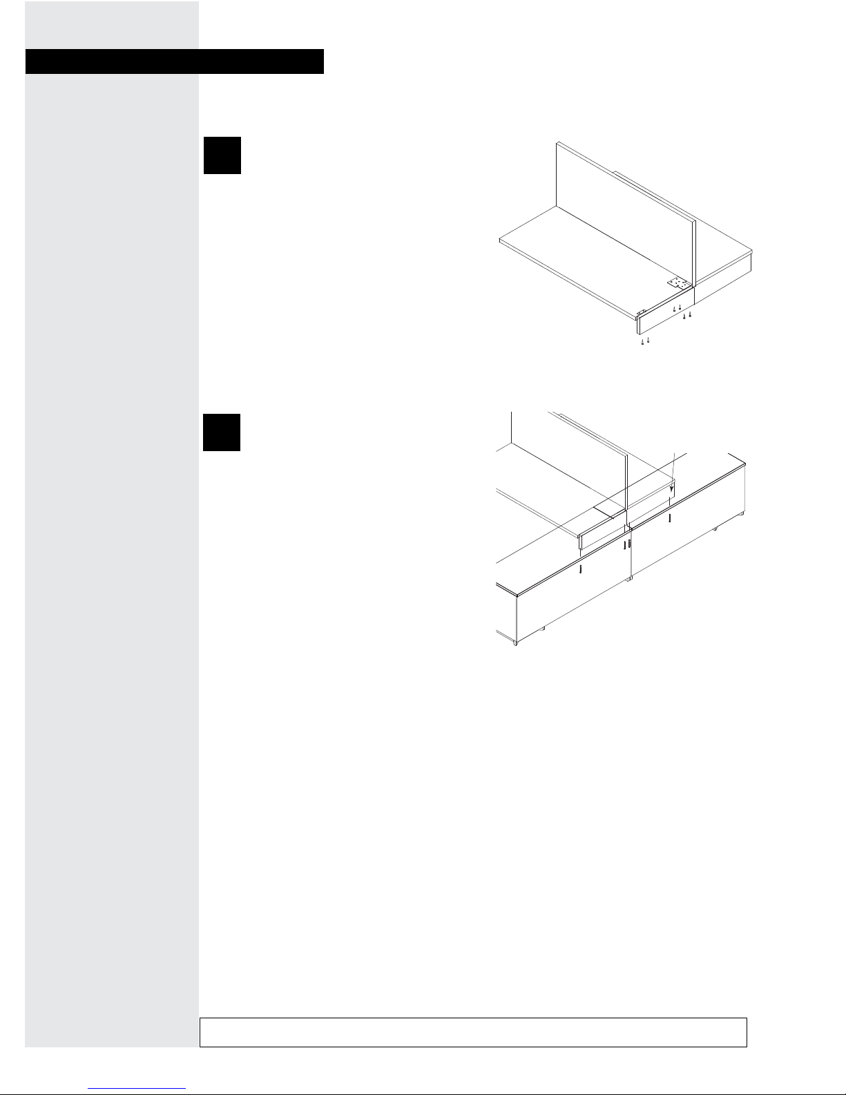
Attach the worksurface to the epicenter
5
bracket with four (4) #10 x 1" pan head
screws. Attach the L brackets with two
(2) #8 x 5/8" pan head screws (Figure
E).
NOTE: If two end panels are used repeat
process for the other end panel.
With the upper and lower units
6
positioned in the desired locations,
install two (2) 1/4-20 x 2 1/2" Flat
Head Machine screws through the
lower worksurface into the end
panel (Figure F).
Figure E
Figure F
#8 x 5/8"
Pan Head
Screws
NOTE: Repeat
process if two end
panels are used.
#10 x 1" Pan
Head Screws
NOTE: Repeat
process if two end
panels are used.
NOTE: If two end panels are used
repeat process for the other end
panel.
Two (2) 1/4-20 x 2 1/2" FH
Machine Screws
Proper product installation, in accordance with these instructions, is the responsibility of the installing agent. If you have any
questions concerning these instructions, please call National Customer Service 800.482.1717.
 Loading...