

National DM-52 Instructions Manual
National Optical & Scientific Instrument Inc.
6508 Tri-County Parkway
Schertz, Texas 78154
Phone (210) 590-9010 Fax (210) 590-1104
INSTRUCTIONS FOR
MODEL DM-52
COMPOUND BIOLOGICAL MICROSCOPE
WITH DIGITAL CAMERA
(For microscope operation only. Camera operation covered in separate
supplement on disc.)
HOW TO USE YOUR MICROSCOPE SERIAL NUMBERS
1. Microscope serial number
: This number (etched on inside of small ledge
immediately behind stage plate) is the number under which your warranty
is registered.
2. Microscope DM number: This number (found on a white sticker on the
bottom of the microscope) is used for logging on the Motic web site, which
gives you the ability to download free software upgrades. This number is
also used to register the software when loading on the computer for the
first time.
Copyright © 1/18/05
National Optical & Sc i ent i fic Instrument I nc.
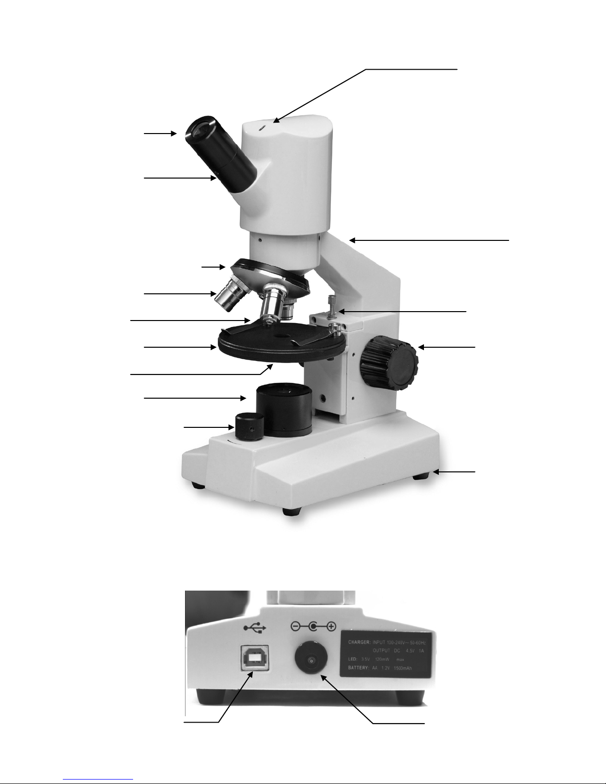
LED indicator light
Arm
Safety rack stop
Focusing knob
Rubber feet
LED illuminator
Rotating stage
In stage lens
Objective lens
Objective turret (nosepiece)
Eyepiece tube
DC recharging
USB port
Stage clips
Eyepiece
(ocular lens)
On/Off switch with
rheostat intensity control
socket

3
About the Digital Microscope
The manual for your new digital microscope is in two parts. This first part describes the basic
nomenclature and functions of the microscope, which can be used as a fully functional microscope,
independent of the camera. The second part is the Motic Image Quick Start Guide located on you CD,
which provides detailed documentation for installation and operation of the Motic software. In order to
achieve optimum results, it is important that you carefully read these documentation manuals before
operating your microscope or camera.
UNPACKING
1. Your microscope is packed with the following components, all of which have been checked at the
factory. Carefully remove all components and check against this list. Retain styrofoam container in
case microscope must be transported or returned to factory for any reason.
A. Microscope, with three objective lenses already installed.
B. WF 10x eyepiece.
C. Instruction manual
D. Moti c Educator CD
E. Motic Play CD.
F. Calibration slide
G. Automatic switching recharger operates on 100 to 240 volts AC 50/60 Hz.
H. USB cable (for connecting microscope to computer)
I. 0.9mm “L” type hex key wrench (for locking eyepiece and replacing LED lamp)
J. Dustcover
K. Warranty card
2. If it becomes necessary to ship the microscope for any reason, repack it in the styrofoam container,
and then pack the styrofoam in another corrugated shipping container for optimum protection. Use of
the styrofoam alone will not provide adequate protection in transit, and will void your warranty.
DESCRIPTION OF COMPONENTS
1. LED INDICATOR LIGHT: Indicates if camera is on. This light will not come on, nor will this light be
on, until microscope is connected to computer with USB cable and software activated. This
connection occurs later, and is covered in software manuals.
2. EYEPIECE (ocular lens): Lens closest to the eye, magnifies the primary image formed by the
objective lens.
3. EYEPIECE TUBE: Tube with locking setscrew, holds and secures eyepiece to microscope.
4. OBJECTIVE TURRET (nosepiece): Revolving turret which holds objective lenses, permits changes of
magnification by rotating different powered objective lenses into optical path.
5. OBJECTIVE LENS: Lens closest to the object being viewed, forms first magnified image of the
specimen.
6. STAGE CLIPS: Two locked-on clips hold specimen slide in place on stage.
7. ROTATING STAGE: Platform of the microscope where the specimen slide is placed. Stage rotates
360 degrees and glides left to right permitting easy manipulation of the specimen slide.
8. IN STAGE LENS: A specially designed diffuser lens, fixed in center of stage, diffuses light rays from
LED illuminator to evenly fill the back lens element lens to improve image resolution.
 Loading...