

National DCX-205-RLED Instructions Manual

(Manual for microscope and WiFi camera operation only)
Microscope serial number: This number is on a label located under the base of the microscope.
It is the number under which your warranty is registered.
Copyright © 6/13/2013
National Optical & Scientific Instrument Inc.
National Optical & Scientific Instruments Inc.
6508 Tri-County Parkway
Schertz, Texas 78154
Phone (210) 590-9010 Fax (210) 590-1104
INSTRUCTIONS FOR
MODEL DCX-205-RLED
COMPOUND BIOLOGICAL MICROSCOPE
WITH WIFI CAMERA
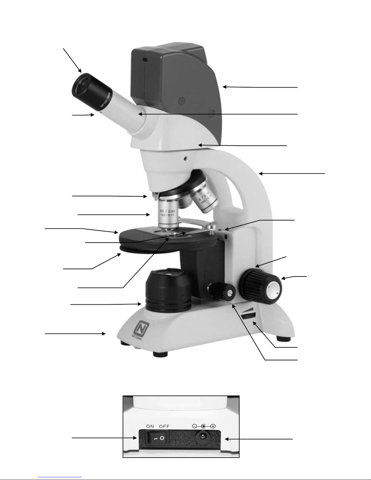
Eyepiece tube
Head of microscope
Arm
Objective turret
(nosepiece)
Objective lens
Linked single control
Condenser lens
Stage
Illuminator field
Base
Tension adjustment
Coarse focus
Fine focus knob
Rheostat control
Safety rack stop
set screw
Eyepiece
locking screw
Recharging socket
Eyepiece
Camera housing
(ocular lens)
stage clips
Disc
diaphragm
lens housing
knob
On/Off Switch

For optimum viewing satisfaction, follow these simple procedures. Nomenclature used to describe components and
controls can be identified by referring to the diagram at left.
UNPACKING
1. Carefully remove microscope, WF10x eyepiece, dustcover, 2mm “L” hex wrench (for rack stop adjustment), 0.90mm
“L” hex key wrench (for eyepiece socket set screw and for lamp replacement), USB Cord, microscope power adapter
(4.5v), USB power adapter (5V), and calibration slide. Always handle and move microscope by securely holding the
arm of microscope. Avoid touching any of the lens surfaces while handling the microscope. Dust, dirt, or fingerprints
can damage the delicate lens surfaces or adversely affect image quality.
2. Examine packing material before you discard it. Retain the styrofoam container in case you need to transport,
store, or return the microscope for service. If it becomes necessary to ship the microscope for any reason, pack it
in the styrofoam container, and then pack the styrofoam in another corrugated shipping container for optimum
protection. Use of the styrofoam alone will not provide adequate protection in transit, and will v oid your warr ant y.
MOTICONNECT APP DOWNLOAD
1. In preparation for using the DCX-205-RLED, you may wish to download and install the free MotiConnect app. The
MotiConnect app can be downloaded from either the Google Play Store or App le App Stor e, depe nd ing on whether
you are using an Android or Apple device.
2. Instructions for the MotiConnect app can be found within the application through help butt on. Further ins tr ucti on
available from Motic and National Opt ic al Yo u Tube pages online.
3. Your WiFi camera also has built in software, which is accessible by typing in the cameras IP address in your web
browser. These instructions are covered in WiFi Camera Operation section of this manual.
4. If you would like to connect the WiFi camera to a wireless enabled laptop or computer, go to the National Optical
website. On the website, you will need to register your product first and then you will be able to download the Motic
Images software. Instructions on connecting to your wireless enabled laptop or desktop are covered in the Wifi
Camera Operation section of this manual.
DESCRIPTION OF COMPONENTS
1. EYEPIECE (ocular lens) Lens closest to the eye, magnifies the primary image formed by the objective lens. The
eyepiece is equipped with a “pointer” that rotates as the eyepiece is turned.
2. OBJECTIVE TURRET (nosepiece) Revolving turret which holds objective lenses, permits changes of magnification
by rotating different powered objective lenses into optical path.
3. OBJECTIVE LENS Lens closest to the object being viewed, forms first magnified image of the specimen.
4. STAGE CLIPS Two linked single control locked-on clips hold specimen slide in place on stage.
5. STAGE Floating platform of the microscope where the specimen slide is placed.
6. CONDENSER LENS A specially designed condenser lens, fixed in center of stage, condenses light rays from
substage illumination and fills the back lens element of objective lens to improve image resolution.
7. DISC DIAPHRAGM Rotating disc located below stage with holes of various apertures, designed to help achieve
optimum resolution of the objective lens. Larger apertures used for higher magnifications, and smaller apertures used
for lower magnifications.
8. SAFETY RACK STOP When properly adjusted, it controls maximum upward travel of stage. Prevents higher power
objectives from breaking specimen slides, prevents damage to objective lenses. This stop has been pre-adjusted at
the factory.
9. FOCUSING KNOBS Coarse focusing knobs (larger knobs) located on each side of arm, raise or lower stage to
bring specimen image into focus. Fine focus knobs (smaller knobs) located on each side of arm permit more precise
image adjustment.
3
 Loading...