

National DC5-163 Instructions Manual

National Optical & Scientific Instruments Inc.
Phone (210) 590-9010 Fax (210) 590-1104
COMPOUND BIOLOGICAL MICROSCOPE
(For microscope operation only. Camera operation and installation covered in separate
HOW TO USE YOUR MICROSCOPE SERIAL NUMBERS
1.
Microscope serial number: This number (etched on back arm of microscope) is the
number under which your warranty is registered.
2.
Microscope DM number: This number (found on a white sticker on the bottom of the
microscope) is used for logging on the Motic web site, which gives you the ability to
download free software upgrades.
3.
Motic CD DM number: This number is to be used to register the software when
loaded on the computer for the first time.
Copyright © 8/5/04
National Optical & Scientific Instrument Inc.
11113 Landmark 35 Drive
San Antonio, Texas 78233
INSTRUCTIONS FOR
MODEL DC5-163
WITH DIGITAL CAMERA
supplement to documentation)
r
A
X
f
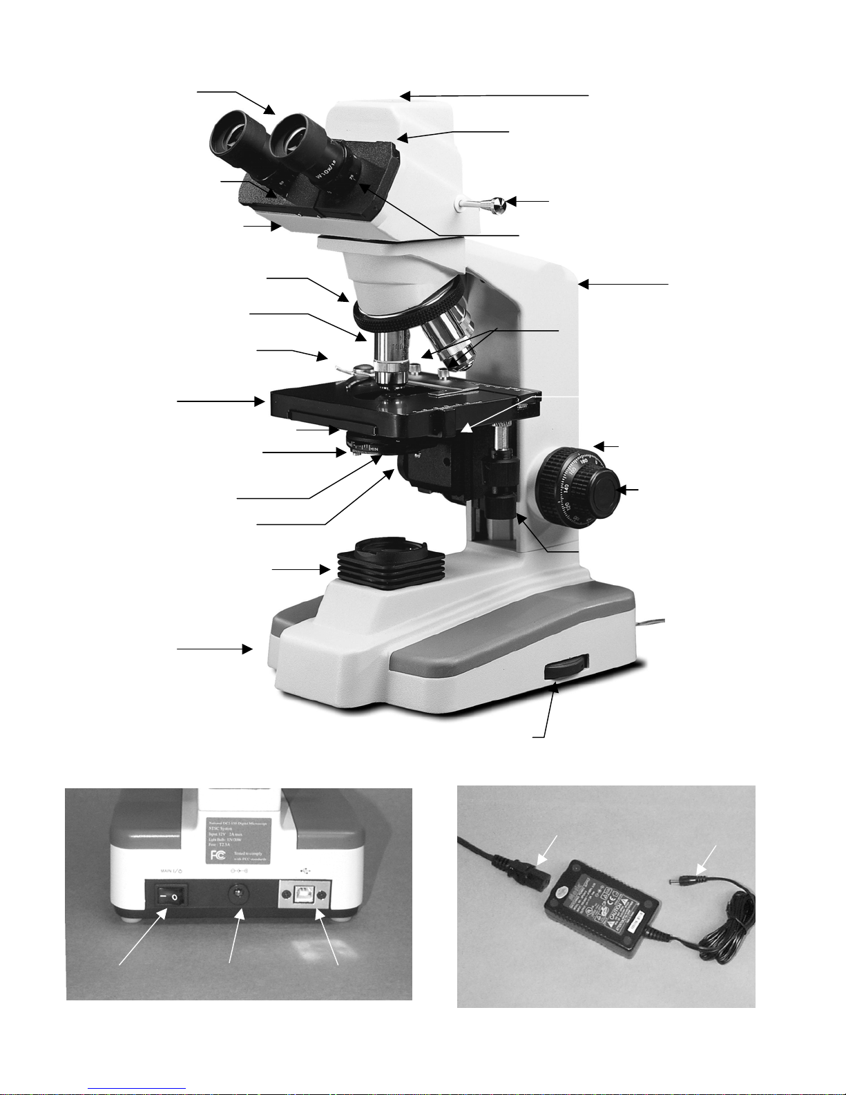
Eyepiece
Interpupillary
scale
LED indicator light
Sliding interpupillary adjustment
grips located on both left and
right side of diopter scale
Three position sliding rod
Viewing head of
microscope
Revolving nosepiece
Objective lenses
Specimen holder
(mechanical stage)
Stage
Abbe condenser 1.25 N.A.
Iris diaphragm lever
Filter holder
Control knob for
Abbe condenser
Illuminator condenser
Mark on side of eyepiece tube
for indexing diopter reading
rm
Knurled locking screws
for securing specimen
(
holder to stage)
Abbe condense
locking screw
Coarse focus
knob
Fine focus
knob
Knobs controlling
and Y movement o
mechanical stage
Power
On/Off
Main
Switch
Base
Camera
On/Off
12 volt
DC input
Tension
adjustment knob
USB output
terminal
Light intensity
control knob
Detachable power supply cord
100v-240v, 50H/60H input
12 volt DC switching power supply
12 volt
DC output
About the Digital Microscope
The manual for your new digital microscope is in three parts. This first part describes the basic nomenclature and
functions of the microscope, which can be used as a fully functional microscope, independent of the camera. The
second part is the “Important Supplement to Documentation” describing loading of your CD. The third part is the Motic
Images Quick Start Guide located on your CD, which provides detailed documentation for installation and operation of
the Motic Images software. In order to achieve optimum results, it is important that you carefully read these
documentation manuals before operating your microscope or camera.
UNPACKING
1. Your microscope is packed with the following components, all of which have been checked at the factory.
Carefully remove all components and check against this list. Retain styrofoam container in case microscope must
be transported or returned to factory for any reason.
A. Microscope body with 1.25 N.A. Abbe condenser and iris diaphragm
B. Two WF10x eyepieces
C. Two rubber eyecups
D. Four objective lenses: DIN 4x, 10x, 40xR, 100xR oil immersion
E. Three filters: blue, green, yellow
F. Specimen holder for mechanical stage
G. 12VDC switching power supply, operates on 100v-240v, 50H/60H
H. Power cord
I. CD Motic Images software
J. Two instruction manuals: this one and separate supplement documentation
K. Calibration slide
L. USB 2.0 PCI card with driver CD and user manual
M. USB cable (for connecting to computer)
N. Dustcover
O. Warranty card
2. If it becomes necessary to ship the microscope for any reason, repack it in the styrofoam container, and then pack
the styrofoam in another corrugated shipping container for optimum protection. Use of the styrofoam alone will not
provide adequate protection in transit, and will void your warranty.
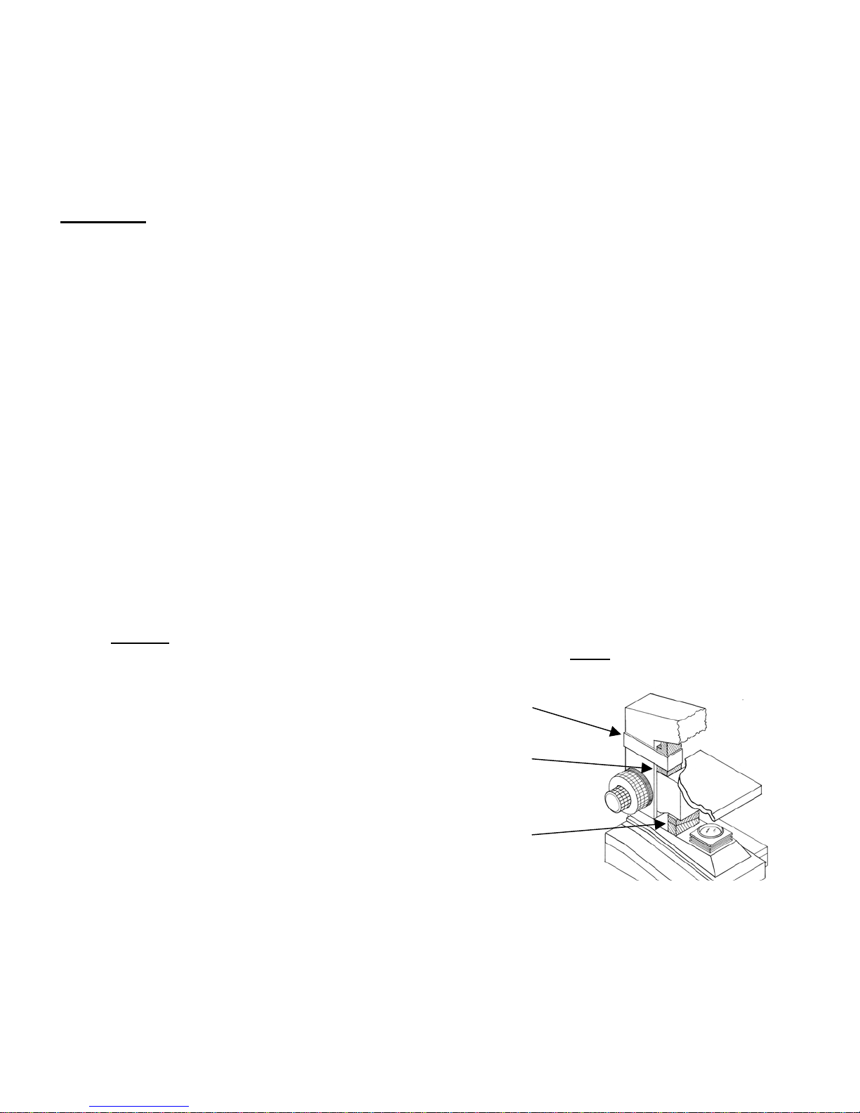
NOTICE: To protect focus mechanism during shipment, two black plastic wedges (b) and one black plastic
A.
block (c) are inserted at strategic points as indicated. These plastic parts
MUST be removed prior to operating
microscope. Failure to do so will result in damage to focusing mechanism and will void your warranty.
(a)
1. Remove two black velcro straps (a).
2. Remove wedge (b) by pulling apart the
two parts of wedge in opposite directions.
3. Lower stage by rotating coarse focus
(c)
knob in counter-clockwise direction.
in counter-clockwise direction
4. Remove block (c) from stand.
5. These components should be retained
(b)
with styrofoam container.
B. Carefully remove from the stand all tape and packing material used to protect microscope components during
shipment. Remove black objective plugs from nosepiece.
C. Unwrap components, making certain that lens surfaces do not come in contact with dust, dirt, fingerprints.
Damage to optical surfaces can result from such contaminants, and reduce image quality.
3
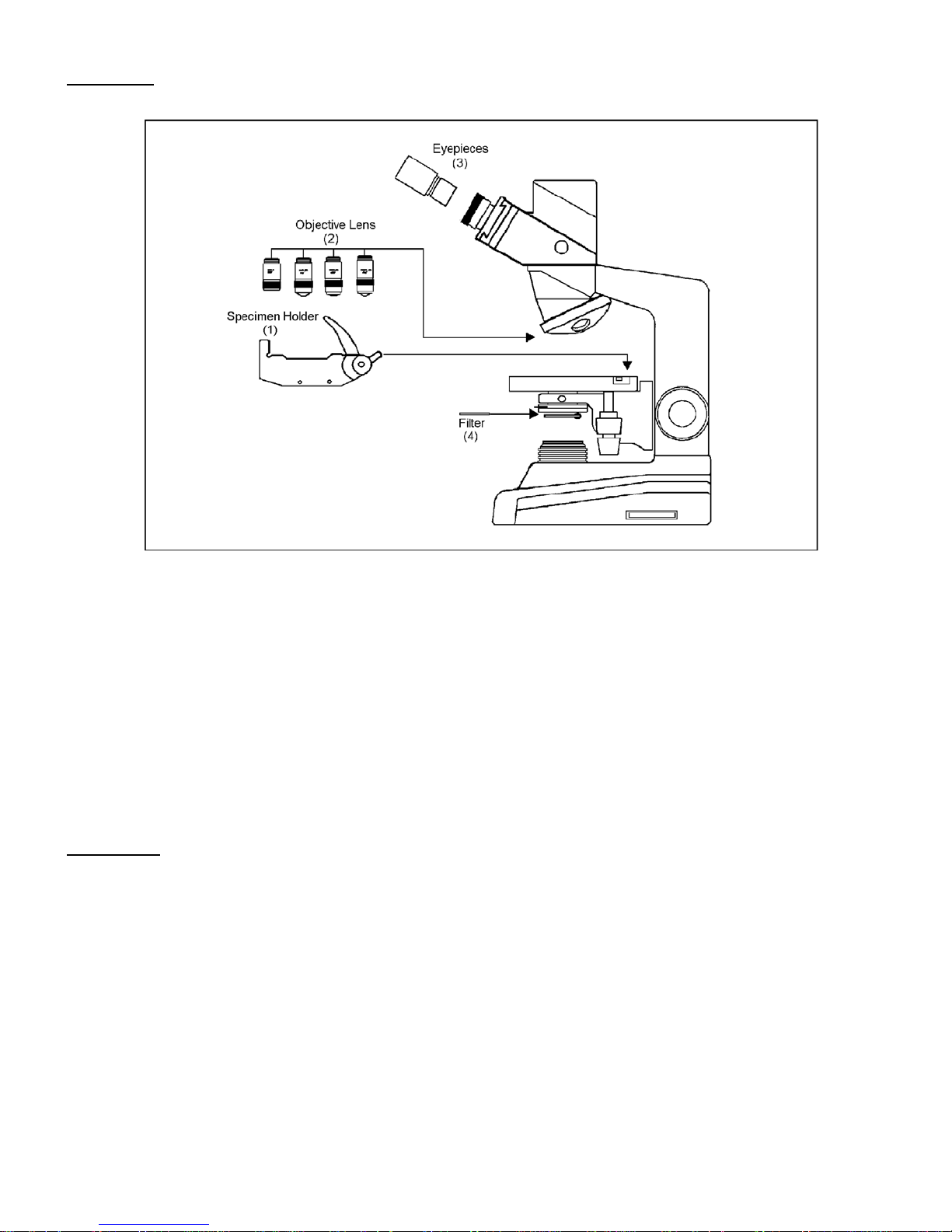
ASSEMBLY
1. Specimen holder: Rotate coarse focusing knob to move stage platform to its lowest position. Remove two knurled
screws from mechanical stage platform. Place specimen holder on stage and using the two knurled locking
screws, attach holder to mechanical stage.
2. Objectives: With stage platform located at its lowest position. Screw all the objectives into the nosepiece, making
certain to mount them in consecutive order 4x, 10x, 40x, 100x.
3. Eyepieces: Remove the dust caps from eyepiece tubes. Avoid touching any lens surface. Insert eyepieces into
the eyepiece tubes.
4. Filters: Swing out filter holder and insert 32mm diameter blue filter.
OPERATION
Your microscope is fully functional as a standard microscope. The following instructions apply to operation of the
microscope. Refer to “Supplement to Documentation and Quick Start Guide located on your CD” for installation of the
software and operation of the camera.
1. Illumination.
A. Before operating microscope, adjust intensity control located on side of base to the minimum position.
This should be done prior to each time light is turned on or off. This will extend bulb life.
B. Insert power plug into 12VDC switching power converter, then insert plug on other end of converter into power
jack on back of microscope base. Note that the 12VDC converter will operate on either 120v or 240v current,
50 hertz or 60 hertz, eliminating the need for any other transformer.
4
 Loading...