

National DC4-156-S User Manual

National Optical & Scientific Instrument Inc.
6508 Tri-County Parkway
Schertz, Texas 78154
Phone (210) 590-9010 Fax (210) 590-1104
INSTRUCTIONS FOR
MODEL DC4-156-S
COMPOUND BIOLOGICAL MICROSCOPE
WITH DIGITAL CAMERA
(For microscope operation only. Camera operation covered in separate instructions)
HOW TO USE YOUR MICROSCOPE SERIAL NUMBERS
1. Microscope serial number: This number (etched on back arm of microscope) is
the number under which your warranty is registered.
2. Microscope DM number: This number (found on a white sticker on the bottom
of the microscope) is used for logging on the Motic web site, which gives you the
ability to download free software upgrades.
Copyright © 10/19/04
National Optical & Sci entific Instrum ent Inc.
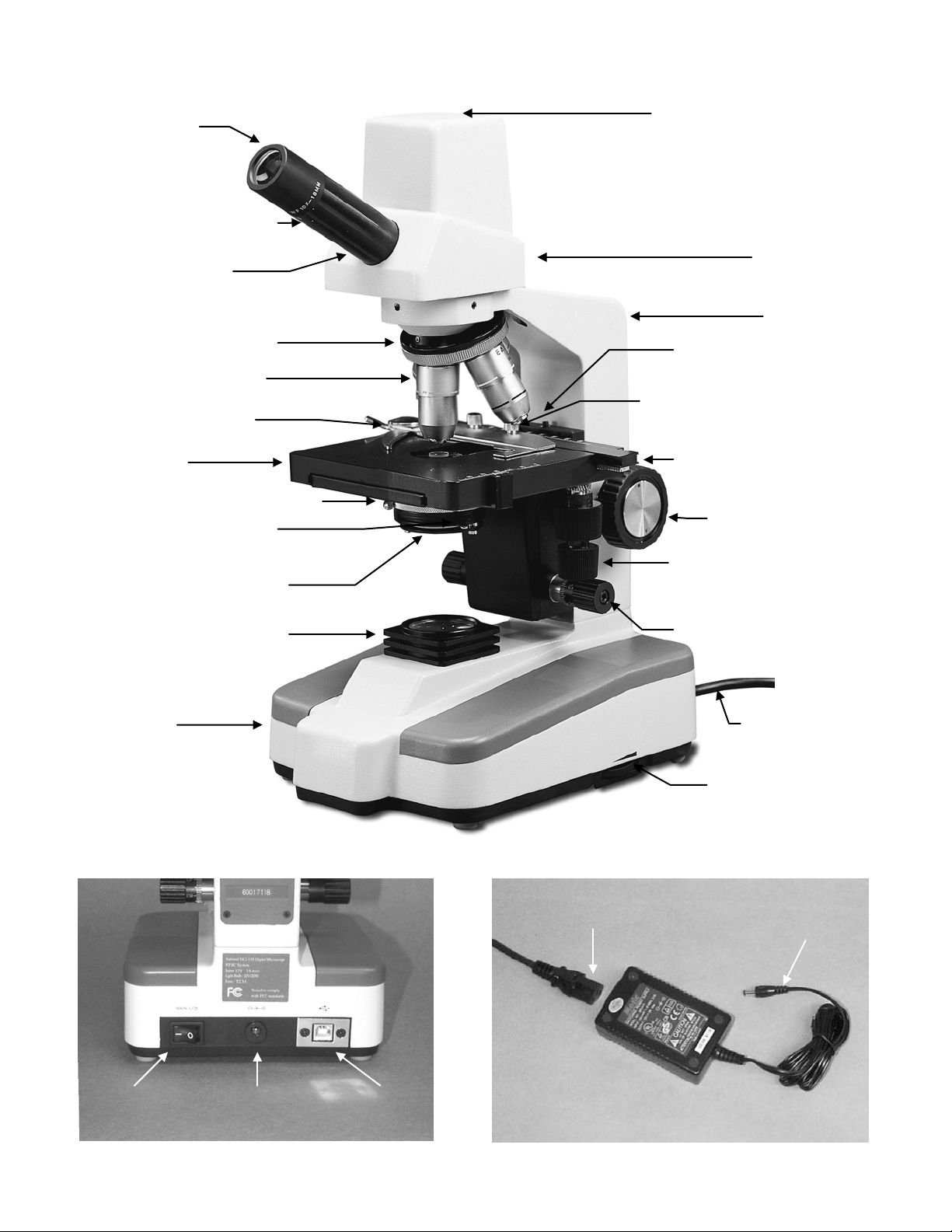
LED indicator light
Illuminator condenser
Specimen holder
Fine focus knob
USB output
12 volt
DC input
Main
12 volt DC switching power supply
Detachable power supply cord
Rack stop adjustment
Knobs controlling
X & Y movement of
Coarse focus
Tension adjustment
(behind focus
Knurled locking screws
Light intensity
Eyepiece
Eyepiece locking set
screw
Eyepiece tube
Revolving nosepiece
Objective lenses
(mechanical stage)
Head
Arm
screw
(for securing specim en
holder to stage)
Stage
Abbe condenser 1.25 N.A.
Iris diaphragm lever
Swing-out filter holder
Base
collar
knob on left side)
knob
mechanical stage
Power cord
control knob
Switch
terminal
100v-240v, 50H/60H input
12 volt
DC output

3
About the Digital Microscope
Your new digital microscope incorporates a built in camera that utilizes ultra high-speed data transmission made
possible through a simple plug and play USB 2.0 cable. In order to achieve optimum results, it is important that
you carefully read both this and the software instructions located on Motic disc before operating your microscope
or camera.
UNPACKING
1. Your microscope is packed with the following components, all of which have been checked at the factory.
Carefully remove all components and check against this list. Retain styrofoam container in case microscope
must be transported or returned to factory for any reason.
A. Microscope, with WF10x eyepiece, four objective lenses, 1.25 N.A. Abbe condenser, specimen holder
already installed.
B. Instruction manual
C. CD Motic Images software (instructions for software on disc)
D. Calibration slide
E. 12VDC switching power supply, operates on 100v-240v, 50H/60H
F. Power cord
G. USB 2.0 cable (for connecting to computer)
H. Rubber eyecup
I. Blue filter and frosted neutral filter.
J. 2mm “L” type key wrench (for rack stop adjustment)
K. 0.9mm “L” type key wrench (for tension adjustment collar)
L. Dustcover
M. Warranty card
2. Retain Styrofoam container in case microscope must be transported or returned to factory for any reason. If
it becomes necessary to ship the microscope for any reason, repack it in the styrofoam container, and then
pack the styrofoam in another corrugated shipping container for optimum protection. Use of the styrofoam
alone will not provide adequate protection in transit, and will void your warranty.
DESCRIPTION OF COMPONENTS
1. LED INDICATOR LIGHT: Indicates if camera is on, power supplied by USB.
2. EYEPIECE (ocular lens): Lens closest to the eye, magnifies the primary image formed by the objective
lens.
3. OBJECTIVE TURRET (nosepiece): Revolving turret which holds objective lenses, permits changes of
magnification by rotating different powered objective lenses into optical path. Reverse position permits
easier access to stage when positioning specimen slides.
4. OBJECTIVE LENS: Lens closest to the object being viewed, forms first magnified image of the specimen.
5. MECHANICAL SPECIMEN HOLDER: Permits precise, mechanical manipulation of the specimen slide.
6. STAGE: Platform of the microscope where the specimen slide is placed.
7. CONDENSER: A 1.25 N. A. Abbe condenser lens positioned under center of stage, condenses light rays
from substage illumination and fills the back lens element of objective lens to improve image resolution.
8. IRIS DIAPHRAGM: Attached to bottom of Abbe condenser, controls aperture of light by moving control lever
left or right.
9. SWING OUT FILTER HOLDER: Used for holding 32mm filters.
 Loading...