

National 167, 168, DC20-169, 169-BTW1, 169 Instructions For

National Optical & Scientific Instruments Inc.
6508 Tri-County Parkway
Schertz, Texas 78154
Phone (210) 590-9010 Fax (210) 590-1104
INSTRUCTIONS FOR
167, 168, 169, DC20-169, and 169-BTW1 Series
COMPOUND BIOLOGICAL MICROSCOPES
Copyright © 11/4/2016
National Optical & Scientific Instrument Inc.

2
Table of Contents
Introduction / Unpacking 167, 168 and 169 ............................................................................................... 3
Assembly .................................................................................................................................................... 4
Operation .................................................................................................................................................... 5
Installing C-Mount Camera / Maintenance ................................................................................................ 7
Introduction to the DC20-163 .................................................................................................................... 9
Assembly .................................................................................................................................................. 10
Camera Controls and Ports / Connecting Camera to HD Ready Device ............................................... 11
On Screen Display / On Screen Display Control / Live Image and Capture Controls .......................... 13
Image Adjustment Controls ..................................................................................................................... 13
Connecting to Computer / Motic Images Software - PC Full Help Menu ............................................. 15
Motic Images Imaging Module – PC Full Help Menu ............................................................................. 15
Motic Images Software – MAC Full Help Menu ...................................................................................... 16
Introduction to the 169-BTW1 ................................................................................................................. 18
169-BTW1 Assembly / Connecting Camera to Tablet ............................................................ 19
Tablet Operation / Power Management ................................................................................................... 20
Tablet Accessories ................................................................................................................................... 21
Camera Switches and Ports / Connecting to WiFi device / Connecting to WiFi Computer ................. 22
Connecting to Existing WiFi Network ...................................................................................................... 23
Connecting to Networked BTW with MotiConnect App ........................................................................ 25
Connecting to Networked BTW with Motic Images ................................................................................ 27
Tablet Software / MotiConnect Overview / Help Button ......................................................................... 29
Calibration / Transferrig Images to your computer .............................................................................. 30
Motic Images 2.0 ...................................................................................................................................... 31
Motic Images 3.0 ...................................................................................................................................... 33
926 Phase Kit ................................................................................................................................ ............ 34
Cleaning Your Microscope ...................................................................................................................... 36
TroubleShooting ....................................................................................................................................... 38
Optional Accessories and Parts .............................................................................................................. 39
LIMITED LIFETIME WARRANTY ............................................................................................................... 39
3
INTRODUCTION
(a)
(b)
(a)
(c)
Thank you for your purchase of a National microscope. It is a well built, precision instrument carefully checked to
assure that it reaches you in good condition. It is designed for ease of operation and years of carefree use. The
information in this manual probably far exceeds what you will need to know in order to operate and maintain your
microscope. However, is provided to answer questions which might arise, and to help you avoid any maintenance
expense that may be unnecessary.
Your new compound microscope is a high performance microscope with high quality achromatic objective lenses
that provide good resolution and optical centering. The microscope is designed with a built-in ball bearing
mechanical stage providing a travel range of 75mm x 50mm in the X and Y direction with graduation reading up to
0.1mm for accurate positioning of specimen. Also included is a ball bearing quadruple nosepiece, precision coaxial
focusing mechanism, rack and pinion mounted N.A. 1.25 Abbe condenser and built-in 3 watt LED variable light
source. Retain the styrofoam container in case the microscope must be transported or returned to factory
for any reason.
Carefully read these instructions before operating microscope. They will permit you to use your new microscope to
its fullest capability. Nomenclature used to describe components and controls is identified by referring to diagram
on page 2.
UNPACKING
The microscope and accessories have been carefully packed to assure they reach you in the best possible
condition. Do not discard the packing container or materials until all components are accounted for. Save the
packing container in case the microscope needs transporting to another location or shipped for repairs.
Components are packed within the container as indicated below.
167 Monocular: Head and Stand, one eyepiece, one rubber eyeshield, 12VDC switching power supply,
operates on 100v-240v, 50H/60H, and dust cover.
168 Binocular head Head and Stand, two eyepieces, two rubber eyeshields, 12VDC switching power
supply, operates on 100v-240v, 50H/60H, and dust cover.
169 Trinocular head Head and Stand, two rubber eyeshields, c-mount, 12VDC switching power supply,
operates on 100v-240v, 50H/60H, and dust cover.
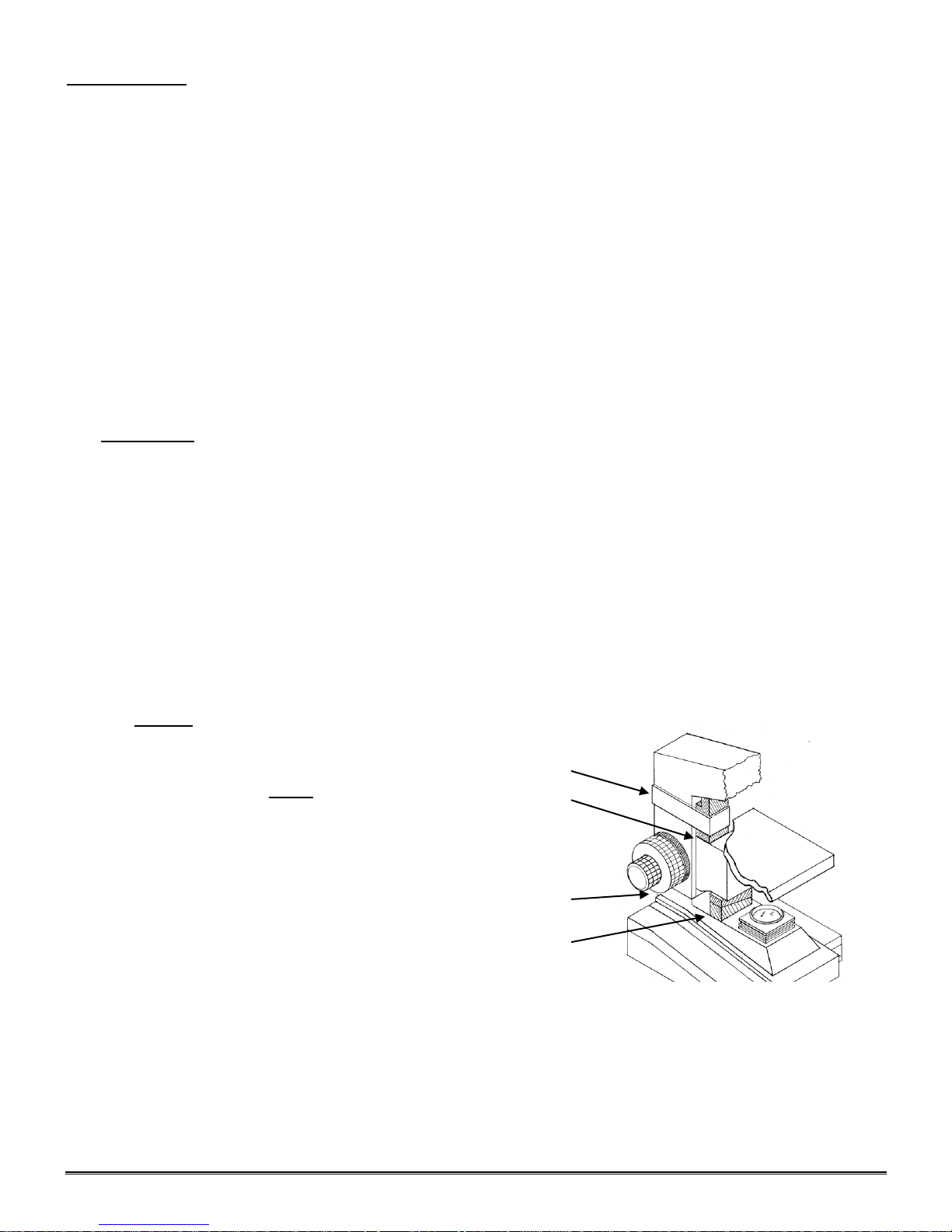
A. Lay container (A) flat and carefully remove microscope head and stand.
NOTICE To protect focus mechanism during
shipment, two black plastic wedges (b)
and one black plastic block (c) are
inserted at strategic points as indicated.
These plastic parts MUST be removed prior
to operating microscope. Failure to do so
will result in damage to focusing mechanism
and will void your warranty.
1. Remove two black Velcro straps (a).
2. Remove wedges (b) by pulling apart the
two parts of wedge in opposite directions.
3. Lower stage by rotating coarse focus
knob, on side of microscope illustrated,
in counter-clockwise direction
4. Remove blocks (c) from stand.
5. These components should be retained with styrofoam container
B. Carefully remove from the stand all tape and packing material used to protect microscope components during
shipment.
C. Un-wrap the components, making certain that lens surfaces do not come in contact with dust, dirt,
fingerprints. Damage to optical surfaces can result from such contaminants, and reduce image quality.
4
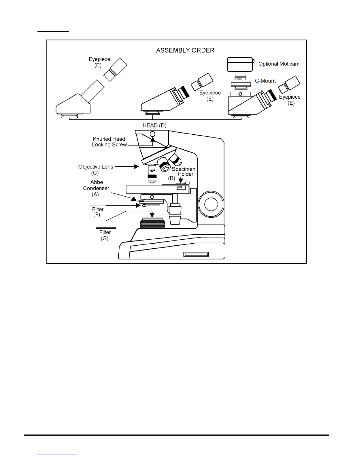
ASSEMBLY
A. Abbe Condenser: Pre-mounted in unit.
B. Specimen holder: Pre-mounted on stage.
C. Objectives: Unless otherwise note, they are pre-mounted on the microscope.
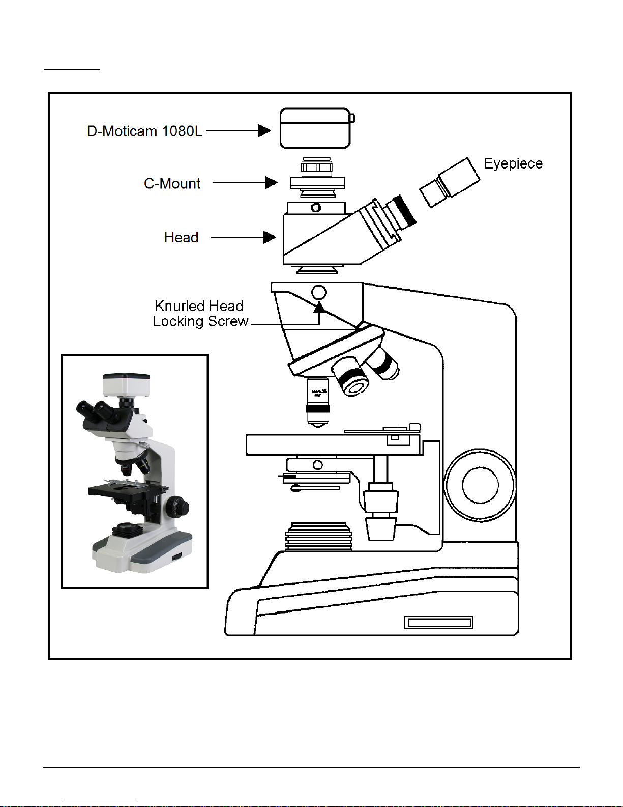
D. Heads: On all series, the head comes pre-mounted to the body of the microscope. Position head so that it
faces either forward or backward, whichever suits your preference or needs, and tighten knurled head locking
screw.
1. Dual viewing teaching head - Mounting vertical eyepiece tube with diopter to head: Loosen knurled
locking screw, remove black dust cap from vertical port. Insert vertical eyepiece tube with diopter into
vertical port. Retighten knurled screw to secure vertical eyepiece tube in place.
2. Trinocular head - Mounting C-Mount to head: Loosen knurled locking screw, remove black dust cap
from vertical port. Insert C-Mount and retighten knurled screw to secure in place.
a. Trinocular head provided with a three position sliding rod to direct light through microscope. The
three position sliding rod (b) allows user to easily direct microscope image into desired path.
1) Rod pushed completely into head; 100% of microscope image is directed to binocular
eyepieces.
2) Rod at mid-position (pull or push rod until you feel a gentle click stop), 100% of microscope
image is directed to trinocular port.
3) Rod pulled to fully extended position; 30% of image directed to binocular eyepieces, 70%
directed to trinocular port.
5
E. Eyepieces: Remove the dust caps from eyepiece tubes. Avoid touching any lens surface and Insert
eyepieces into the eyepiece tubes.
F. Filter: Swing out filter holder has built in frosted filter – must be in place when using the 4x and 10x
objectives.
OPERATION
G. Illumination.
1. Before operating microscope, adjust intensity control located on side of base to the minimum
H. Interpupillary adjustment of viewing head (Models 168 and 169 only)
I. Focusing the microscope.
position. This should be done prior to each time light is turned on or off. This will extend bulb life.
2. Insert power plug into 12VDC switching power converter, then insert plug on other end of converter into
power jack on back of microscope base. Note that the 12VDC converter will operate on either 120v or
240v current, 50 hertz or 60 hertz, eliminating the need for any other transformer.
3. Push rocker switch at rear of base to ON position.
4. Rotate intensity dial on illuminator base until image is illuminated.
5. Adjust intensity of light to match requirements of objective and specimen slide.
6. In case of equipment malfunction, see “Trouble Shooting” procedures.
1. Look through microscope and adjust distance between the two eyepiece tubes by grasping the sliding
mounts to left and right of eyepieces and sliding together or apart.
2. When a full field of view is observed through both tubes, and images blend into one, interpupillary
distance is corrected for your eyes. Check the interpupillary scale and note index reading for future
reference, in case other users will be changing this adjustment from time to time.
3. Adjust the diopter scales, located on each eyepiece tube, to the same numerical value as indicated on
the interpupillary scale. This must be done in order to maintain parfocality of objective lenses. If
interpupillary distance is changed, adjust eyepiece diopters accordingly.
1. Position the 4x objective lens into the optical path, making sure that lens is properly indexed in its clickstop position.
2. Place standard specimen slide (cover slip up) on top of stage surface.Swing moveable finger on slide
holder outward. Place specimen slide against fixed side of slide holder. Slowly release moveable finger
until it makes contact with specimen slide.
3. Rotate coarse focusing controls until specimen comes into focus.
6
4. Adjust fine focus controls until specimen is in sharp focus.
Objective Specification Chart
Objective
N.A.
Color Code Ring
Field of View
Magnification
Din 4X
0.10
Red
4.5mm
40X
Din 10X
0.25
Yellow
1.8mm
100X
Din 40X
0.65
Blue
0.45mm
400X
Din 100X
1.25
White
0.18mm
1000X
5. Adjust diopter for difference in eyesight.
a. Using right eye, peer into the right eyepiece tube. Adjust sharpness of image by utilizing fine focus
controls.
b. Using left eye, peer into the left eyepiece tube. Adjust sharpness of image by turning diopter
adjustment located on left eyepiece tube.
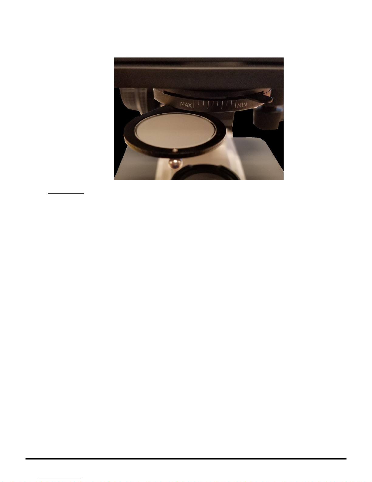
6. Adjusting the aperture (opening) of iris diaphragm.
Iris diaphragm should not be used to control the brightness of illumination, use light intensity control
knob to adjust light level. Iris diaphragms are designed to help achieve high resolution of specimen and
provide contrast in the image. Smaller apertures will deliver higher contrast to image. However, closing
aperture too much will reduce resolution. Experimentation is the best method of determining the correct
opening of diaphragm. Some suggested openings for iris diaphragm are:
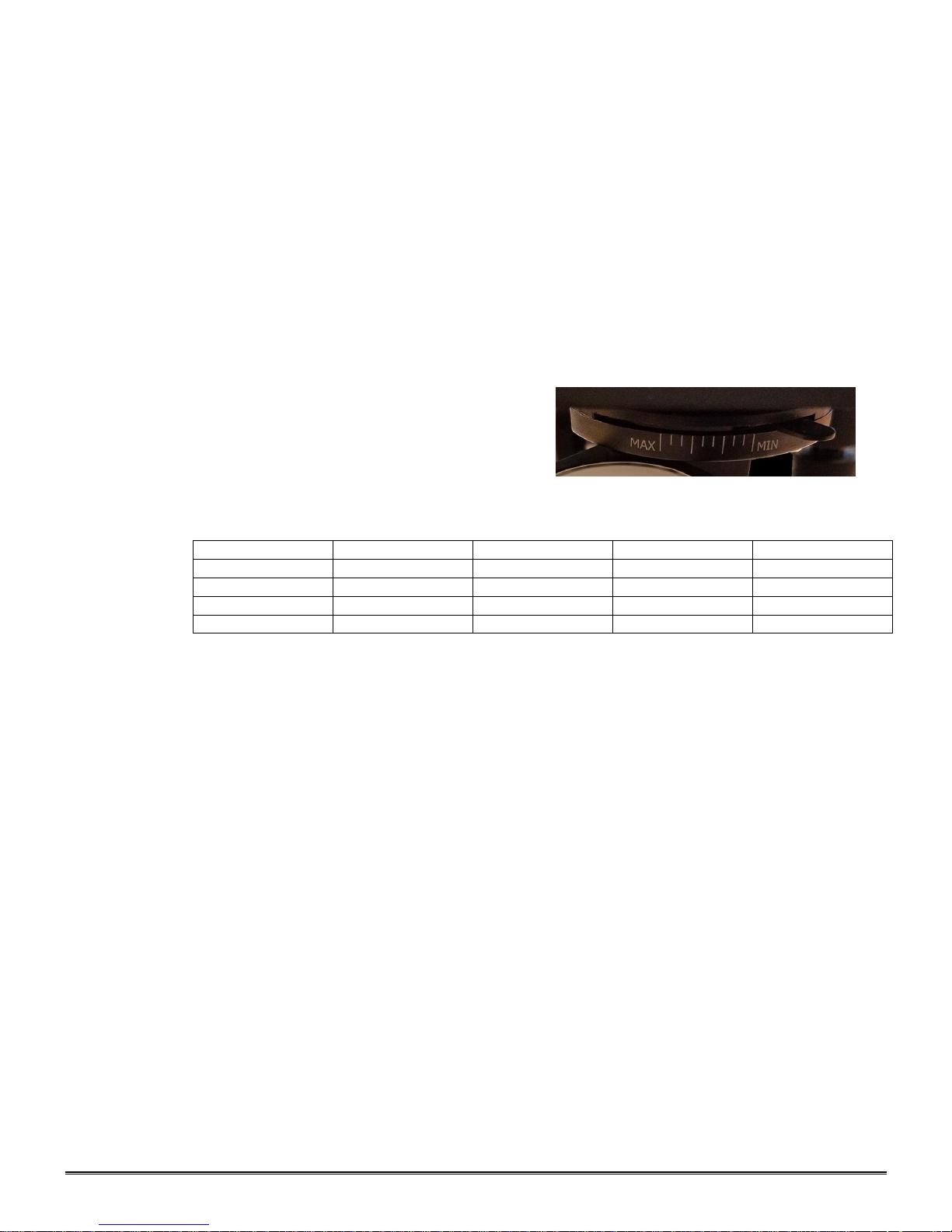
OBJECTIVE DIAPHRAGM OPENING
4x 1/8 open (MIN)
10x 1/8 to 1/4 open
40x 1/4 to 1/2 open
100x 1/2 to 3/4 open (MAX)
7. Changing magnification.
a. Rotate revolving nosepiece to position 10x objective into optical path.
b. This microscope has been parfocalized, which allows changes from one objective to another while
requiring only a slight adjustment of the fine focus controls.
c. When changing to the 40x and 100x objective lens, care must be exercised in order to prevent
damaging the front lens element and specimen slide.
d. In order to obtain maximum resolution of the 100x oil immersion lens, it is necessary to apply
immersion oil between the coverglass of slide and front lens of the objective.
1) Use of a very small amount of immersion oil is required. Only the very tip of the lens
should ever come in contact with the immersion oil. Oil should not come in contact
with the white sealant ring on the objective. Excess use of immersion oil will ruin your
objective and void your warranty.
2) All air bubbles must be removed from between lens and slide by rotating nosepiece back and
forth.
8. When finished viewing, all parts that come in contact with oil must be cleaned. Failure to do so could
permanently damage the 100x oil immersion objective lens. Use of Windex to clean immersion oil off
lens surfaces is recommended.
9. Coarse focus tension adjustment.
a. Tension adjustment knob is located between stand and coarse focus knob of microscope, on the
right side.
b. To tighten tension of coarse focus knobs, turn control in a counter-clockwise direction. It is
advisable to leave controls as loose as possible, tightening only enough to keep stage from drifting
down and out of focus. To loosen tension, turn control in clockwise direction.
7
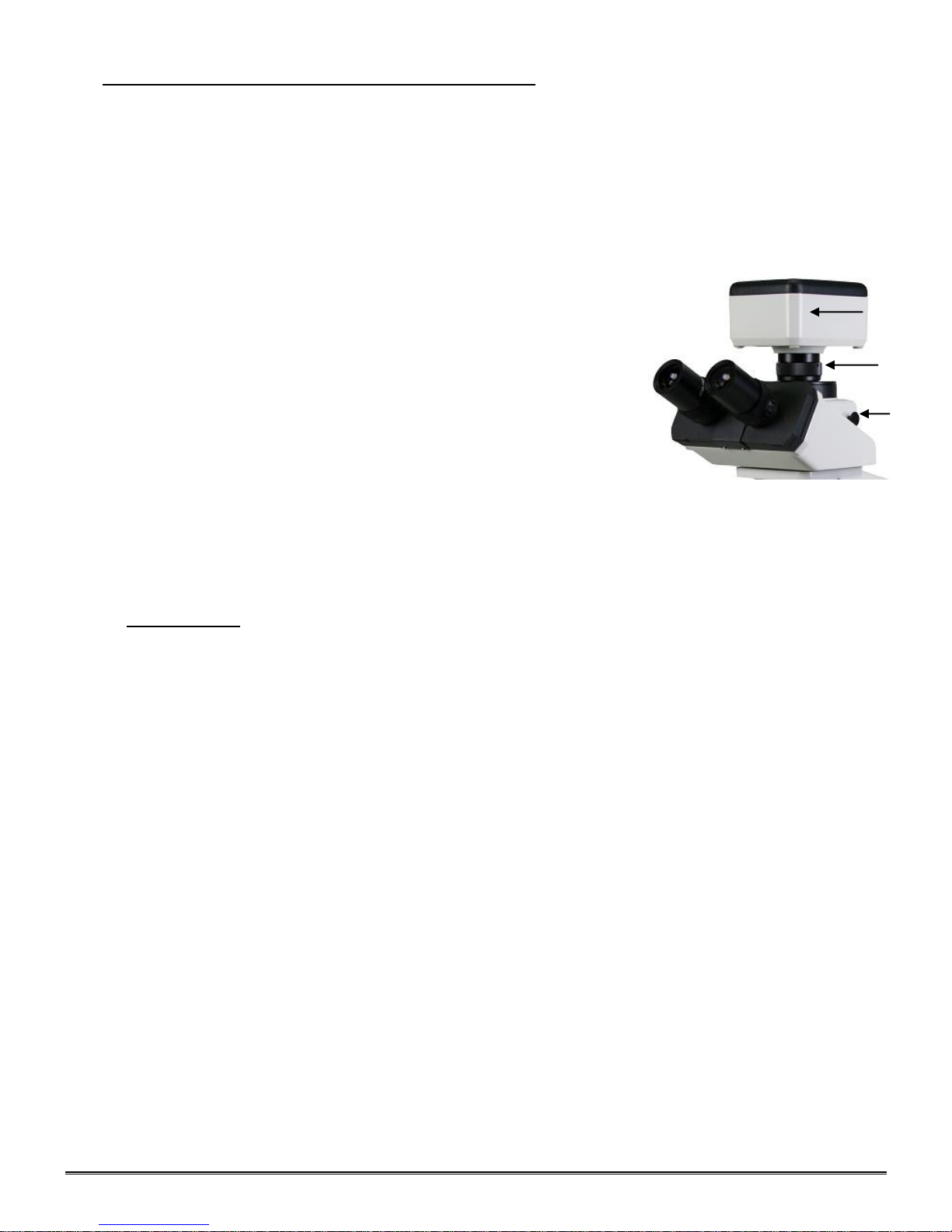
INSTALLING C-MOUNT CAMERA (to trinocular model only)
(b)
(c)
(a)
Trinocular model #169 is equipped with a port on top of head. Using the included C-Mount adapter and the
three-position sliding rod (c) allows use to easily direct microscope image into desired path.
1) Rod pushed completely into head; 100% of microscope image is directed to binocular eyepieces.
2) Rod at mid-position (pull or push rod until you feel a gentle click stop); 100% of microscope images is directed
to trinocular port.
3) Rod pulled to fully extended position; 30% of image is directed to binocular eyepieces, 70% directed to
trinocular port.
4) Remove front cap from the D-Moticam c-mount camera. Thread front of
camera onto threads of video adaptor (b).
Locate knurled screw located on side of trinocular port on microscope.
Turn screw counter-clockwise to permit removal of black plastic disk
covering trinocular port.
Insert video adaptor tube into trinocular port. If adaptor does not insert
easily, further loosen knurled screw at side of port until adaptor tube drops
into port and is firmly seated. Retighten knurled screw to secure adaptor
and camera in place. Pull sliding rod (c) until half way extended, to direct
100% microscope image to trinocular port. Proceed with operation of
digital camera and computer/monitor according to manufacturer’s
directions. With the live image on the monitor, slowly rotate the knurled
diopter on “C” adapter until image is in focus on monitor. If microscope
image does not remain in focus when microscope magnification is
changed, recheck digital c-mount camera chip size. Perhaps it will be
necessary to either replace or remove the top “CS” adaptor ring in order for
the video adaptor to be compatible with the chip size of your digital c-mount
camera.
MAINTENANCE
WARNING: FOR YOUR SAFETY, TURN SWITCH OFF AND REMOVE PLUG FROM POWER SOURCE
OUTLET BEFORE MAINTAINING YOUR MICROSCOPE. TO AVOID SHOCK OR FIRE HAZARD, IF
POWER CORD IS WORN, CUT OR DAMAGED IN ANY WAY, HAVE IT REPLACED AT ONCE.
A. OPTICAL MAINTENANCE
1. Do not attempt to disassemble any lens component. Consult an expert technical service company when
repairs not covered by these instructions are required.
2. Prior to cleaning any lens surface, brush dust or dirt off lens surfaces using a camel hair brush. Or use
air to blow dust and lint off surfaces. Use of compressed air in a can, available at any computer supply
store, is a good source of clean air.
3. Cleaning eyepiece lenses. Do not remove eyepiece from eyepiece tube. Clean only the outer surface.
Breathe on lens to dampen surface, then wipe with lens paper. Do not wipe lens surface while dry as
lenses are scratched very easily. Wipe a circular motion from center to outer edges.
4. Cleaning objective lenses. Do not remove objective lenses from microscope. Clean front lens element
only. Using a cotton swab saturated with distilled water, clean front lens surface. Inspect the lens using
a magnifying glass to insure that the element is clean. If immersion oil or specimen material of any kind
is evident, use a cotton swab dipped in a small amount of Windex to clean all foreign material from
objective lens surface. Such material will reduce, or totally block, image quality.
5. Cleaning condenser lens. Clean only the top lens surface, visible when looking through hole in top of
stage. Use same procedure as used for eyepiece or objective lenses.
6. Illuminator condenser lens. Use same procedure as used for eyepiece or objective lenses.
8
B. ELECTRICAL MAINTENANCE
WARNING: FOR YOUR SAFETY, TURN SWITCH OFF AND REMOVE PLUG FROM POWER SOURCE
OUTLET BEFORE MAINTAINING YOUR MICROSCOPE.
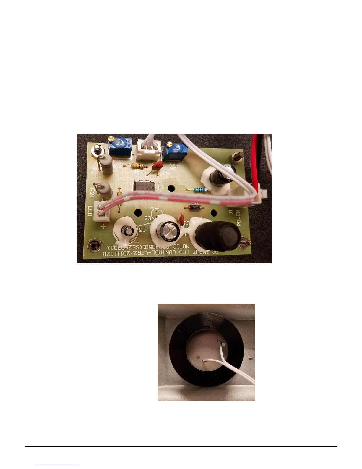
1. Replacement of lamp.
a. Carefully lay instrument on its side, taking care to avoid damage to the specimen slide holder
located on top of mechanical stage.
b. Remove 5ea cross head screws, holding base plate.
c. Carefully lay the base plate flat on the table.
d. Disconnect the LED cable from the plug socket on the LED circuit card.
e. Your microscope requires a 3W LED bulb assembly – Part # 800-500
f. The LED bulb is located within the lamp housing. It is held in place with screw on holder. Simply
unscrew the ring holder to remove the bulb assembly.
g. Assemble the unit in the reverse order.

9
Introduction to the DC20-169 Series Microscope
D-Moticam 1080L
Sensor Type CMOS
Sensor Size 1/2.8"
Resolution 2 MP
Capture format (on SD-card) Still Image 1980 X 1080 / Video HD 1980 X 1080
Live Display Mode (through USB) 1980 x 1080
Live Display Mode (through HDMI) 1920 x 1080 (HD) @ 60 fps*
Pixel Size 2.8μm x 2.8μm
Data Transfer HDMI (1080P) and USB2.0
Operating Temperature From-10 to +60 Degrees Celsius non condensing
Slot SD Card (max 32 GB)
Supported OS Microsoft Windows XP/Vista/7/8 and MAC OSX
Minimum Computer Requirements 2GHz dualcore – RAM mem 2GB – Video mem min. 512 MB
10
ASSEMBLY
DC20-169 Series
11
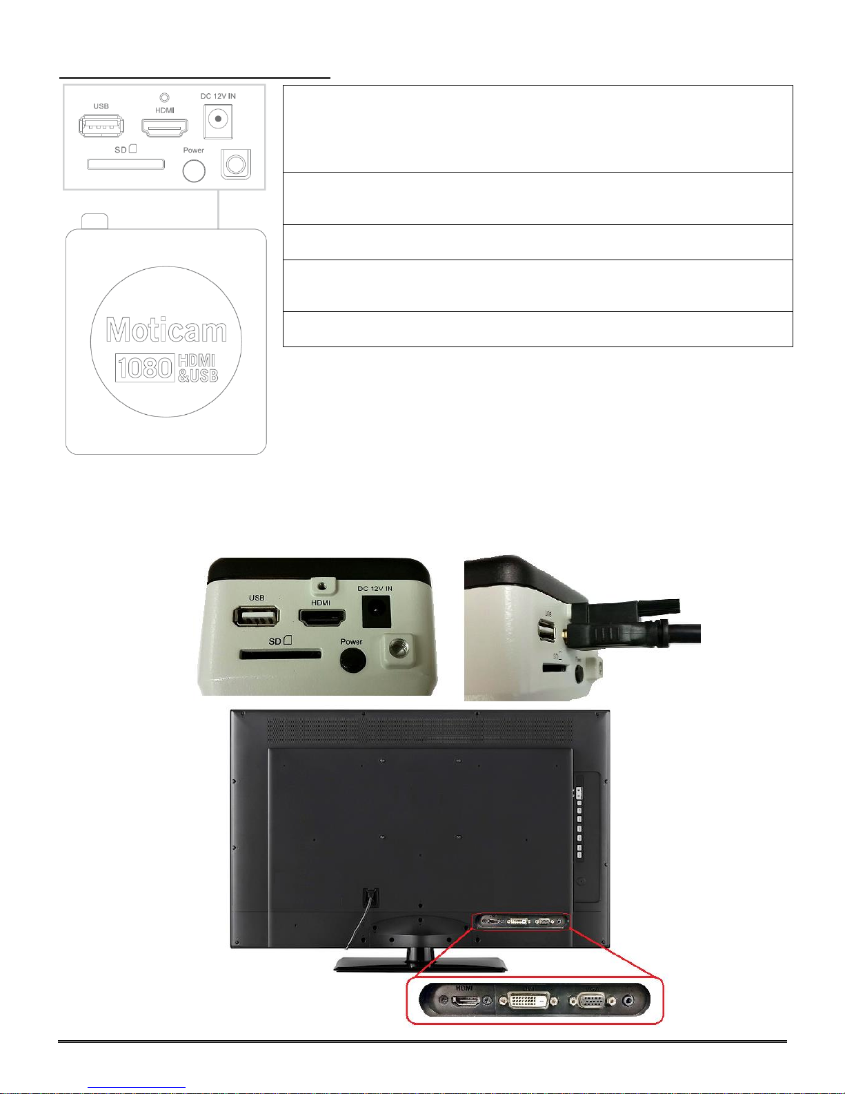
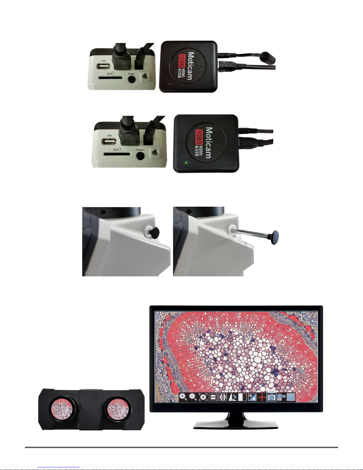
CAMERA CONTROLS AND PORTS
This USB port can also be used to connect a USB mouse so that the
camera can be controlled without a computer. The USB connection can
be used to connect the Moticam 1080 directly to a computer (not
recommended) to be used with the provided Motic Images Plus software.
HDMI port for connecting to an HDMI ready display (the cable is provided
in the Moticam 1080 box).
DC 12V Power port for connecting the included Power Supply.
SD Card slot for capturing images and video files onto an SD card. The
maximum size compatible is 32GB
Pressing this button will turn the camera on and off.
CONNNECTING CAMERA TO HD READY DEVICE
1. Connect the HDMI Cable, included with your camera, to the back of the D-Moticam 1080. Connect one end of
the HDMI cable (end with screw) to the 1080 and then connect the other end of the HDMI cable to the back of
your HD Ready device (Monitor, Projector, HDTV, etc..).
12
2. Plug the power cord into the back of the D-Moticam 1080.
3. Then press the power button one time to turn on the camera. The green power indicator should now illuminate.
4. Now make sure your microscope is on and you are focused in on your slide / specimen.
5. On the right hand side of the head, just behind the right eyepiece, is the three position slide bar. The slide bar
must be pulled out until it stops.
6. In this position, the slide should be visible through the eyepieces and displayed on your HD ready device.
 Loading...