

National Crank Assembly Instructions Manual
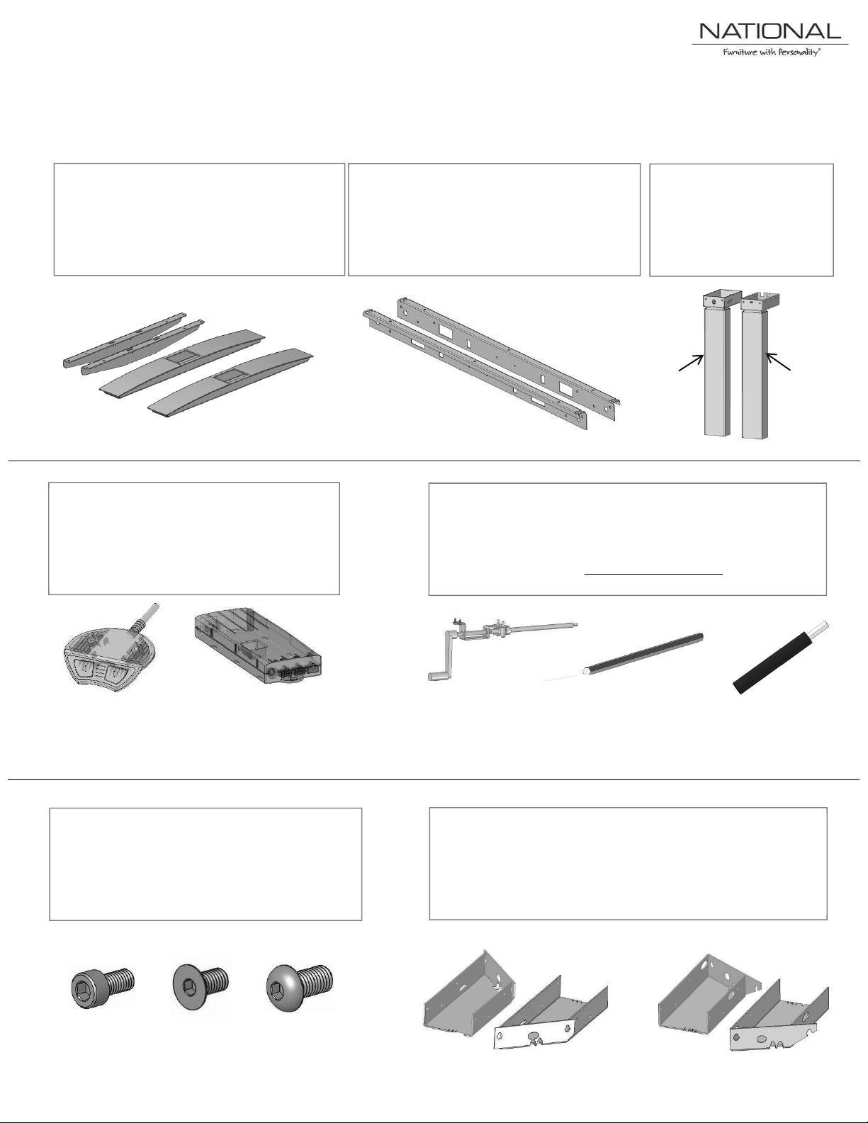
Parts Included
Foot Kit:
J-Rail Kit:
Column Kit:
Electrical Components:
A
B
Crank Components:
C D E*
Crank
Electric
3 Leg Table Components:
Hardware Pack:
F G H
I J K
L
· 2 Feet
· 2 Top Supports
· (A) Control Switch
· (B) Control Box
· Plug Set
· 2 J-Rails
· Hex Rod to be Included on a Crank
Assembly only.
· 2 Electric or Crank
Columns
· 3rd Leg option for 3 leg
Assembly
· (C) Crank Handle Assembly
· (D) Hex Rod
· (E) 3 Extension For 30 Deep Top Only*
· (F) M6x12mm Socket Head - QTY: 12 or 18
· (G) M6x12mm Flat Head - QTY: 4
· (H) M10x20mm Button Head - QTY: 4
EXTERNALLY MANAGED DOCUMENT, KIMBALL DOCUMENT NUMBER 2497634,-
· (I) LH 90 Degree Adapter (J) RH 90 Degree Adapter
· (K) LH 120 Degree Adapter (L) RH 120 Degree Adapter
· Need a 3rd Column to match Crank or Electric and 18 total Qty.
of screw (F).
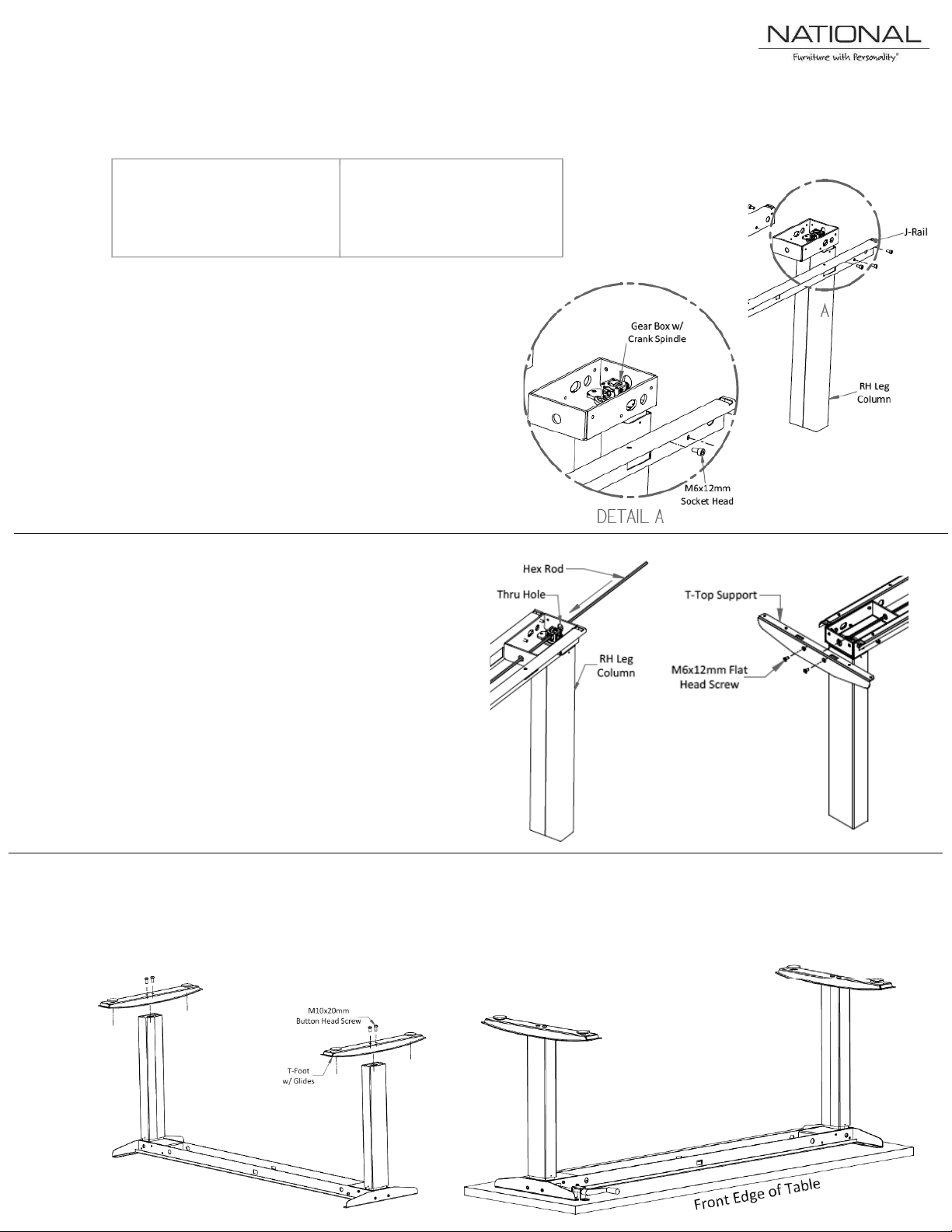
Crank Assembly Instructions
Crank Handle Assembly is
1. Line up J-Rails to the appropriate Column and
Fig. 1
Fig. 4
Fig. 2
2. Insert Hex Rod into the Thru Hole on either
4. Carefully flip the table as show in Fig. 4 and
REQUIRED TOOLS:
EACH TABLE INCLUDES:
Foot Kit w/ Top Supports
Fig. 3
5. To attach the table top to the assembly;
Fig. 5
· #2 Phillips Driver
· Metric Allen Wrenches
· Column Kit
· J-Rail Kit w/ Hex Rod
·
attach using the M6x12mm Socket head screws
provided.
- Note: The Leg Columns are marked
right and left handed inside the Gear
Box Case. Right hand is marked with a
blue circle and left hand is marked with
a black circle.
Leg Column (Fig. 2) and slide it through into
the other leg. Center the Hex Rod in the
assembly.
3. After the Hex Rod is in place, attach the top
supports to the appropriate columns with
the M6x12mm Flat Head Screws. (Fig. 3)
then attach the T-Feet using the M10x20mm
Button Head Screws provided.
place the top supports an appropriate distance
from the front of the table top and then center
onto the table top.
supposed to line up flush to
the front edge of the table
when compressed.
 Loading...