

National Confide Chair Ganging Assembly Instruction Manual
Assembly Instruction
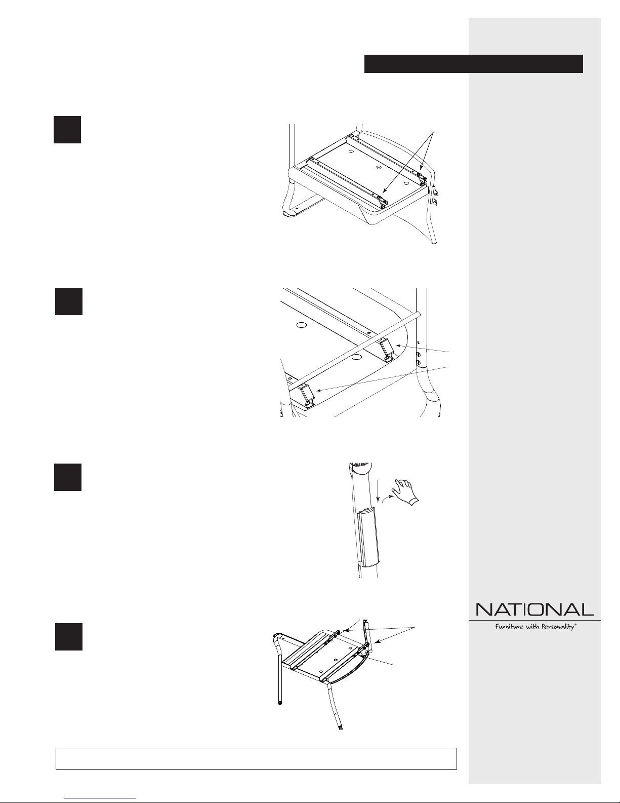
Remove the screws holding the connection
bars using a #3 phillips head screwdriver
1
(Figure A).
Note: Keep the screws and connection bars
for later use.
Determine which side of existing chair
for add-on chair. Remove the inserted
2
caps from the under-seat beam on the
determined side of existing chair.
NOTE: Under-seat beam caps are located
on the bottom side of the chair as shown
in Figure AA.
Remove the finger bracket cover from
the back of the add-on side of existing
3
chair. To disengage press down and out
on the top tab (Figure B).
Figure A
Figure AA
Figure B
Confide Chair Ganging
Screws
Recommended Tools
• #3 Phillips Head Screwdriver
Caps
Package Contents Qty.
• #1/4"-20 x 3/4" Truss Head
Screw 4 per bar
• #1/4"-20 x 1/2" Flat Head
Screw 2
• Connection Bar
2 per add-on side
Place the connection bars into the open
4
exposed beam ends of the add-on chair,
aligning mounting holes. Attach with
two (2) 1/4"-20 x 3/4" truss head
screws per connection (Figure C).
Proper product installation, in accordance with these instructions, is the responsibility of the installing agent. If you have any
questions concerning these instructions, please call National Customer Service 800.482.1717.
Figure C
Screws
Bars
Telephone 800.482.1717
Fax 812.482.8800
www.NationalOfficeFurniture.com
Part #2421495
Rev,A
Printed in U.S.A
© 2012 Kimball International, Inc.
Assembly Instruction
Confide Chair Ganging
5
6
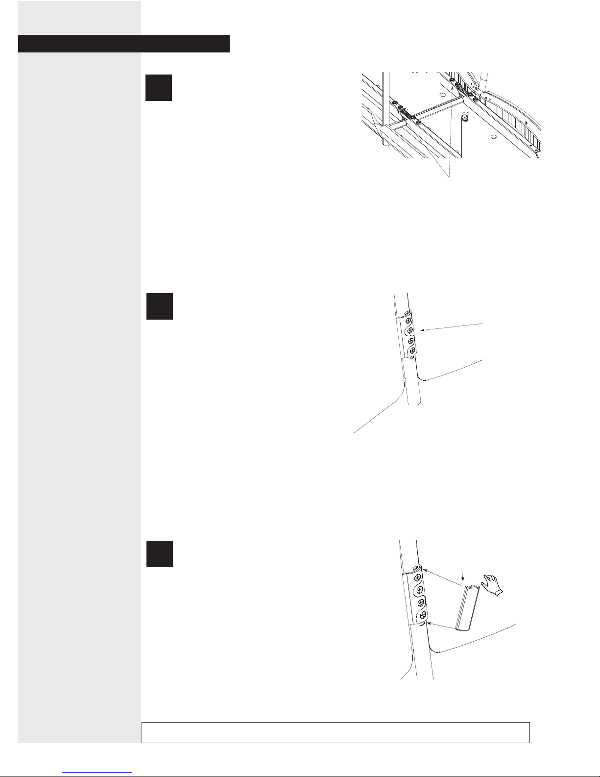
Attach the add-on chair to the existing
chair by placing the connection bars on
the add-on chair into the open exposed
beam ends of the existing chair, align
the mounting holes. Attach with two (2)
1/4"-20 x 3/4" truss head screws for
each connection bar.
NOTE: Figure D shows the bottom side
of the chairs, where the under-seat
beams and connection bars are located.
Align the finger bracket of the add-on
chair to the finger bracket of the existing
chair. Attach with two (2) 1/4"-20 x 1/2"
flat head screws (Figure E).
Figure D
Attach with two (2) 1/4-20 x
3/4" truss screws for each bar.
Figure E
Attach finger bracket
with (2) 1/4"-20 x 1/2"
flat head screws.
To attach the finger bracket cover,
7
Proper product installation, in accordance with these instructions, is the responsibility of the installing agent. If you have any
questions concerning these instructions, please call National Customer Service 800.482.1717.
align the bottom tab in the slot, press
down and in to engage the top tab
(Figure F).
Figure F
 Loading...