

National Alloy Assembly Instruction Manual
Proper product installation, in accordance with these instructions, is the responsibility of the installing agent.
If you have any questions concerning these instructions, please call National Customer Service 800.482.1717.
Assembly Instrucon
Telephone 800.482.1717
Fax 812.482.8800
www.NationalOfficeFurniture.com
Part # 2951091
Rev, A
Printed in U.S.A
© 2014 Kimball International, Inc.
Package Contents
Alloy
Fixed Height Double
Bases
Hardware Qty
M6 x 12 8
Handle 4
Lock Plate 4
Mounting Bracket 4
Woodscrews 8
Tools Required
4mm Allen Wrench
Screw Driver
#2 Phillips Bit
Note: This assembly instrucon will cover all conguraons of Alloy xed
height double bases.
1
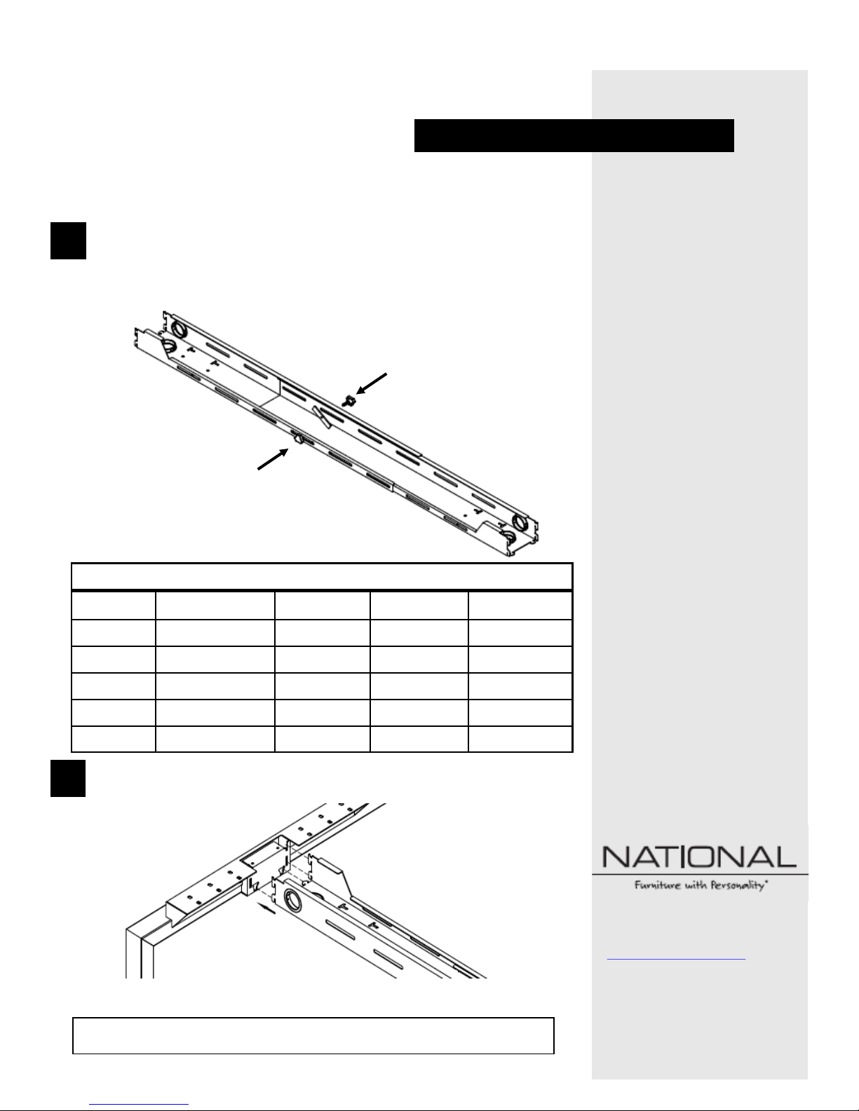
Assemble the two adjustable upper channels as shown in Figure A. Using
the supplied handle and lock plate roughly set the length of the adjustable
channel to the desired surface size and conguraon ordered in Figure B.
Repeat Step 1 for the second adjustable upper channel supplied.
Figure B:
Surface Size Freestanding: Start: Mid: End:
48 39 1/2” 42” 44 1/2” 42”
54 45 1/2” 48” 50 1/2” 48”
60 51 1/2” 54” 56 1/2” 54”
66 57 1/2” 60” 62 1/2” 60”
72 63 1/2” 66” 68 1/2” 66”
Figure A:
2
Using the tabs as shown in Figure C, aach one side of the adjustable
upper channel to the rst end leg.
Figure C:
Proper product installation, in accordance with these instructions, is the responsibility of the installing agent.
If you have any questions concerning these instructions, please call National Customer Service 800.482.1717.
Assembly Instrucon
Telephone 800.482.1717
Fax 812.482.8800
www.NationalOfficeFurniture.com
Part # 2951091
Rev, A
Printed in U.S.A
© 2014 Kimball International, Inc.
Package Contents
Alloy
Fixed Height Double
Bases
Hardware Qty
M6 x 12 8
Handle 4
Lock Plate 4
Mounting Bracket 4
Woodscrews 8
Tools Required
4mm Allen Wrench
Screw Driver
#2 Phillips Bit
3
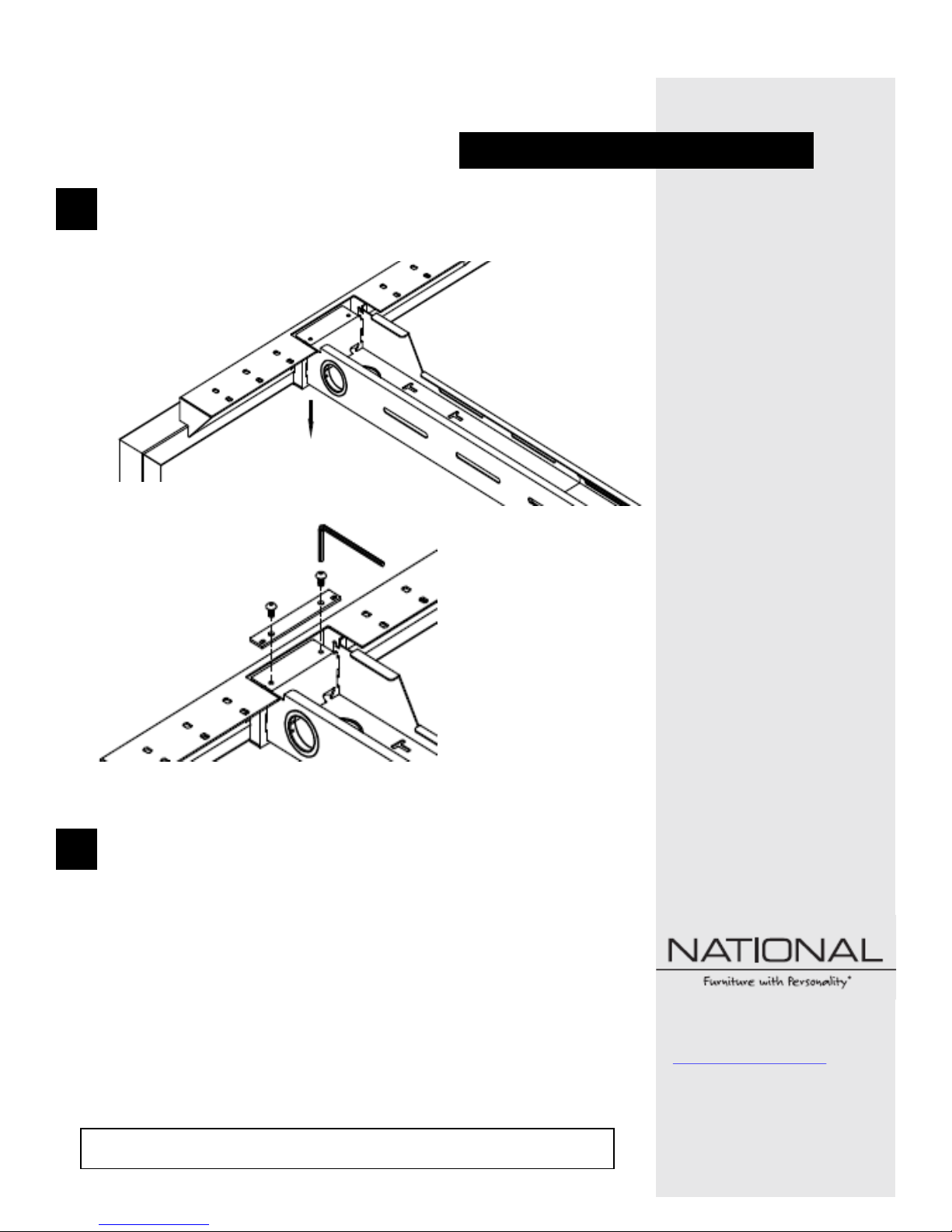
Verify the upper channel is fully seated as shown in Figure D. Using the
mounng bracket and M6 x 12 screws provided, secure the adjustable
upper channel to the end leg as shown in Figure E.
4
Repeat steps 2-3 for all remaining adjustable upper channels and connecon points. Once complete, the enre frame should be constructed to
your desired conguraon.
Figure D:
Figure E:
 Loading...