

National 5600 Instruction Manual

#5600 PANTHER
®
PROPANE POWERED
FLOOR PREP SYSTEM
INSTRUCTION
MANUAL
Read Manual Before Operating Machine
9250 XYLON AVENUE NORTH • MINNEAPOLIS, MN 55445 • U.S.A.
800-245-0267 • 763-535-8206 • FAX 763-535-8255 • FAX 800-648-7124
WEB SITE: www.nationalequipment.com • E-MAIL: info@nationalequipment.com
National
Flooring Equipment, Inc.

Page 2
TABLE OF CONTENTS
Table of Contents ....................................................................................................2-5
Hydraulic Safe Operation ........................................................................................6-7
A. Maintaining A Safe Work Environment ................................................................6
B. Pressure............................................................................................................6-7
C. Flammability ........................................................................................................7
D. Hydraulic Fluid......................................................................................................7
Rules for Safe Operation........................................................................................8-10
A. General Rules ..................................................................................................8-9
B. Characteristics of a Defensive Operator ............................................................10
Safety Instructions/ Precautions ..........................................................................11-12
Battery Safe Operation ..............................................................................................13
A. First Aid ..............................................................................................................13
B. Ventilation ..........................................................................................................13
Motor Safe Operation ................................................................................................14
Troubleshooting....................................................................................................15-16
Features/Specifications ........................................................................................17-18
A. Vibration/Sound Data ........................................................................................18
Operating Controls ..............................................................................................19-22
A. Start-Up Procedure ............................................................................................19
B. Throttle Control ..................................................................................................19
C. Hydraulic Levers ..........................................................................................19-20
D. Seat Switch ...................................................................................................... 20
E . Cylinder Lift ........................................................................................................20
F . Shut-Down Mode ..............................................................................................21
G. Machine Storage ..............................................................................................21
H . Changing Propane Tank ....................................................................................22
i. Carbon Monoxide Information and Warnings ............................................22
Operational Tips ........................................................................................................23
A. Caster ................................................................................................................23
B. Foot Peg ............................................................................................................23
C. Seat....................................................................................................................23
D. Disarm Machine ................................................................................................23
E. Turn Machine Off................................................................................................23
F. Leakage ............................................................................................................23
G. Angle of the Head is Set Steep ..........................................................................23
H. Raising or Lowering the Slide Plate ..................................................................23

Page 3
TABLE OF CONTENTS
Loading/Unloading ..............................................................................................24-25
A. Dock Heights....................................................................................................24
B. Power-Gate ......................................................................................................24
C. Ramps ..............................................................................................................24
D. Forklift Cups ....................................................................................................25
E. Winches ..........................................................................................................25
F. Transporting ....................................................................................................25
G. Wheel Chocks ..................................................................................................25
Center of Gravity ......................................................................................................26
Job Site Movement ..............................................................................................27-28
A. Taping Wheels..................................................................................................27
B. Leap Frogging Boards......................................................................................27
C. Palletizing ........................................................................................................27
D. Front Wheel Assembly ....................................................................................27
E. To Move Machine Without Power ....................................................................28
F. Moving Machine on Caster ..............................................................................28
Wheel Sizes ..............................................................................................................29
A. Wheel Size ......................................................................................................29
Cutting Heads and Blades....................................................................................30-32
A. Dialing in the Machine......................................................................................30
B. Saving Time with Extra Cutting Heads ............................................................30
C. Adjusting Slide Plate and Cutting Head ..........................................................30
D. Shear Point ......................................................................................................30
E. Weight vs. Sharpness ......................................................................................31
F. Cutting Head Angle ..........................................................................................31
G. Steep Cutting Head Angle................................................................................31
H. Swivel Head ....................................................................................................31
I. Cutting Head Insertion ....................................................................................31
J. Shank Blade Insertion ......................................................................................32
K. Blade Setting....................................................................................................32
L. Self-Scoring Blades..........................................................................................32
M. Blade Insertion or Blade Changing ..................................................................32
Blade Application/Set-Up ....................................................................................33-35
A. Ceramic Set-Up..................................................................................................33
B. Wood Set-Up......................................................................................................33
C. Secondary Backing Carpet Set-Up ....................................................................33
D. Foam Back Carpet Set-Up ................................................................................33

Page 4
TABLE OF CONTENTS
E. Double Stick Carpet Set-Up ..............................................................................33
F. VCT Tile Set-Up ................................................................................................33
G. Rubber Tile Set-Up ............................................................................................33
H. Re-Scraping Set-Up ..........................................................................................34
I. Thin Coating Set-Up ..........................................................................................34
J. Working Over Concrete......................................................................................34
K. Working Over Wood ..........................................................................................34
L. Working Over Soft Sub-Floor ............................................................................34
M. Cross Room Ditching ........................................................................................35
N. Checker Board Ditching ....................................................................................35
Blades ..................................................................................................................36-39
A. Types of Blades..................................................................................................36
B. Blade Sharpening ..............................................................................................37
C. Self-Scoring Blade Sharpening ..........................................................................37
D. Carbide Tipped Blade Sharpening ....................................................................37
E. Blade Selection Chart ..................................................................................38-39
Machine Maintenance ..........................................................................................40-46
A. Maintenance & Inspection List ..........................................................................40
B. Slide Plate ........................................................................................................41
C. Lower Cutting Head Support..............................................................................41
D. Leak Maintenance..............................................................................................41
E. Oil Level & Hydraulic Oil Change Out ................................................................42
F. Hydraulic Cylinder Change Out..........................................................................42
G. Engine Oil Change Out ......................................................................................43
H. Hose Change Out ..............................................................................................43
I. Foot Peg ............................................................................................................43
J. Pump Change Out ............................................................................................43
K. Valve Change Out ..............................................................................................43
L. Engine Change Out............................................................................................44
M. Wheel Motor Change Out ..................................................................................44
N. Wheel Changing ................................................................................................44
O. Changing Hydraulic Fluid Filter ........................................................................45
P. Changing Engine Air Filter ................................................................................45
Q. Caster Maintenance ..........................................................................................45
R. Engine Maintenance ..........................................................................................45
S. Switches ............................................................................................................46
T. Seat Replacement..............................................................................................46
U. Debris Deflector Mounting Instructions ..............................................................47

Page 5
TABLE OF CONTENTS
Complete Parts List ..............................................................................................48-52
Part Numbers and Diagrams ..............................................................................53-66
A. External Parts ..........................................................................................................53
B. External Parts ....................................................................................................54
C. Beeper & Hood Parts ........................................................................................55
D. Gear Pump Parts................................................................................................56
E. Wheel Parts........................................................................................................57
F. Control Lever Parts ..........................................................................................58
G. Single Spool & Hose Parts ................................................................................59
H. Double Spool & Hose Parts................................................................................60
I. Filter & Tank Parts ..............................................................................................61
J. Cylinder Parts.................................................................................................... 62
K. Slide Plate/Deflector, Caster & Foot Peg Parts ..................................................63
L. Propane Tank Parts............................................................................................64
M. Engine Battery....................................................................................................65
N. Battery/Weights ..................................................................................................66
Labels..................................................................................................................67-68
Accessories ..............................................................................................................69
Blades & Cutting Heads ......................................................................................70-71
Wiring Diagrams ......................................................................................................72
Material Safety Data............................................................................................73-78
Fire Extinguisher Material Safety Data................................................................79-85
Guarantee ................................................................................................................86
Return Sheet ............................................................................................................87
Blade Order Form ..............................................................................................88-89
Kawasaki Engine Manual ....................................................................................Insert

Page 6
MAINTAINING A SAFE WORK ENVIRONMENT
Establishing a safe working environment in and around your hydraulic equipment is just common sense.
The easiest and most effective way to avoid problems is to make sure associates understand their
equipment, know how to operate it safely and recognize the danger it represents if handled carelessly. A
few things you must be aware of include:
1. PRESSURE: Hydraulic fluid under pressure is dangerous and can cause serious injury.
2. FLAMMABILITY: When ignited, some hydraulic fluids can explode and/or cause fires.
3. MECHANICAL: Hydraulic fluid creates movement, which causes parts of your equipment to move or
rotate. Always be aware of what you are doing.
4. MOISTURE: Use caution when operating in wet or high moisture conditions. Make sure all electrical
fittings, switches, cords plus strain reliefs are in good condition. Always unplug when not in use and
when doing any service work.
5. ELECTRICAL: Faulty wiring can also be an electrical hazard. A regular preventive maintenance
program should always include a wiring check. Unplug batteries and/or charger before servicing.
6. TEMPERATURE: Because this machine operates at a relatively low pressure, overheating is not
common. If surface of tank becomes too hot to touch by hand (above 130º), shut off machine and
allow to cool off.
PRESSURE
Our system runs at or below 2,000 psi. Never look for a leak when unit is under pressure. Using your
hand could cause serious injury. A few common ways to encounter hydraulic fluid under pressure include:
1. PINHOLE: Fluid under pressure can cause serious injury. It can be almost invisible escaping from a
pinhole, and it can pierce the skin into the body. Do not touch a pressurized hydraulic hose
assembly with any part of your body. If fluid punctures the skin, even if no pain is felt, a serious
emergency exists. Obtain medical assistance immediately. Failure to do so can result in loss of the
injured part or death.
2. LEAK: Keep fittings and hoses tight. Only check and service when not under pressure. Leaking
hydraulic fluid is not only unsightly, it’s hazardous. In addition to making workplace floors slippery and
dangerous, leaks also contaminate the environment. Before cleaning an oil spill, always check EPA,
state and local regulations.
LEAK AT THREAD END/SEAT
Problem: Coupling leaks at thread or seat. This may be caused by any of the following:
a. Missing or damaged O -rings.
b. Damaged threads or seat angle.
c. Thread alignment.
d. Incompatible thread ends or seat angles.
e. Over or under torquing.
Solution: Remove the connection and inspect.
1. Certain couplings require the use of an O-ring. If it is missing, replace it. If an O-ring is used,
check for damage caused by installation or possible material breakdown from heat or fluid
incompatibility. Alternative O-ring materials may be required. Replace if necessary.
2. Check the threads and/or seat angle for damage that may have occurred prior to or during
installation. Any ding or burr may be a potential leak path. Replace if necessary.
HYDRAULIC SAFE OPERATION

Page 7
HYDRAULIC SAFE OPERATION
PRESSURE (continued)
3. If the coupling was misaligned during installation, threads may have been damaged. Replace
and carefully install.
4. Over torquing of a threaded connection can stretch and damage threads and mating seat
angles. Over torquing can also damage the staking area of the nut. Under torquing does not
allow proper sealing.
3. BURST: Whether due to improper selection or damage, a ruptured hose can cause injury. If it bursts,
a worker can be burned, cut, injected or may slip and fall.
4. COUPLING BLOW-OFF: If the assembly is not properly made or installed, the coupling could come
off and hit or spray a worker, possibly resulting in serious injury. Never operate machine without
guards.
FLAMMABILITY
With the exception of those comprised primarily of water, all hydraulic fluid is flammable when exposed to
the proper conditions (including many “fire-resistant” hydraulic fluids).
Leaking pressurized hydraulic fluids may develop a mist or fine spray that can flash or explode upon contact
with a cause of ignition. These explosions can be very severe and could result in serious injury or death.
Precautions should be taken to eliminate all ignition sources from contact with escaping fluids, sprays or
mists resulting from hydraulic failures. Sources of ignition could be electrical discharges (sparks), open
flames, extremely high temperatures, sparks caused by metal -to -metal contact, etc.
HYDRAULIC FLUID
Only use Texaco Rando 46 Hydraulic Oil or Compatible Fluid like IS032. Non-compatible fluids could
cause damage to unit or serious injury.
CAUTION: Never check for leaks over hose or hydraulic connections. Instead, use a piece of
cardboard to locate a pressurized leak. For drips (low pressure leaks), use a rag to clean the area and
determine where the leak originates.
CAUTION: Never touch a pressurized hose assembly. Shut down the hydraulic system before
checking hose temperature.
WARNING: When using electric tools, always follow basic safety precautions to reduce the risk of
electric shock and personal injury.

Page 8
RULES FOR SAFE OPERATION
READ AND SAVE ALL INSTRUCTIONS FOR FUTURE USE. Before use, be sure everyone
operating this equipment reads and understands this manual as well as any labels packaged with or
attached to the machine and components and view the instruction video. Extra copies of the manual and
video are available. In cases where personnel have an insufficient knowledge of the English language,
proper training must be obtained before using the 5600 machine.
1. KNOW YOUR EQUIPMENT: Read this manual and view instruction video carefully to learn
equipment applications and limitations as well as potential hazards associated with this type of
equipment.
2. DISARM MACHINE: Remove cutting head or drop cutting head to the floor when machine is not
in use.
3. DO NOT “SIDE HILL” MACHINE: See Page 24 & 26.
4 . AVOID DANGEROUS ENVIRONMENTS: Do not use in rain, damp or wet locations, or in the
presence of explosive atmospheres (gaseous fumes, dust or flammable materials). Remove materials
or debris that may be ignited by sparks.
5. KEEP WORK AREA CLEAN AND WELL LIT: Cluttered, dark work areas invite accidents.
6. DRESS PROPERLY: Do not wear loose clothing. These may be caught in moving parts. Keep hands
and gloves away from moving parts.
7. USE SAFETY EQUIPMENT: Everyone in the work area should wear safety goggles or glasses
complying with current safety standards. Wear hearing protection during extended use and a dust
mask for dusty operations. Hard hats, face shields, safety shoes, etc. should be worn when specified
or necessary.
8. KEEP BYSTANDERS AWAY: Children and bystanders should be kept at a safe distance from the
work area to avoid distracting the operator. Operator should be aware of who is around them and
their proximity.
9. PROTECT OTHERS IN THE WORK AREA: Provide barriers or shields as needed to protect others
from debris and machine operation.
10. USE PROPER ACCESSORIES: Using accessories that are not recommended may be hazardous.
Be sure accessories are properly installed and maintained. Do not delete a guard or other safety
device when installing an accessory, attachment or servicing.
11. CHECK FOR DAMAGED PARTS: Inspect guards and other parts before use. Check for
misalignment, binding of moving parts, improper mounting, broken parts and any other conditions that
may affect operation. If abnormal noise or vibration occurs, turn the tool off immediately and have the
problem corrected before further use. Do not use damaged equipment. Tag damaged machine “DO
NOT USE” until repaired. A guard or other damaged parts should be properly repaired or replaced.
For all repairs, insist on only identical National replacement parts.
12. REMOVE ALL ADJUSTING KEYS AND WRENCHES: Make a habit of checking the adjusting keys,
wrenches, etc. are removed from the tool before turning it on.
WARNING: Disarm machine when not in use. Remove Cutting Head or lower Cutting Head to the
floor. When exiting machine (getting off machine), remove lower Cutting Head to the floor. When
transporting machine around job site, remove Cutting Head. Failure to follow these instructions could
cause severe bodily injury.

Page 9
RULES FOR SAFE OPERATION
13. GUARD AGAINST ELECTRIC SHOCK: Prevent body contact with grounded surfaces such as pipes,
battery plug connection, radiators, ranges and refrigerators. When scoring or making cuts, always
check the work area for hidden wires or pipes to reduce shock hazards.
14. AVOID ACCIDENTAL STARTING: Be sure equipment is turned off before plugging it in. Do not use
if the power switch does not turn the machine on and off properly.
15. DO NOT FORCE EQUIPMENT: Equipment will perform best at the rate for which it was designed.
Excessive force only causes operator fatigue, increased wear and reduced control.
16. KEEP HANDS AND FEET AWAY FROM ALL CUTTING EDGES AND MOVING PARTS.
17. WEAR GLOVES WHEN CHANGING BLADES.
18. DO NOT OVERREACH. MAINTAIN CONTROL: Stay properly seated. Keep proper footing and
balance at all times. Maintain a firm grip.
19. STAY ALERT: Watch what you are doing, and use common sense. Do not use when you are tired,
distracted or under the influence of drugs, alcohol or any medication causing decreased control.
20. STARTING MACHINE: Insure hydraulic levers are “centered” before turning on ignition switch.
Throttle should be pushed all the way down.
21. SHUT-DOWN MODE: Machine must be in shut-down mode.
22. MAINTAIN EQUIPMENT CAREFULLY: Keep control levers dry, clean and free from oil and grease.
Keep cutting edges sharp and clean. Follow instructions for lubricating and changing accessories.
Periodically inspect battery, charger’s and all plug connections. Have damaged parts repaired or
replaced.
23. STORE IDLE EQUIPMENT: When not in use, store in a dry, secured place. Keep away
from children. Remove blade or keep blade lowered to the floor (disarm machine).
24. MAINTAIN LABELS AND NAME PLATES: These carry important information. If unreadable or
missing, contact National for a free replacement.
25. MACHINE IS HEAVY, DO NOT DROP: Counter weights are heavy. Take caution when removing
or reassembling. Take caution when moving or transporting.
26. COMMERCIAL APPLICATION: Machine is intended for commercial use only.
27. MACHINE IS EQUIPPED WITH A FIRE EXTINGUISHER: Be aware of its proximity and how to
properly use it.
28. PROPER VENTILATION: CARBON MONOXIDE IS A VERY TOXIC, COLORLESS AND
ODORLESS GAS. When engines operate in enclosed spaces, such as warehouses, buildings under
construction, or tunnels, carbon monoxide can accumulate quickly and reach concentrations that are
dangerous for humans. It causes headaches, dizziness, lethargy and death. CO is usually the major
concern whenever LPG engines are used indoors
WARNING: Exposure to dust may cause respiratory ailments. Use approved NIOSH or OSHA
respirators, safety glasses or face shields, gloves and protective clothing. Provide adequate ventilation
to eliminate dust, or to maintain dust level below the Threshold Limit Value for nuisance dust as
classified by OSHA.
WARNING: Ventilation is required in confined work environments.

Page 10
RULES FOR SAFE OPERATION
CHARACTERISTICS OF A DEFENSIVE OPERATOR
• Education
• Alert
• Skills
• Judgment
• Common Sense
• Recognizes the Hazards
• Understands the Defense
• Acts Correctly
A GOOD OPERATOR IS A “DEFENSIVE” OPERATOR
QUALITIES
Education: Learns about the machine and the environment.
Alert: Stays alert at all timesnever lets guard down.
Skills: Only performs duties he/she is qualified to do. Always tries to improve.
Judgment: Plays it safe. Doesn’t take chances.
Common Sense: Does the right thing without having to be told. Applies knowledge.
Recognizes the Hazards: Maintains alertness. Anticipates danger.
Understands the Defense: Knows that safety isn’t an accidentit’s a thinking person’s choice.
Acts Correctly: Does not cave in to pure pressure. Performs correctly when supervised or not.
USE CARBON MONOXIDE DETECTOR WHEN OPERATING MACHINE
Included with the 5600 are a 75007 Lapel CO Monitor and a 75008 Clip. It is recommended that the
operator and anyone in the working vicinity wear the detector. Failure to do so could cause bodily injury
and/or death. The use of detectors helps to verify if work area is safe from Carbon Monoxide poisoning.
The detector has an adhesive strip on the back for mounting or can be worn with the included clip. It can
detect as little as 100ppm (part per million) carbon monoxide gas at approximate relative humidity range
of 33 to 50%. If the humidity is very high it can detect concentrations as low as 20ppm. The presence of
CO will change the impregnated silica color change from red to red/brown and then to gray/black as the
concentration levels increase. Once the detector is exposed to fresh air, it will return back to red. Shelf
life in an unopened pack is approximately two to three years (expiration date is visible through unopened
package on the back). Once opened it should be replaced approximately every ninety days. Write date
opened in provided area on the front of the detector. Read further user directions on the back of the
detector.

Page 11
• Only qualified, trained personnel should operate this unit.
• Loose or damaged parts should be replaced immediately. Failure to do so could cause equipment
damage or serious injury.
• Switches and levers should be inspected. (Disconnect battery charger from wall outlet and machine
from batteries before repairs to prevent electrical shock). Do not use if defective. Power on/off switch
should return to off when lever is released.
• Power control box, motor and switches should be completely enclosed at all times with no
exposed wiring.
• Disconnect negative lead before servicing. Failure to do so can cause damage to electrical
system and/or electrical shock.
• Only use National components. Failure to do so could cause damage or serious injury.
• Always be aware of support personnel and their proximity when in operation. Block off work area.
• Support personnel should never stand next to machine, in front of or behind machine while machine is
running. Failure to do so could cause serious bodily injury or death.
• Manual should be kept with machine in supplied holder for access by operator at all times.
• Always wear eye protection when running machine.
• Never defeat switches or guards.
• Remove blade when machine is not in use and/or lower cutting head to floor. Failure to do so could
cause serious bodily injury.
• Wear gloves when changing blades. Always shut machine off when changing blades.
SAFETY INSTRUCTIONS/ PRECAUTIONS
WARNING: Know and understand before operation. Failure to do so could cause damage to
equipment or bodily injury.
Read and understand operators instruction manual and instructional video
before operating this equipment.
WARNING: Failure to follow any of the above instructions could cause damage to machine,
damage to property or serious bodily injury or death.
The 5600 Propane Ride-On should be inspected for damage and defects at least once during
every working shift. Starting and stopping procedures must be followed in accordance with the
Operating Instructions. Before starting the 5600 Propane Ride-On, be sure that no person is
likely to be endangered by the 5600 Propane Ride-On movement.
WARNING: DANGER-Engine exhaust gases contain poisonous carbon monoxide. Carbon
monoxide is odorless and colorless and can cause injury or death if inhaled. Do not use equipment
indoors without adequate ventilation. Refer to OSHA guidelines and regulations concerning maximum
levels of exposure to carbon monoxide gases and other hazards associated with using internal
combustion engines.

Page 12
SAFETY INSTRUCTIONS/ PRECAUTIONS
Read and understand operators instruction manual and instructional video
before operating this equipment.
The 5600 Propane Ride-On has been equipped with a safety switch under the seat, which requires the
operator to be seated before the 5600 can be operated. Do not attempt the start-up procedure with out
being seated on the machine.
WARNING: Bypassing this or any other safety device may cause property damage and/or bodily injury.
Before carrying out maintenance or repair work:
•Let the engine and the exhaust system, cool down;
•Remove all traces of oil, combustible fuel or cleaning fluids from the scraper, its connections
and fittings in particular;
•Do not use any aggressive cleaning products;
•Be sure that all cleaning rags are fiber free;
•Retighten all loose fittings found during maintenance and repair work.
GASES, DUST, STEAM, SMOKE
Do not weld, flame cut or perform grinding work on the 5600 Propane Ride-On without written
authorization from the manufacturer. The danger of fire or explosion exists when work of this nature is
done. Begin maintenance work only when the machine is in Shut Down Mode (turned off).
SAFETY PRECAUTIONS (OPERATOR/PERSONNEL TRAINING)
Operating and maintenance personnel must verify availability of appropriate fire protection equipment, be
properly trained in the use of the equipment and know how to contact the Fire Department or Emergency
Medical Service if needed.

Page 13
BATTERY SAFE OPERATION
CAUTION - PRECAUTIONS:
a) Contact with electrolytic acid can cause skin irritation and damage clothing. Wear a protective
apron, gloves and goggles when working with batteries. Have plenty of fresh water and soap
nearby in case battery acid contacts your skin, clothing, or eyes.
b) Remove personal metal items such as bracelets, rings, necklaces, and watches when working
with batteries. A battery can produce a short circuit current sufficient enough to weld metal
objects, causing severe burns.
c) Never smoke or allow a spark or flame in the vicinity of the batteries. Caution must be taken
to reduce the risk of dropping metal tools onto the battery. A spark or short circuit may result in
an explosion.
FIRST AID
Immediately flush eyes with cold, fresh water for a minimum of 10 minutes if electrolytic acid comes in
contact with eyes. Seek professional medical attention.
VENTILATION
Blocking louvers or air flow perforations of convection or fan cooled battery chargers and/or machine will
result in damage to the unit. When installing the unit leave space for air to flow freely through the intake
and discharge louvers and/or perforations.

Page 14
MOTOR SAFE OPERATION
CAUTION - PRECAUTIONS: Before servicing, allow engine to cool down. Failure to do so
could cause bodily injury.
CHECK FLUID LEVELS
Check oil & coolant levels before operating.
CHECK FOR LEAKS
Inspect propane gas line for leaks.

Page 15
TROUBLESHOOTING
Trouble Possible Cause Remedy
1. The scraper does not work
when the pump is generating
pressure
a. Severe blockage in wheel
drive motor hoses
b. Wheel drive motors defective
a. Check hoses for blockage
and replace hose if necessary
b. Call National Service
Center
2. The hoses are worn a. Hoses rubbing on components
b. Hose has been exposed to
poor environmental conditions
a. Replace and protect the
hose
b. Replace hose and protect
equipment from poor
conditions
3. The machine makes an
unusually loud hissing or
whistling noise
a. Fluid is passing over relief
valves
b. Air in hydraulic circuit
a. If noise is continuous, call
a National Service Center
b. See Trouble 7 and 9
4. Oil deposits are evident on the
inner sides of the driving wheels
a. The shaft seals of the wheel
motors worn out
b. Hose fittings are loose
a. Have the shaft seals
replaced by a specialist
b. Tighten hose fitting.
Replace hose or fitting if
necessary
5. The machine has no power
with the engine running
at 3500 rpm.
a. Check valve adjustment
b. Check hoses for leaks
a & b. Contact National
Service Center immediately
Do not operate in this
condition!!
6. The scraper does not react
when the motion control joystick
is actuated
See possible cause 5a and 5b See remedy 5a and 5b
7. The hydraulic oil is very
cloudy. Excessive air in the
circuit can cause severe
damage to pump. Stop
machine and repair
immediately!
a. Water has entered
hydraulic tank
b. Oil is contaminated with dirt
c. Air has entered the circuit
a. Repair tank if necessary.
Drain and clean tank
thoroughly. Change oil.
b. Drain and clean tank
thoroughly. Change oil.
c. Contact National
Service Center

Page 16
TROUBLESHOOTING
Trouble Possible Cause Remedy
8. Excessive amount of oil
on chassis
a. Outside oil spilled on
chassis
b. Loose hose connections
c. Loose tank fittings
a. Clean machine thoroughly
and see if oil returns
b. Check for loose hoses
c. Check for loose fittings
9. Hydraulic oil and/or oil foam
leaking from oil tank. Excessive
air in the circuit can cause
severe damage to piston pumps.
Stop machine and repair
immediately!
a. Oil level too high
b. Oil level too low
c. Vent in return filter blocked
d. Air getting into hydraulic
circuit
a. Drain tank to correct level
b. Fill tank to correct level
c. Check for blockage
d. Check all suction lines.
Tighten all hose connections
and fittings
10. Engine dies or cuts out a. Fuel tank is empty
b. Oil is low
c. Operator not seated properly
a. Change or fill fuel tank
b. Fill oil to proper level
c. Position on seat correctly
11. Red ignition light stays on a. Oil is Low
b. Machine is overheating
a. Fill engine oil to proper level
b. Let engine cool. Add coolant
to proper level
12. Machine doesn’t start a. Machine needs to be primed a.Press primer button once &
restart machine
WARNING: DO NOT work with machine at idle. Doing so will cause damage to machine!

Page 17
FEATURES/SPECIFICATIONS
SPECIFICATIONS #5600
Width: 24½''
Height with Seat: 46"
Length without Jaw: 52''
Weight (machine only): 1116 lbs.
Added Weight:
Pocket Weight: 464 lbs.
Rear Weight: 83 lbs.
Gross Weight: 1663
Speed: Up to 150 feet
per minute
MOTOR INFORMATION (#5600)
RPM: 2950
Volts: 12 Volt System
HP: 20
Amps-Full Load: NA
Continuous Duty NA
Trailer Hitch
WARNING: Trailer hitch is only intended
to move small trailers on the job site.
Fuel Tank
Control Lever
Forward/Reverse
Neutral Break
Removable
Swivel
Cutting Head
Front Swivel
Caster
Adjustable
Foot Rest
(both sides)
Fork Lift
Cups
(both sides)
Extra weight
compartment
(both sides)
Lower Cutting
Head Support
#5600
Adjustable
Slide Plate
Cutting Head
Cylinder Lift
Fire Extinguisher

Page 18
FEATURES/SPECIFICATIONS
VIBRATION/SOUND DATA
VIBRATION DATA:
Axis
X
Y
Z
Vector
Sum
Stationary
>0.1
0.3
0.4
>0.1
Moving
0.5
0.3
0.1
0.6
Whole Body
Vibration Levels in m/s^2
Axis
X
Y
Z
Vector Sum
Left
0.5
0.3
0.6
0.9
Right
1.4
1.4
0.5
2.0
Hand/Arm
Vibration Levels in m/s^2
Stationary
Moving
dBA
77.0
73.0
Operator Sound Level
dBA ref. 20 Pa
SOUND DATA:
Emissions meets OSHA stantdards
Page 19
OPERATING CONTROLS
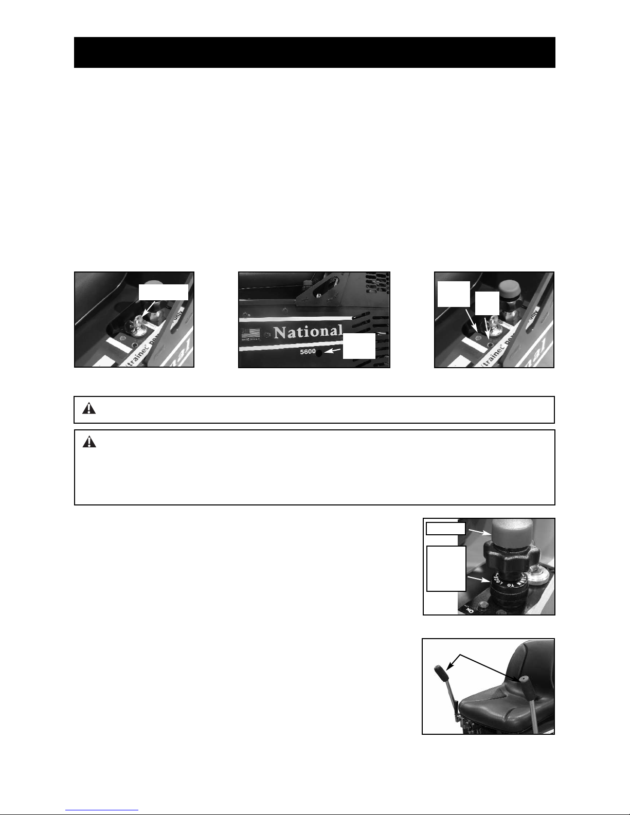
START UP PROCEDURE
POWER /Key Start (Figure A)
1. Open propane tank valve by turning knob CCW until fully open.
2. Operator must be seated in seat. The machine will not start unless the operator is seated.
3. Insure that hydraulic levers are “centered”.
4. Set throttle at a quarter open.
5. Start with ignition switch.
6. If machine does not start, press primer button once (in hole on side of machine) (Figure B)
7. Start with ignition switch again.
8. Both a Red & Green light will illuminate (Figure C). As soon as engine starts, the red light
will shut off. If the Red light does not shut off, turn machine off.
9. Adjust throttle to move to desired RPM.
Figure A
Figure D
KEY START
THROTTLE
Figure B
PRIMER
BUTTON
Figure E
Hydraulic Levers
WARNING: Ventilation is required in confined work environments. CARBON MONOXIDE IS
A VERY TOXIC, COLORLESS AND ODORLESS GAS. When engines operate in enclosed spaces,
such as warehouses, buildings under construction, or tunnels, carbon monoxide can accumulate
quickly and reach concentrations that are dangerous for humans. It causes headaches, dizziness,
lethargy and death. CO is usually the major concern whenever LPG engines are used indoors
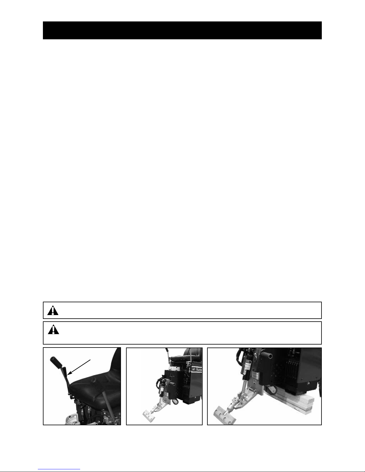
HYDRAULIC LEVERS (FIGURE E)
The hydraulic levers steer the machine. They are feathered spool
valves. For smooth even movement, always move levers slowly. Fast
movement on control levers will result in jerky, uneven movement.
(continued on next page)
THROTTLE CONTROL (FIGURE D)
• Make sure throttle is pushed down
• Start machine
• Adjust throttle to desired RPM by pulling up on the throttle control
• When at desired RPM, turn throttle friction knob counter-clockwise
to hold in position
WARNING: DO NOT work with machine at idle. Doing so will cause damage to machine!
Figure C
GREEN
LIGHT
RED
LIGHT
THROTTLE
FRICTION
KNOB
Page 20
OPERATING CONTROLS
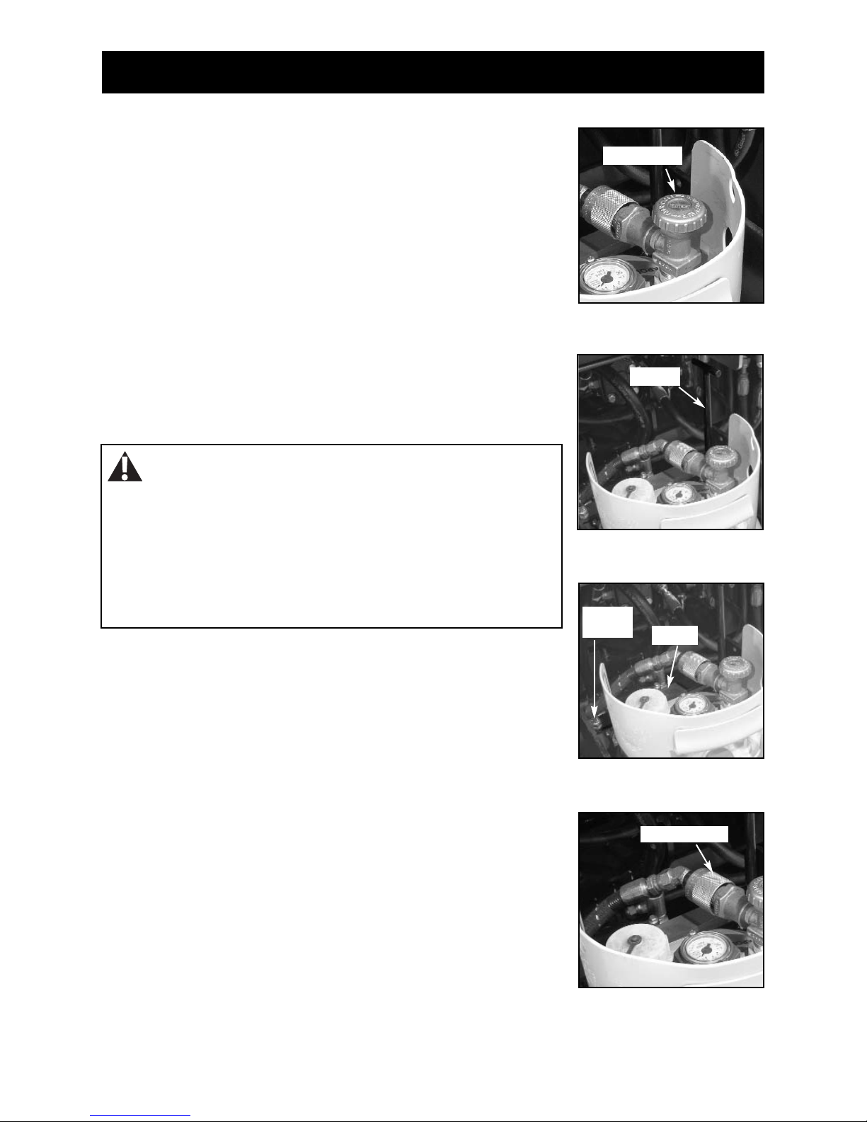
CYLINDER LIFT (FIGURE A)
The cylinder lift lever raises and lowers the cylinder and cutting head. After setting slide plate to proper
height, use the cylinder lift lever to set blade to proper cutting angle. Pull back on the cylinder lift lever
to raise the cutting head. Push the cylinder lift lever forward to lower the cutting head. Continuing to
push the cylinder lift lever forward and it will adjust the angle of the cutting head. This will also jack up the
front of the machine (See Figure B). This will need to be done when doing maintenance on the machine
(ie: wheel changing, front caster maintenance etc). When doing machine maintenance, besides raising
the cutting head angle, place blocks under the machine (See Figure C). Never use the cutting head only.
Figure A
Figure B
WARNING: Disarm machine by removing the cutting head or dropping the cutting head to the
floor when the machine is not in use.
Figure C
SEAT SWITCH
The seat has a safety switch. Operator must be properly positioned for machine to run.
WARNING: Do Not alter a switch or lever. Do Not defeat a safety device.
HYDRAULIC LEVERS (CONTINUED)
• Move levers slowly.
• Both levers forward move the machine forward.
• Both levers backward move the machine backward.
• The left lever forward and the right lever backward
turn the machine quickly to the right.
• The left lever backward and the right lever forward
turn the machine quickly to the left.
• Only using the left or right lever forward , turns the machine slowly to the right or left.
• Only using the left or right lever backwards , turns the machine slowly to the left or right.
• Correcting direction while moving forward is accomplished by slightly reducing pressure on
one lever or the other while moving.
• The center position on levers causes wheels to lock-up.
• Always chock wheels and tie down machine when transporting.
**Control levers are low in vibration.
CYLINDER LIFT

Page 21
OPERATING CONTROLS
WARNING: Engine, exhaust system and hydraulic component temperatures could be in
excess of 200° F causing severe burns if touched.
SHUT DOWN MODE (SHUT DOWN PROCEDURE/ TURNED OFF)
Definition:
State or condition of the 5600 Propane Ride-On that minimizes the danger of mechanical, electrical,
pneumatic or hydraulic hazards.
PUTTING THE 5600 PROPANE RIDE-ONINSHUT DOWN MODE:
• Move the 5600 to level ground
• Turn off the ignition switch and remove the key
• DO NOT move hydraulic levers. The hydraulic system is the brake system. Moving levers could cause
machine to roll, causing damage to machine, property damage and/ or bodily injury
• Wait until motor has stopped completely
• Close propane tank valve (Figure A)
• Let the engine, exhaust system and hydraulic components cool down before performing maintenance
on the machine
Figure A
Propane
Tank Valve
MACHINE STORAGE
• Follow Shut Down Mode procedure
• After engine has completely cooled down, disconnect propane line
• Remove negative terminal on battery
NOTE: IF MACHINE IS NOT RUNNING BUT THE KEY IS IN THE IGNITION AND IN ON POSITION, THE
HOUR METER WILL CONTINUE TO RUN
Page 22
OPERATING CONTROLS
CHANGING PROPANE TANK
TO CHANGE THE PROPANE TANK:
• Turn machine off
• Shut propane tank off (Figure A)
• Release hood strap
• Remove T-handle bolt (Figure B)
• Release tank bracket (bracket does not need to be removed, it
will swing back) (Figure C)
• Disconnect propane hose (Figure D)
• Remove tank and replace
• Follow steps in reverse order
Figure A
Figure B
Figure C
Figure D
Shut Off Valve
T-Handle
T-Handle
Bolt
Bracket
Disconnect Here
WARNING: Ventilation is required in confined work
environments. CARBON MONOXIDE IS A VERY TOXIC,
COLORLESS AND ODORLESS GAS. When engines operate in
enclosed spaces, such as warehouses, buildings under construction,
or tunnels, carbon monoxide can accumulate quickly and reach
concentrations that are dangerous for humans. It causes headaches,
dizziness, lethargy and death. CO is usually the major concern
whenever LPG engines are used indoors
CARBON MONOXIDE DETECTOR
Included with the 5600 are a 75007 Lapel CO Monitor and a 75008 Clip. It is
recommended that the operator and anyone in the working vicinity wear the
detector. Failure to do so could cause bodily injury and/or death. The use of
detectors helps to verify if work area is safe from Carbon Monoxide poisoning.
The detector has an adhesive strip on the back for mounting or can be worn with
the included clip. It can detect as little as 100ppm (part per million) carbon
monoxide gas at approximate relative humidity range of 33 to 50%. If the
humidity is very high it can detect concentrations as low as 20ppm. The
presence of CO will change the impregnated silica color change from red to
red/brown and then to gray/black as the concentration levels increase. Once the
detector is exposed to fresh air, it will return back to red. Shelf life in an
unopened pack is approximately two to three years (expiration date is visible
through unopened package on the back). Once opened it should be replaced
approximately every ninety days. Write date opened in provided area on the
front of the detector. Read further user directions on the back of the detector.

Page 23
OPERATIONAL TIPS
CASTER
Keep clean and free of debris, make sure it can move freely. Clean as needed. Inspect before each use.
Grease once a month.
Moving a "weighted" machine only on the front caster and not on the cutting head or the Front Wheel
Assembly can seem to make the machine turn sluggish. It might turn hard to the right or the left. This is
normal.
FOOT PEG
Keep feet resting and secured on foot pegs when operating machine. Foot pegs are adjustable. Make
sure securing nut is securely tightened
SEAT
Always be properly seated before operating machine. Machine will not run if the operator is not properly
seated
DISARM MACHINE
Remove blade or drop cutting head to the floor when machine is not in use.
TURN MACHINE OFF
Never change cutting head or service blade while machine is running.
LEAKAGE
Keep fittings and hoses tight. If a leak is noticeable, retighten fitting. If leakage persists, remove the
connection and inspect.
ANGLE OF THE HEAD IS SET STEEP
When raising the front of the machine to a steep angle, the bottom of the slide plate should be raised so it
is higher or even with the bottom of the guide channels, 6” to 7” off the floor. This will allow for a steep
blade angle without tipping the machine too far back (usually used for re-scrape). The most common
mode for take up, is the slide plate is almost to the floor (1/4” to 1/2” from the floor).
RAISING OR LOWERING THE SLIDE PLATE
This will only work without a cutting head inserted in the machine. Completely loosen slide plate bolts.
Use cylinder lift lever to raise or lower machine to move slide plate up or down.
WARNING: Always disconnect on board charger before operating machine.

Page 24
LOADING/UNLOADING
• Always remove blade and cutting head when machine is being moved or transported
• Cutting head and slide plate can be removed to make the machine more compact.
• NEVER leave machine unattended on an incline.
• Removing added weights help to make the machine easier and safer to move in and out of a vehicle.
DOCK HEIGHTS
It is best to load or unload the machine from a level/equal dock height (a van from a van dock height, a
truck/semi from a regular dock height).
POWER-GATE
A power-gate can be used when the dock height is not available. Make sure gate is properly rated for
2300 lbs. Make certain the machine is secure so it does not roll off the power-gate. To better secure
machine, raise machine onto the lowered cutting head, raising machine off the caster. Tie machine down,
chock wheels.
RAMPS
To be safe, the ramp needs to be very long to accommodate the machine being loaded/unloaded.
Remove added weight. Make sure ramp is secured. Do not have at a steep incline. The use of a power
winch or hand come-a-long is much safer. For a van, the ramp should be 12 to 18 feet in length
depending on the depth of the incline. For truck height taller than a van, longer ramps will be needed.
See OSHA guidelines. It is not recommended to drive the machine, connected with power, on a ramp.
Make sure ramp is secure and has good contact before using. Failure to do so could cause ramp to fall
away from the vehicle.
Note: See correct and safe operating angles and center of gravity on page 26.
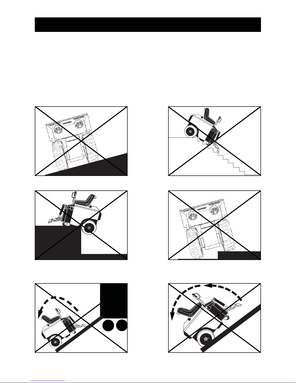
WARNING: Machine has a swivel front caster. Never side hill (See Figure A). The machine on a
incline without power, the front caster will cause machine to swing to the lowest point. If it is necessary
to run machine on an incline, run machine on cutting head. Place at least a 8'' cutting head in
machine. To keep from damaging floor, clamp a piece of carpet into cutting head to slide on the floor.
This will give positive contact with the floor when power is disengaged from the wheels.
Figure A
CAUTION: DO NOT “SIDEHILL”
CAUTION: MACHINE IS BACK HEAVY.
DO NOT RUN ON STEEP INCLINE--
THIS COULD CAUSE MACHINE TO TIP OVER!
Page 25
LOADING/UNLOADING
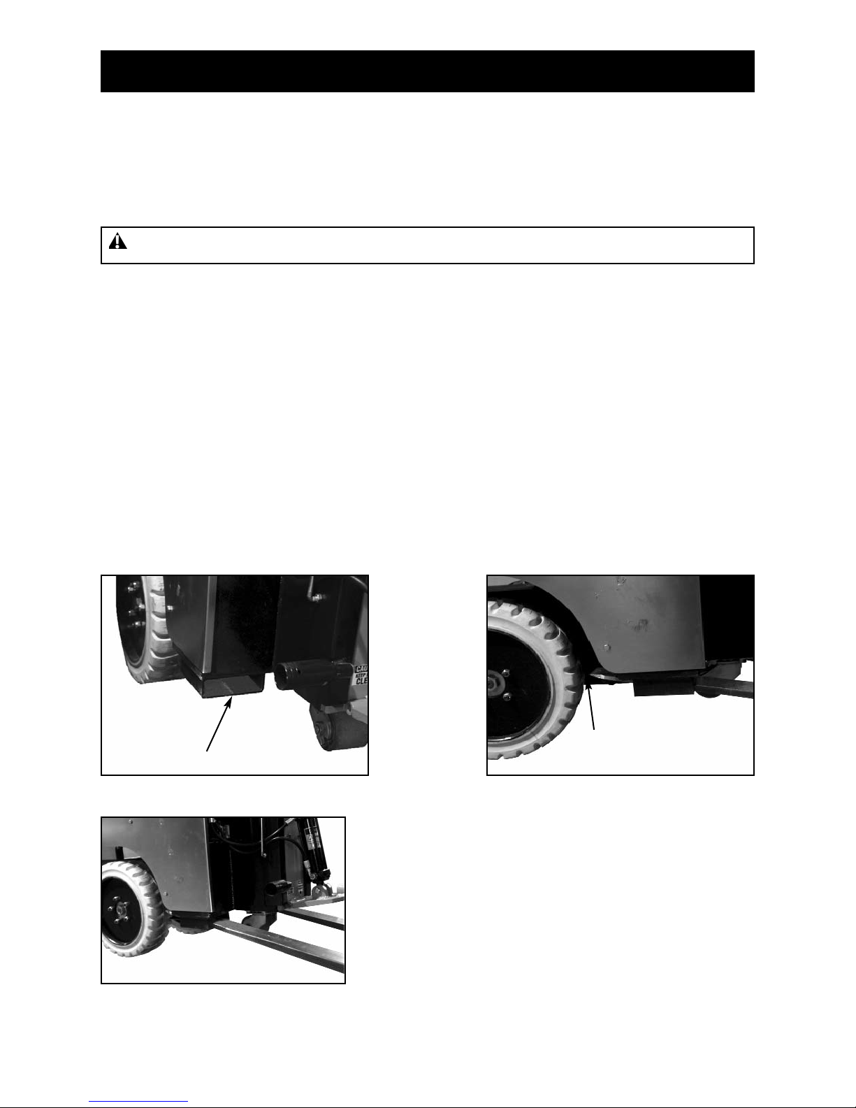
FORKLIFT CUPS
There are two forklift cups mounted under the front of the machine (See Figure A). Slide fork lift forks
through forklift cups. Slide forks all the way back to touch the rear tire (See Figure B). Before lifting
machine, secure machine to fork lift with heavy 3000 lb. or heavier rope or chain. Tilt forks back to lift
machine (See Figure C).
WINCHES
Winches should be used for safety when loading or unloading with ramps. 2000 lb. winch minimum.
TRANSPORTING
Secure machine down with ratchet straps when transporting the machine. Chock wheels to keep
machine from rolling, hydraulic levers should not be locked in the forward or backward position.
Hydraulic levers should be straight up in the "neutral" position. This helps to lock drive wheels. Lift
machine off swivel caster by lowering cutting head for better stabilization. Proper securing straps need to
be rated at least twice the weight of the machine.
WHEEL CHOCKS
Wheel chocks will help to secure the machine but DO NOT use wheel chocks alone to secure the
machine.
Fork Lift Cup
Figure A
Forks on forklift should go
back to the rear wheel
Figure B
Figure C
WARNING: Never tilt machine forward. It could slide off fork lift forks.
Page 26
CENTER OF GRAVITY
Be aware of your surroundings and machines operating angles. When changing from a low slide plate to
a high slide plate setting or a low cutting head angle to a high cutting head angle, the operating “attitude”
of the machine changes. When a floor surface is not level (ramps, inclines, large amounts of debris which
would lift the drive wheel of the machine, etc.), the center of gravity changes. Too much of an angle could
make the machine unsafe (a cause for tip-over). Do Not run the machine in unsafe environments.
CAUTION: MACHINE IS BACK HEAVY.
DO NOT RUN ON STEEP INCLINE--
THIS COULD CAUSE MACHINE TO TIP OVER!
CAUTION: MACHINE IS BACK HEAVY.
DO NOT RUN ON STEEP INCLINE--
THIS COULD CAUSE MACHINE TO TIP OVER!

Page 27
JOB SITE MOVEMENT
• Always remove blade and cutting head when machine is being moved or transported
• Cutting head and slide plate can be removed to make the machine more compact.
• NEVER leave machine unattended on an incline.
• Removing added weights help to make the machine easier to move.
TAPING WHEELS
Taping the wheels with a wide masking tape helps to prevent damage and dirt to floors during move-in
and move-out.
LEAP FROGGING BOARDS
Leap frogging boards help to protect floors from damage. Use two or three ¼" luan or plywood sheets,
approximately 27" wide by 6' long. Cover one side of the board with a thin a carpet. With the carpet side
to the floor, place a board in front of the machine. Drive onto the board. Set the next board in front of the
machine. As you drive off one board, pick it up and set it in front of the machine.
PALLETIZING
Only use a solid platform pallet. If a solid platform pallet is not available, place a piece of ¾" plywood on
top of a pallet. Using a forklift with the forks inserted in the forklift cups, place machine on pallet. Use
ratchet straps to secure machine to pallet.
FRONT WHEEL ASSEMBLY (FIGURE A)
The Front Wheel Assembly is an optional attachment (#5110-100) that is very helpful when moving the
machine around on a job-site or loading the machine that is not on a pallet. It allows machine stability and
safe transportation over most surfaces. It is easy and quick to attach or detach. Raise slide plate so the
bottom of the slide plate is higher or even with the bottom of the guide channels. Raise cylinder, insert
Front Wheel Assembly into cutting head. Secure with securing pin.
Figure A
CAUTION: When moving the slide plate, be aware of pinch point at the bottom of the plate.Failure
to do so could cause serious bodily injury.
WARNING: Protect others in work area. Provide barriers or shields as needed to protect
others from debris and machine operation. Operator should be aware of who is around them and
their proximity.
Pinch Point
Note: Make sure the plate is parallel with the floor so the caster
swivels freely.
Caster
Plate
 Loading...