

National 505 PANTHER PLUS, 500 PANTHER Instruction Manual

#505 PANTHER
PLUS
®
FLOOR
STRIPPER
INSTRUCTION MANUAL
READ MANUAL BEFORE OPERATING MACHINE
9250 XYLON AVENUE NORTH • MINNEAPOLIS, MN 55445 • U.S.A.
800-245-0267 • 763-535-8206 • FAX 763-535-8255 • FAX 800-648-7124
WEB SITE: www.nationalequipment.com • E-MAIL: info@nationalequipment.com
National
Flooring Equipment, Inc.

Page 2
TABLE OF CONTENTS
Table of Contents ........................................................................................................2
Rules for Safe Operation..........................................................................................3-6
A. Grounding ............................................................................................................5
B. Extension Cords ..................................................................................................6
General Operation..................................................................................................7-10
A. Assembly ..........................................................................................................7-8
B. Wheel Adjustment ................................................................................................8
C. Handle Adjustment ..............................................................................................9
D. Machine Operation ..............................................................................................9
E. Machine Start Up Procedure ................................................................................9
F. User General Information................................................................................9-10
G. Transportation ....................................................................................................10
Blades ..................................................................................................................11-16
A. Blade Changing ..................................................................................................11
B. Blade Setting ................................................................................................11-12
C. Types of Tearouts..........................................................................................13-14
D. Blade Diagram....................................................................................................15
E. Blade Chart ........................................................................................................16
Maintenance ..............................................................................................................17
A. Maintaining Equipment ......................................................................................17
B. Cleaning ............................................................................................................17
C. Repairs ..............................................................................................................17
Troubleshooting ........................................................................................................18
Complete Parts List ..............................................................................................19-20
Part Numbers and Diagrams................................................................................21-22
A. External Parts ....................................................................................................21
B. Wheel Parts/Motor Parts ................................................................................21.1
B. Internal Parts......................................................................................................22
Labels ........................................................................................................................23
Guarantee..................................................................................................................24
Return Sheet ............................................................................................................25
Blade Order Form..........................................................................................................

Page 3
RULES FOR SAFE OPERATION
READ AND SAVE ALL INSTRUCTIONS FOR FUTURE USE. Before use, be sure everyone operating this
equipment reads and understands this manual as well as any labels packaged with or attached to the tool.
1. KNOW YOUR POWER TOOL: Read this manual carefully to learn your equipments applications and
limitations as well as potential hazards associated with this type of equipment.
2. GROUND YOUR TOOL: Unless your tool is double insulated, it should be grounded. See Grounding.
3. AVOID DANGEROUS ENVIRONMENTS: Do not use in rain, damp or wet locations, or in the
presence of explosive atmospheres (gaseous fumes, dust or flammable materials). Remove materials
or debris that may be ignited by sparks.
4. KEEP WORK AREA CLEAN AND WELL LIT: Cluttered, dark work areas invite accidents.
5. DRESS PROPERLY: Do not wear loose clothing.These may be caught in moving parts. When
working outdoors, wear rubber gloves and insulated non-skid footwear. Keep hands and gloves away
from moving parts.
6. USE SAFETY EQUIPMENT: Everyone in the work area should wear safety goggles or glasses
complying with current safety standards. Wear hearing protection during extended use and a dust
mask for dusty operations. Hard hats, face shields, safety shoes, etc. should be worn when specified
or necessary.
7. KEEP BYSTANDERS AWAY: Children and bystanders should be kept at a safe distance from the
work area to avoid distracting the operator and contacting the tool or extension cord. Operator should
be aware of who is around them and their proximity.
8. PROTECT OTHERS IN THE WORK AREA: Provide barriers or shields as needed, to protect others
from debris.
9. USE PROPER ACCESSORIES: Using accessories that are not recommended may be hazardous.
Be sure accessories are properly installed and maintained. Do not delete a guard or other safety
device when installing an accessory or attachment.
10. CHECK FOR DAMAGED PARTS: Inspect guards and other parts before use. Check for
misalignment, binding of moving parts, improper mounting, broken parts and any other conditions that
may affect operation. If abnormal noise or vibration occurs, turn the tool off immediately and have the
problem corrected before further use. Do not use a damaged tool. Tag damaged tools “DO NOT
USE” until repaired. A guard or other damaged parts should be properly repaired or replaced. For all
repairs, insist on only identical National replacement parts.
11. REMOVE ALL ADJUSTING KEYS AND WRENCHES: Make a habit of checking that the adjusting
keys, wrenches, etc. are removed from the tool before turning it on.
12. GUARD AGAINST ELECTRIC SHOCK: Prevent body contact with grounded surfaces such as pipes,
radiators, ranges and refrigerators. When making cuts, always check the work area for hidden wires
or pipes. Hold your tool by insulated nonmetal grasping surfaces. Use a Ground Fault Circuit
Interrupter (GFCI) to reduce shock hazards.
13. AVOID ACCIDENTAL STARTING: Be sure your tool is turned off before plugging it in. Do not use a
tool if the power switch does not turn the tool on and off.
WARNING: When using electric tools, always follow basic safety precautions to reduce the risk of
electric shock and personal injury.

Page 4
RULES FOR SAFE OPERATION
14. DO NOT FORCE TOOL: Your tool will perform best at the rate for which it was designed. Excessive
force only causes operator fatigue, increased wear and reduced control.
15. KEEP HANDS AWAY FROM ALL CUTTING EDGES AND MOVING PARTS.
16. WEAR GLOVES WHEN CHANGING BLADES.
17. DO NOT ABUSE CORD: Never unplug by yanking the cord from the outlet. Pull plug rather than cord
to reduce the risk of damage. Keep the cord away from heat, oil, sharp objects, cutting edges and
moving parts.
18. DO NOT OVERREACH. MAINTAIN CONTROL: Keep proper footing and balance at all times.
Maintain a firm grip.
19. STAY ALERT: Watch what you are doing, and use common sense. Do not use a tool when you are
tired, distracted or under the influence of drugs, alcohol or any medication causing decreased control.
20. STARTING MACHINE: On/off switch must be in off position before connecting to power source.
21. UNPLUG TOOL: When it is not in use, unplug tool before changing accessories or performing
recommended maintenance.
22. MAINTAIN TOOLS CAREFULLY: Keep handles dry, clean and free from oil and grease. Keep
cutting edges sharp and clean. Follow instructions for lubricating and changing accessories.
Periodically inspect tool cords and extension cords for damage. Have damaged parts repaired or
replaced.
23. STORE IDLE TOOLS: When not in use, store your tool in a dry, secured place. Keep out of reach
of children.
24. MAINTAIN LABELS AND NAMEPLATES: These carry important information. If unreadable or
missing, contact National for a free replacement.
25. MACHINE IS HEAVY, DO NOT DROP: Counter weights are heavy. Take caution when removing
or reassembling.
WARNING: Exposure to dust may cause respiratory ailments. Use approved NIOSH or OSHA
respirators, safety glasses or face shields, gloves and protective clothing. Provide adequate ventilation
to eliminate dust, or to maintain dust level below the Threshold Limit Value for nuisance dust as
classified by OSHA.
Page 5
RULES FOR SAFE OPERATION
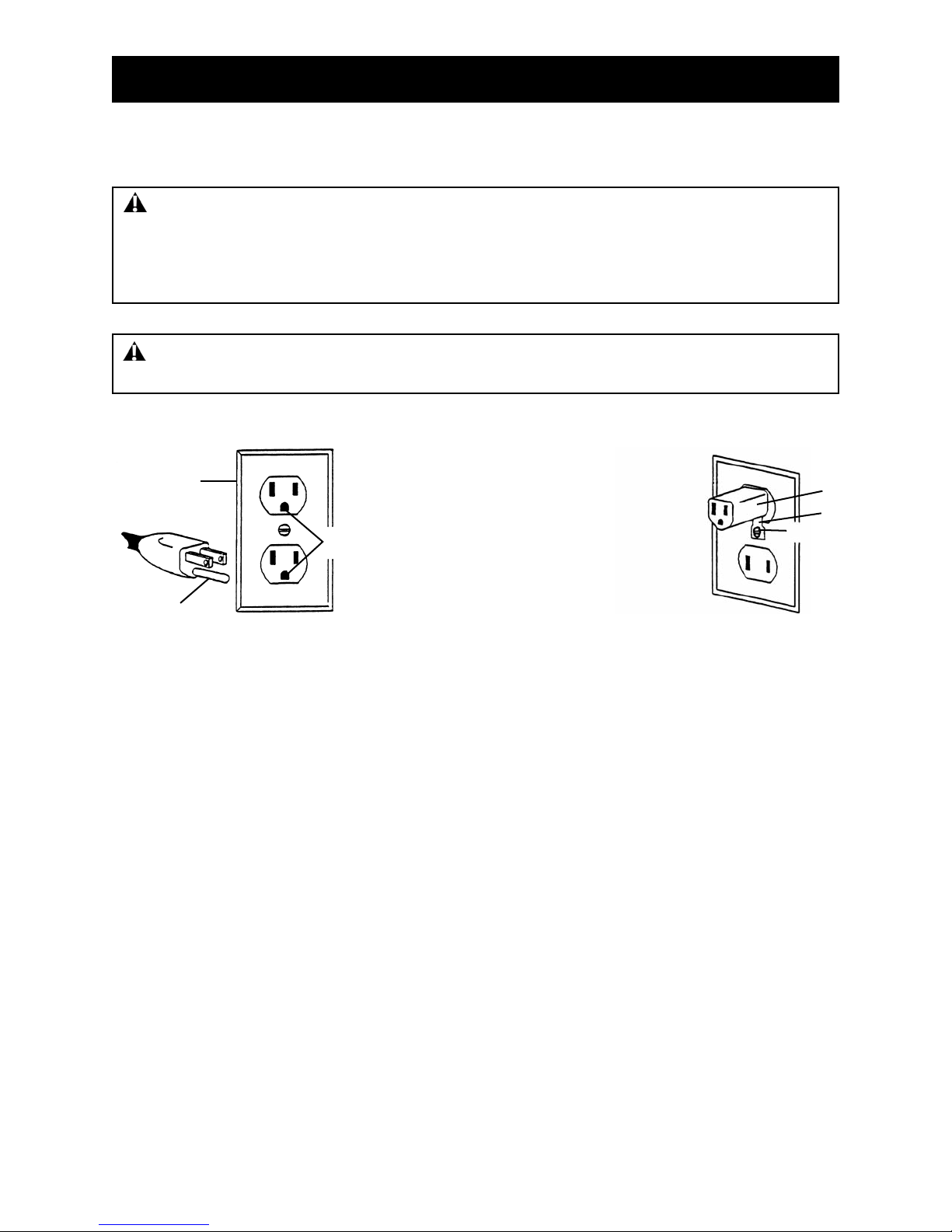
GROUNDED TOOLS: TOOLS WITH THREE PRONG PLUGS
Tools marked “Grounding Required” have a three wire cord and three prong grounding plug. The plug
must be connected to a properly grounded outlet. See Figure A. If the tool should electrically malfunction
or break down, grounding provides a low resistance path to carry electricity away from the user, reducing
the risk of electric shock.
The grounding prong in the plug is connected through the green wire inside the cord to the grounding
system in the tool. The green wire in the cord must be the only wire connected to the tool's grounding
system and must never be attached to an electrically “live” terminal.
Your tool must be plugged into an appropriate outlet, properly installed and grounded in accordance with
all codes and ordinances. The plug and outlet should look like those in Figure A.
Figure B illustrates a temporary adapter available for connecting grounded plugs (Figure A) to two prong
outlets. The green rigid ear or lug extending from the adapter must be connected to a permanent ground
such as a properly grounded outlet box or receptacle. Simply remove the center screw from the outlet,
insert the adapter and reattach the screw through the green grounding ear to the outlet. If in doubt of
proper grounding, call a qualified electrician. A temporary adapter should only be used until a properly
grounded outlet can be installed by a qualified electrician. The Canadian Electrical Code prohibits the use
of temporary adapters.
Figure A
2
1
3
6
GROUNDING
1. Cover of grounded outlet box
2. Outlet ground
3. Grounding prong
4. Temporary adapter
5. Screw
6. Green grounding ear
4
5
Figure B
WARNING: Electrical cords can be hazardous. Misuse can result in fire or death by electrical
shock. Read carefully and follow all directions.
WARNING: Improperly connecting the grounding wire can result in the risk of electric shock.
Check with a qualified electrician if you are in doubt as to whether the outlet is properly grounded. Do
not modify the plug provided with the tool. Never remove the grounding prong from the plug. Do not
use the tool if the cord or plug is damaged. If the plug will not fit the outlet, have a proper outlet
installed by a qualified electrician.

Page 6
RULES FOR SAFE OPERATION
EXTENSION CORDS
Grounded tools require a three wire extension cord. Double insulated tools can use either a two or three
wire extension cord. As the distance from the supply outlet increases, you must use a heavier gauge
extension cord. Using extension cords with inadequately sized wire causes a serious drop in voltage,
resulting in loss of power and possible tool damage.
The smaller the gauge number of the wire, the greater the capacity of the cord. For example, a 14 gauge
cord can carry a higher current than a 16 gauge cord. When using more than one extension cord to make
up the total length, be sure each cord contains at least the minimum wire size required. If you are using
one extension cord for more than one tool, add the nameplate amperes and use the sum to determine the
required minimum wire size.
GUIDELINES FOR USING EXTENSION CORDS
• If you are using an extension cord outdoors, make sure it is marked with the suffix “W-A” (“W” in
Canada) to indicate that it is acceptable for outdoor use.
• Be sure your extension cord is properly wired and in good electrical condition. Always replace a
damaged extension cord or have it repaired by a qualified person before using it.
• Protect your extension cords from sharp objects, excessive heat and damp or wet areas.
• Keep away from water. Do not use if wet.
• Inspect thoroughly before each use. DO NOT USE IF DAMAGED.
• Make sure equipment is OFF before connecting cord outlet.
• FULLY INSERT plug into outlet.
• Do not remove, bend or modify any metal prongs or pins of cord.
• Do not use excessive force to make connections.
• Do not connect a three prong plug to a two-hole cord.
• Avoid overheating. Uncoil cord and do not cover it with any material.
• Do not walk on cord.
• Do not drive, drag or place objects over cord.
READ AND SAVE ALL INSTRUCTIONS FOR FUTURE REFERENCE.
WARNING: Electrical cords can be hazardous. Misuse can result in fire or death by electrical
shock. Read carefully and follow all directions.

Page 7
GENERAL OPERATION
ASSEMBLY
THE PANTHER COMES DISASSEMBLED.
1. Slide switch onto handle leg with switch to the inside of handle (See Figure A).
2. Loosen the top two T-bolts on the handle frame.
3. Insert handle into handle frame (See Figure A) and adjust to desired height
4. Retighten T-bolts on the handle frame.
5. Slide switch upward.
6. Tighten switch box thumbscrew.
7. Loosen T-bolt on adjustment T-bar (See Figure B).
8. Pull up on handle to raise base of machine, engaging wheels to floor surface (See Figure C).
9. Securely Retighten T-bolt on adjustment T-bar.
Figure A
Figure B
Figure C
Switch to inside
of handle
Insert
handle into
handle frame
T-Bolt
Handle frame
T-Bolts
Page 8
ASSEMBLY (continued)
FOR SHIPPING, WHEEL ADJUSTMENT PINS ARE NOT INSERTED CORRECTLY THROUGH
HANDLE FRAME.
1. Remove handle adjustment pins (See Figure A). It may be necessary to maneuver handle so it is not
touching the handle adjustment pins. OR, lay machine onto side (See Figure B).
2. Adjust handle to proper angle (center hole is the most common).
3. Insert handle adjustment pins into desired hole (See Figure C) and secure.
WARNING: Do not operate machine around excessive moisture areas, such as abatement work
and flooded pool areas without GFI wall plug (stock #530 Circuit Guard). Failure to do so could cause
damage in machine or injury to operator.
Figure A
Figure B
Figure C
GENERAL OPERATION
Remove handle
adjustment pins
Insert pin into
desired hole
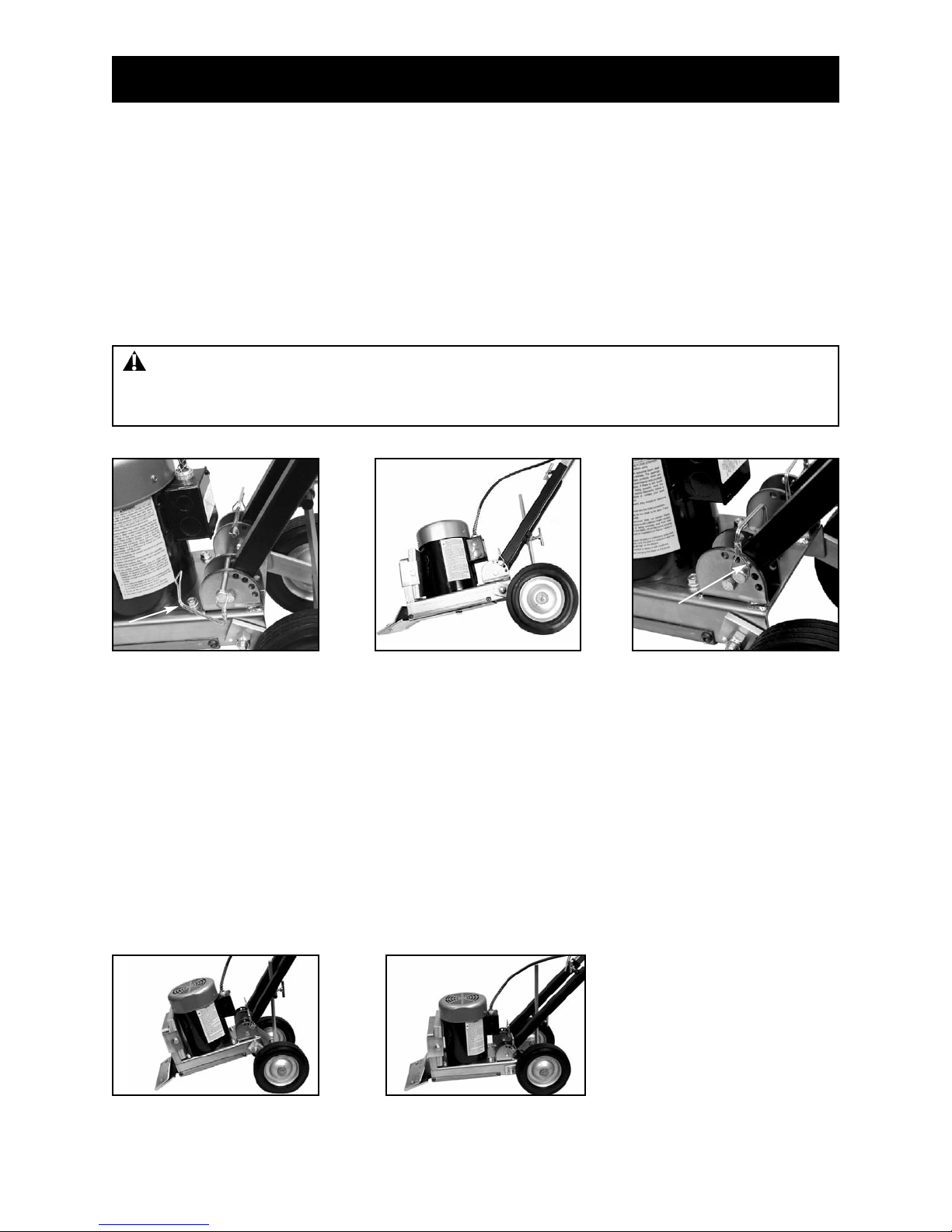
WHEEL ADJUSTMENT
Adjusting wheel angle will change the blade angle to the floor. A steep wheel angle is recommended on
hard tear-outs such as tile over concrete (See Figure D). A low wheel angle is recommended on vinyl
tear-outs and plywood floors (See Figure E).
1. Loosen T-Bolt on adjustment T-bar.
2. Adjust wheels (by handle) to preferred angle.
3. Securely tighten T-bolt on adjustment T-bar.
NOTE: Adjustment by trial at the beginning of a job will give optimum performance.
Figure D Figure E
Steep Angle Low Angle
Lay unit on side
Page 9
GENERAL OPERATION
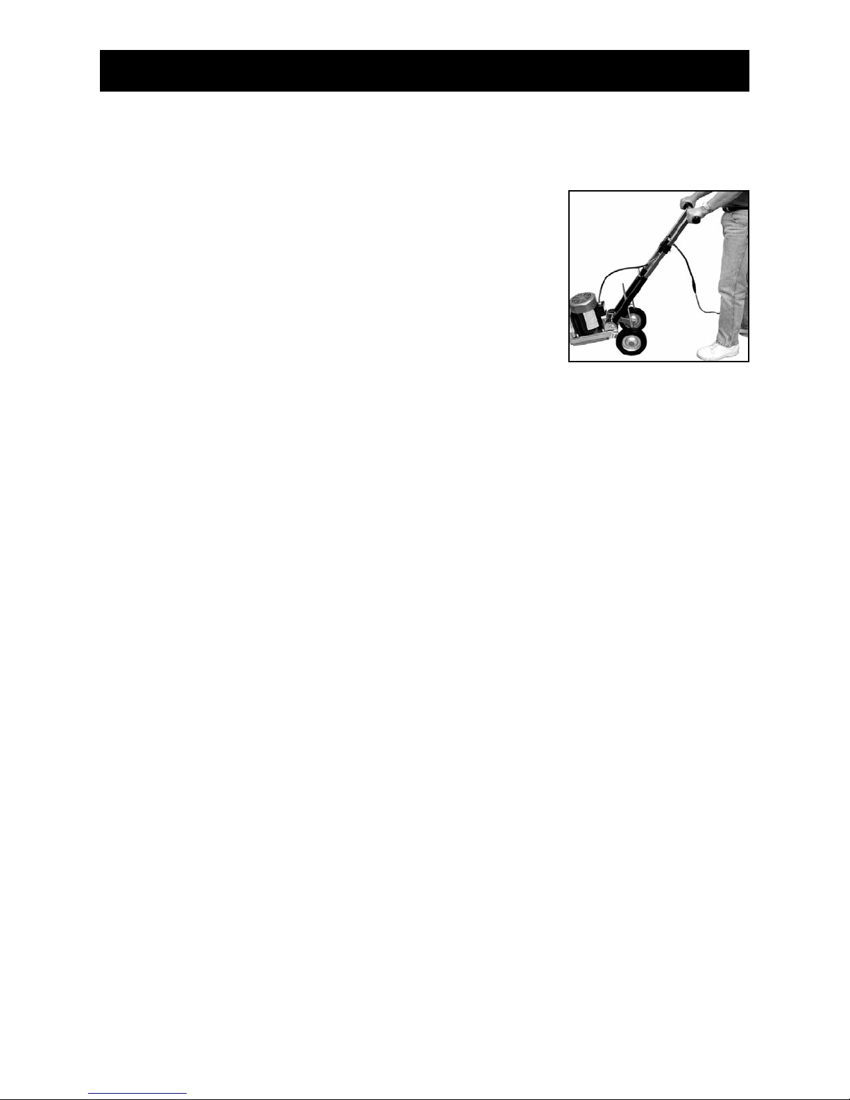
HANDLE ADJUSTMENT
AFTER THE PROPER WHEEL ADJUSTMENT IS ACHIEVED, ADJUST HANDLE BY EITHER A OR B:
A. Removing handle adjustment pins, adjust handle to proper
angle and reinsert handle adjustment pins.
B. Lay machine on side, remove handle adjustment pins, adjust
handle to proper angle and reinsert handle adjustment pins.
No matter what the wheel angle is set at, the handle should be adjusted
to the "belt-line" of the operator or to what the operator is comfortable
with (See Figure A).
- Low setting works best on soft sub floors, plywood, luan,
particleboard and wafer board.
- Higher setting works best on direct glued down carpet, vinyl
or tile on concrete.
NOTE: Adjustment by trail at the beginning of a job will give optimum performance.
MACHINE OPERATION
A well maintained machine is a productive machine. If not properly maintained, it could be unsafe and
could break down. A scheduled maintenance program should insure a long system life and a safe work
environment.
MACHINE START PROCEDURE
TO RUN MACHINE:
1. Machine MUST be off before plugging machine into power source.
2. Plug machine into extension cord and/or outlet.
3. Turn switch to on.
USER GENERAL INFORMATION
1. Always wear eye protection
2. Keep flammable and fragile objects away from this tool.
3. Always check nuts and bolt to make sure they are tight.
4. Always use the tool with proper voltage specified in the machines nameplate.
5. Do not operate around water or wet conditions without use of GFI on cord (stock #530 Circuit Guard).
6. Use properly grounded cord and receptacle.
7. Unplug from power before servicing or changing blades.
8. Use 12-3 or heavier wire cord, not exceeding 50 feet in length.
9. Do not force machine.
10. Do not alter machine.
11. Keep wheels free from debris.
Figure A
 Loading...