

National 425, 425T-440PLL-10, 425T Instructions Manual

National Optical & Scientific Instruments Inc.
6508 Tri-County Parkway
Schertz, Texas 78154
Phone (210) 590-9010 Fax (210) 590-1104
INSTRUCTIONS FOR
425/425T SERIES
STEREOSCOPIC ZOOM MICROSCOPES
Copyright © 5/26/09
National Optical & Sc i entific Instrum ent Inc
A Member of the Motic Group.
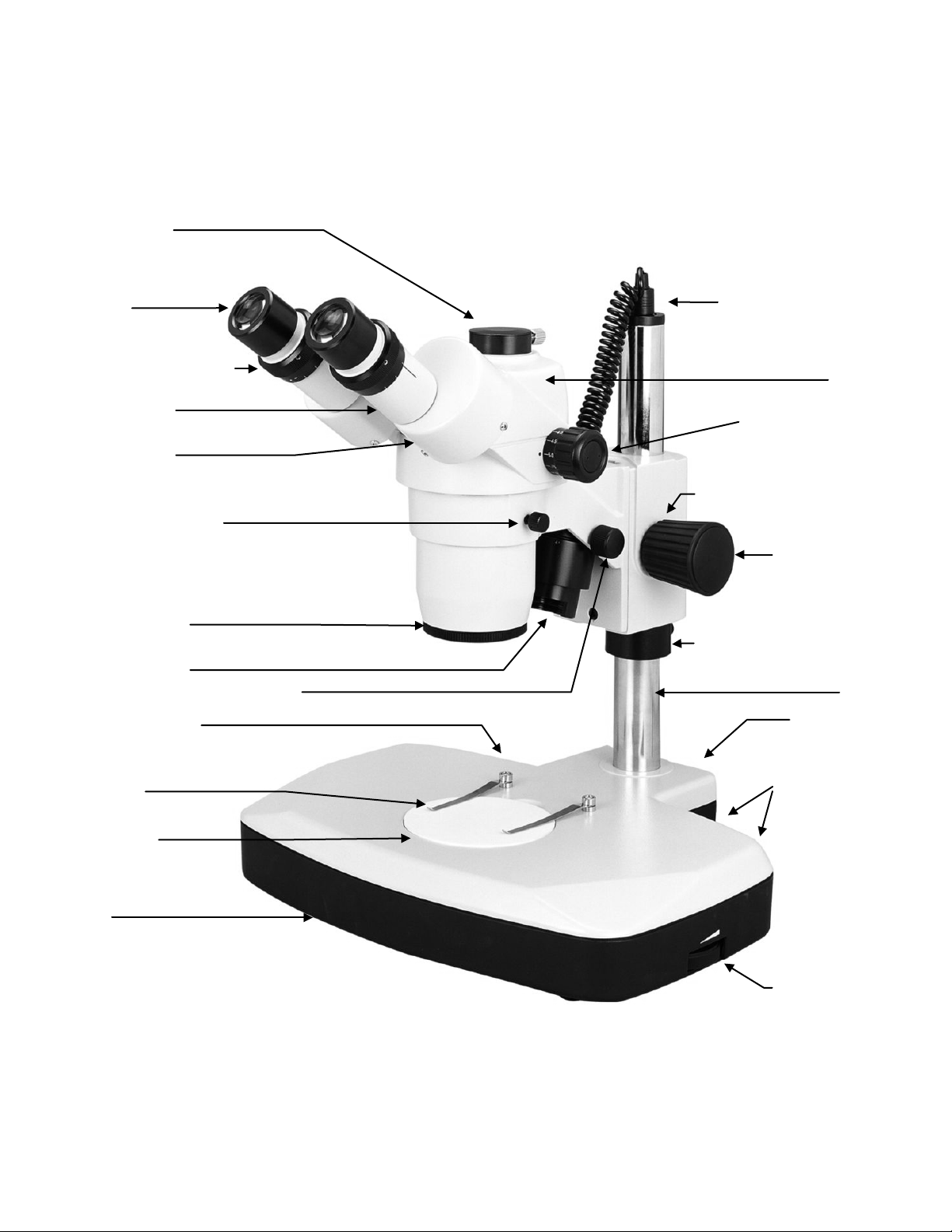
Eyepieces
Zoom Control Knob
Eyepiece Tube
Power Cord for Top Light
Tension Adjustment Collar
Focusing Knob
Focusing Assembly Locking
Post
Intensity Control
Incidental (top)
and Transmitted
(bottom) Light
Switches
Knurled Diopter Adjustment
Head
Head Locking Screw
Knurled Cover Ring
Incidental Illuminator
Top Light Beam Adjustment Screw
Main Power Switch
Stage Clips
Stage Plate
Base
Power Jack
Illustrated: Model 425T-440PLL-10
Prism Housing
Trinocular Port
(on both eyepieces)
(incidental illumi nat i on)
(behind this focusing knob)
(both sides)
Support Collar
for both
illuminators

3
Stereoscopic microscopes are designed for viewing 3-dimensional objects, inspection or assembly of small parts, and for dissection of
biological specimen at low magnification. The 35° inclined viewing head provides an upright, unreversed image which permits easy
manipulation of object being viewed while looking through the microscope. The incidental and transmitted illuminators incorporate
high intensity Lambertain, 5500K color temperature 3 watt LED lamps.
For optimum viewing satisfaction, follow these simple procedures. Nomenclature used to describe components and controls can be
identified by referring to the diagram at left.
UNPACKING
Remove and unpack box A containing the head holder/focusing block mechanism. Remove and unpack box B containing one pair of
eyepieces, 2 each rubber eyeshields, 0.90mm and 2mm “L” hex key wrench, “pin spanner wrench” (used to adjust focusing tension),
95mm frosted stage plate and dust cover. Remove and unpack box C containing zoom head assembly. Remove corrugated stand
retainer C and carefully remove microscope post stand with 90mm diameter black/white contrast plate installed from master carton.
Remove and unpack box D containing AC power cord, 12 volt switching power adaptor.
1. Make certain not to touch any of the lens surfaces while handling the microscope. Dust, dirt, fingerprints can damage the delicate
lens surfaces or adversely affect image quality.
2. Examine packing material before you discard it. Retain the packing boxes in case you need to transport, store, or return the
microscope for service. If it becomes necessary to ship the microscope for any reason, pack it in the original boxes and then pack
these boxes in outer corrugated shipping container for optimum protection. Use of the inadequate packing will not provide
adequate protection in transit, and will void your warranty.
ASSEMBLY
Place the microscope post stand on a flat stable and clean surface.
1. Mounting the focusing assembly to the microscope post stand.
A. Tighten support collar locking screw located on post stand.
B. Loosen focusing block locking screw locate on back of focusing block
C. Slide focusing block over 32mm diameter vertical post of stand
D. Tighten focusing block locking screw
2. Mounting stereo zoom head to stand.
A. Loosen head locking screw.
B. Insert head into the stand (do not force), positioning head to face either forward or backward, whichever suits your preference
or needs.
C. Tighten head locking screw.
3. Remove the black dust caps from the eyepiece tubes and carefully insert the eyepieces.
4. Install rubber eyepiece shields over top of eyepieces.
5. Connect the coaxial plug, from incidental illuminator, into power jack located on top of 32mm diameter post.
6. Plug the 2 pin connector located at one end of AC power cord into receptacle on side of power adapter. Plug other end of AC
cord into appropriate 100 to 240 volt AC outlet (Adaptor automatically adjusts to 12 volt output). Plug the 12 volt DC coaxial plug
into power jack located on rear of microscope base.
OPERATION
1. ILLUMINATION
A. The microscope is furnished with two stage plates. The frosted glass plate is used when viewing transparent specimen slides
or for viewing some specimen thin enough through which light can pass (insect wings, etc.) The plastic black/white contrast
 Loading...