

National 210, 210-RLED Instruction Manual

National Optical & Scientific Instruments Inc.
6508 Tri-County Parkway
Schertz, Texas 78154
Phone (210) 590-9010 Fax (210) 590-1104
INSTRUCTIONS FOR
MODEL 210 (Corded)
MODEL 210-RLED (Rechargeable Cordless)
COMPOUND MICROSCOPE
Copyright © 1/14/2013
National Optical & Sc i ent i fic Instrument I nc.
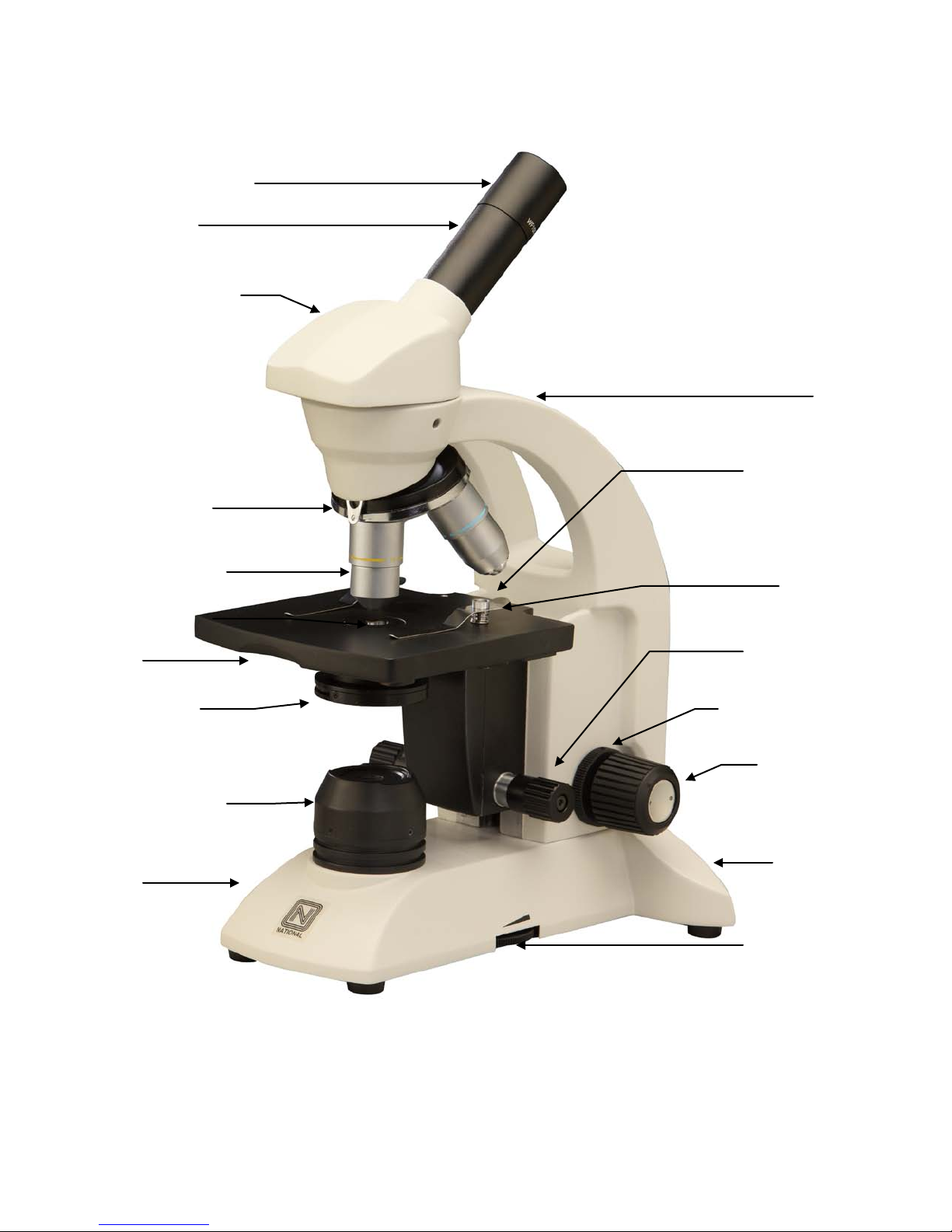
Eyepiece (ocular lens)
Eyepiece tube
Head of microscope
(nosepiece)
Condenser lens
Stage
Illuminator field
Base
Fine focus knob
Rheostat control
On/Off switch
Objective turret
Arm
Safety rack stop
Objective lens
Iris diaphragm
lens housing
Stage clips
Tension adjustment
Coarse focus
knob
and fuse holder
(back of base)

For optimum viewing satisfaction, follow these simple procedures. Nomenclature used to describe components and
controls can be identified by referring to the diagram at left.
UNPACKING
1. Carefully remove microscope, dustcover, 2mm “L” hex wrench (for rack stop adjustment), 0.90mm “L” hex key wrench
(for eyepiece socket set screw, tension adjustment collar and for lamp replacement). Always handle and move
microscope by securely holding the arm of microscope. Avoid touching any of the lens surfaces while handling the
microscope. Dust, dirt, or fingerprints can damage the delicate lens surfaces or adversely affect image quality.
2. Examine packing material before you discard it. Retain the styrofoam container in case you need to transport,
store, or return the microscope for service. If it becomes necessary to ship the microscope for any reason, pack it
in the styrofoam container, and then pack the styrofoam in another corrugated shipping container for optimum
protection. Use of the styrofoam alone will not provide adequate protection in transit, and will void your warranty.
DESCRIPTION OF COMPONENTS
1. EYEPIECE (ocular lens) Lens closest to the eye, magnifies the primary image formed by the objective lens. The
eyepiece is equipped with a “pointer” that rotates as the eyepiece is turned.
2. OBJECTIVE TURRET (nosepiece) Revolving turret which holds objective lenses, permits changes of magnification by
rotating different powered objective lenses into optical path.
3. OBJECTIVE LENS Lens closest to the object being viewed, forms first magnified image of the specimen.
4. STAGE CLIPS Two locked-on clips hold specimen slide in place on stage. Note: Your microscope is already drilled
and tapped to accept an optional mechanical stage. Mechanical stage replaces stage clips and permits precise,
mechanical manipulation of the specimen slide.
5. STAGE Platform of the microscope where the specimen slide is placed.
6. CONDENSER LENS A specially designed condenser lens, fixed in center of stage, condenses light rays from
substage illumination and fills the back lens element of objective lens to improve image resolution.
7. IRIS DIAPHRAGM Iris opening is controlled by lever, designed to help achieve optimum resolution of the objective
lens. Larger apertures used for higher magnifications, and smaller apertures used for lower magnifications. Iris is
protected by a frosted glass covering.
8. SAFETY RACK STOP When properly adjusted, controls maximum upward travel of stage. Prevents higher power
objectives from breaking specimen slides, prevents damage to objective lenses. This stop has been pre-adjusted at
the factory.
9. FOCUSING KNOBS Coarse focusing knobs (larger knobs) located on each side of arm, raise or lower stage to bring
specimen image into focus. Fine focus knobs (smaller knobs) located on each side of arm permit more precise image
adjustment.
10. ILLUMINATION:
210: Built-in substage electric LED illuminator provides constant, reliable, pre-focused illumination equal to a 20-watt
tungsten bulb.
210-RLED: Built-in substage electric LED illum inator provides constant, reliable, pre-f ocusing illumination equal to a
20 watt tungsten bulb. Powered by 3 rechargeable AA nickel metal hydride batteries, no power outlet or electrical cord
is needed.
OPERATION
1. Place microscope directly in front of you in a manner which permits you to comfortably look into the eyepiece. Note
that the head of microscope rotates 360º, permitting you to operate the microscope from the front or from the back,
whichever is most convenient for you. It also permits convenient sharing of microscope by more than one user, by
simply rotating head, without needing to move entire microscope. Most users will position the microscope with the arm
facing them so that focusing knobs are most convenient to reach.
3
 Loading...