

Page 1

National Optical & Scientific Instruments Inc.
6508 Tri-County Parkway
Schertz, Texas 78154
Phone (210) 590-9010 Fax (210) 590-1104
INSTRUCTIONS FOR
167, 168, 169, DC20-169, and 169-BTW1 Series
COMPOUND BIOLOGICAL MICROSCOPES
Copyright © 11/4/2016
National Optical & Scientific Instrument Inc.
Page 2

2
Table of Contents
Introduction / Unpacking 167, 168 and 169 ............................................................................................... 3
Assembly .................................................................................................................................................... 4
Operation .................................................................................................................................................... 5
Installing C-Mount Camera / Maintenance ................................................................................................ 7
Introduction to the DC20-163 .................................................................................................................... 9
Assembly .................................................................................................................................................. 10
Camera Controls and Ports / Connecting Camera to HD Ready Device ............................................... 11
On Screen Display / On Screen Display Control / Live Image and Capture Controls .......................... 13
Image Adjustment Controls ..................................................................................................................... 13
Connecting to Computer / Motic Images Software - PC Full Help Menu ............................................. 15
Motic Images Imaging Module – PC Full Help Menu ............................................................................. 15
Motic Images Software – MAC Full Help Menu ...................................................................................... 16
Introduction to the 169-BTW1 ................................................................................................................. 18
169-BTW1 Assembly / Connecting Camera to Tablet ............................................................ 19
Tablet Operation / Power Management ................................................................................................... 20
Tablet Accessories ................................................................................................................................... 21
Camera Switches and Ports / Connecting to WiFi device / Connecting to WiFi Computer ................. 22
Connecting to Existing WiFi Network ...................................................................................................... 23
Connecting to Networked BTW with MotiConnect App ........................................................................ 25
Connecting to Networked BTW with Motic Images ................................................................................ 27
Tablet Software / MotiConnect Overview / Help Button ......................................................................... 29
Calibration / Transferrig Images to your computer .............................................................................. 30
Motic Images 2.0 ...................................................................................................................................... 31
Motic Images 3.0 ...................................................................................................................................... 33
926 Phase Kit ................................................................................................................................ ............ 34
Cleaning Your Microscope ...................................................................................................................... 36
TroubleShooting ....................................................................................................................................... 38
Optional Accessories and Parts .............................................................................................................. 39
LIMITED LIFETIME WARRANTY ............................................................................................................... 39
Page 3
3
INTRODUCTION
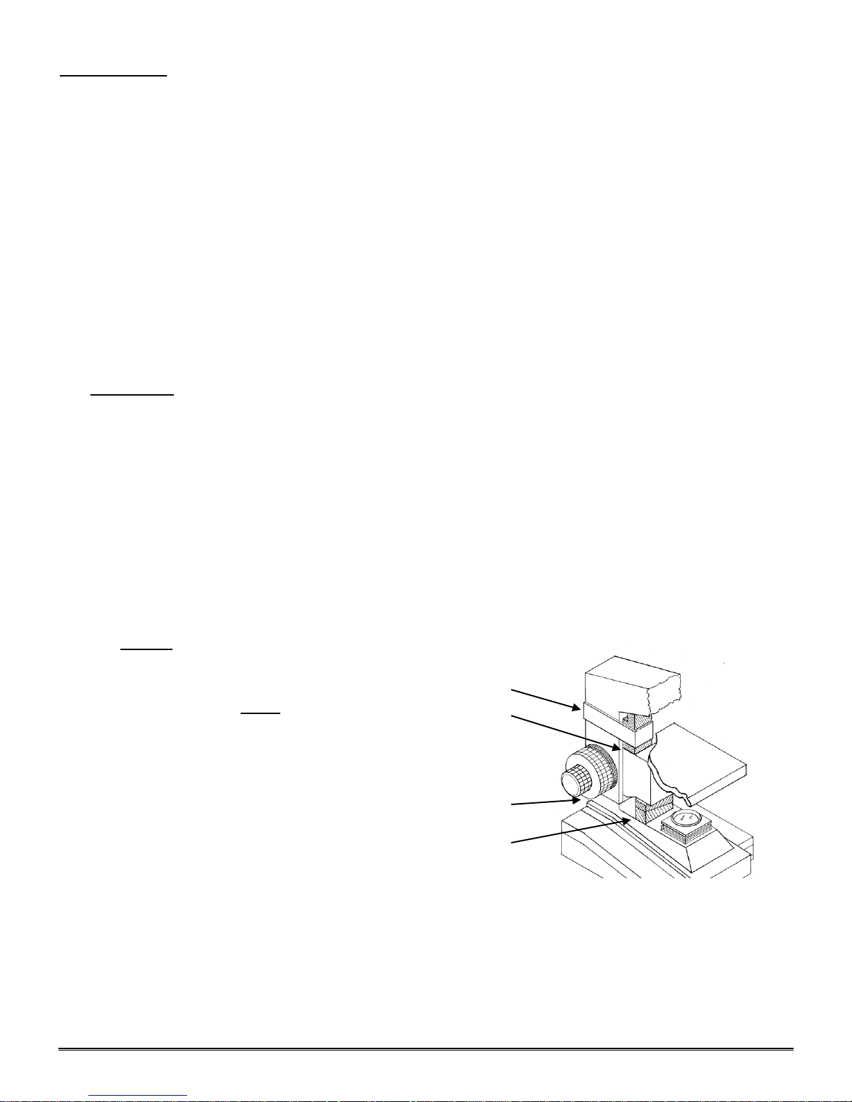
(a)
(b)
(a)
(c)
Thank you for your purchase of a National microscope. It is a well built, precision instrument carefully checked to
assure that it reaches you in good condition. It is designed for ease of operation and years of carefree use. The
information in this manual probably far exceeds what you will need to know in order to operate and maintain your
microscope. However, is provided to answer questions which might arise, and to help you avoid any maintenance
expense that may be unnecessary.
Your new compound microscope is a high performance microscope with high quality achromatic objective lenses
that provide good resolution and optical centering. The microscope is designed with a built-in ball bearing
mechanical stage providing a travel range of 75mm x 50mm in the X and Y direction with graduation reading up to
0.1mm for accurate positioning of specimen. Also included is a ball bearing quadruple nosepiece, precision coaxial
focusing mechanism, rack and pinion mounted N.A. 1.25 Abbe condenser and built-in 3 watt LED variable light
source. Retain the styrofoam container in case the microscope must be transported or returned to factory
for any reason.
Carefully read these instructions before operating microscope. They will permit you to use your new microscope to
its fullest capability. Nomenclature used to describe components and controls is identified by referring to diagram
on page 2.
UNPACKING
The microscope and accessories have been carefully packed to assure they reach you in the best possible
condition. Do not discard the packing container or materials until all components are accounted for. Save the
packing container in case the microscope needs transporting to another location or shipped for repairs.
Components are packed within the container as indicated below.
167 Monocular: Head and Stand, one eyepiece, one rubber eyeshield, 12VDC switching power supply,
operates on 100v-240v, 50H/60H, and dust cover.
168 Binocular head Head and Stand, two eyepieces, two rubber eyeshields, 12VDC switching power
supply, operates on 100v-240v, 50H/60H, and dust cover.
169 Trinocular head Head and Stand, two rubber eyeshields, c-mount, 12VDC switching power supply,
operates on 100v-240v, 50H/60H, and dust cover.
A. Lay container (A) flat and carefully remove microscope head and stand.
NOTICE To protect focus mechanism during
shipment, two black plastic wedges (b)
and one black plastic block (c) are
inserted at strategic points as indicated.
These plastic parts MUST be removed prior
to operating microscope. Failure to do so
will result in damage to focusing mechanism
and will void your warranty.
1. Remove two black Velcro straps (a).
2. Remove wedges (b) by pulling apart the
two parts of wedge in opposite directions.
3. Lower stage by rotating coarse focus
knob, on side of microscope illustrated,
in counter-clockwise direction
4. Remove blocks (c) from stand.
5. These components should be retained with styrofoam container
B. Carefully remove from the stand all tape and packing material used to protect microscope components during
shipment.
C. Un-wrap the components, making certain that lens surfaces do not come in contact with dust, dirt,
fingerprints. Damage to optical surfaces can result from such contaminants, and reduce image quality.
Page 4
4
ASSEMBLY
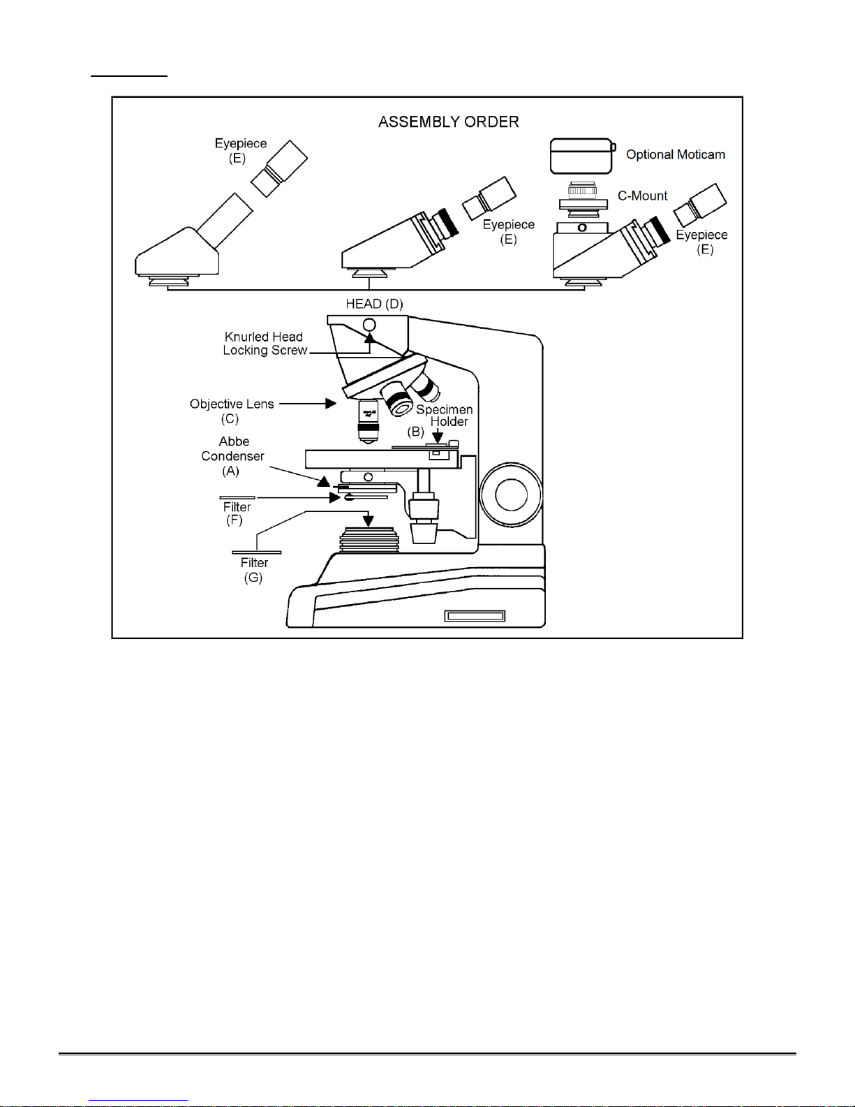
A. Abbe Condenser: Pre-mounted in unit.
B. Specimen holder: Pre-mounted on stage.
C. Objectives: Unless otherwise note, they are pre-mounted on the microscope.
D. Heads: On all series, the head comes pre-mounted to the body of the microscope. Position head so that it
faces either forward or backward, whichever suits your preference or needs, and tighten knurled head locking
screw.
1. Dual viewing teaching head - Mounting vertical eyepiece tube with diopter to head: Loosen knurled
locking screw, remove black dust cap from vertical port. Insert vertical eyepiece tube with diopter into
vertical port. Retighten knurled screw to secure vertical eyepiece tube in place.
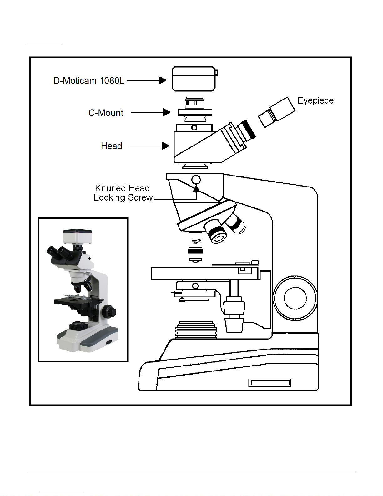
2. Trinocular head - Mounting C-Mount to head: Loosen knurled locking screw, remove black dust cap
from vertical port. Insert C-Mount and retighten knurled screw to secure in place.
a. Trinocular head provided with a three position sliding rod to direct light through microscope. The
three position sliding rod (b) allows user to easily direct microscope image into desired path.
1) Rod pushed completely into head; 100% of microscope image is directed to binocular
eyepieces.
2) Rod at mid-position (pull or push rod until you feel a gentle click stop), 100% of microscope
image is directed to trinocular port.
3) Rod pulled to fully extended position; 30% of image directed to binocular eyepieces, 70%
directed to trinocular port.
Page 5
5
E. Eyepieces: Remove the dust caps from eyepiece tubes. Avoid touching any lens surface and Insert
eyepieces into the eyepiece tubes.
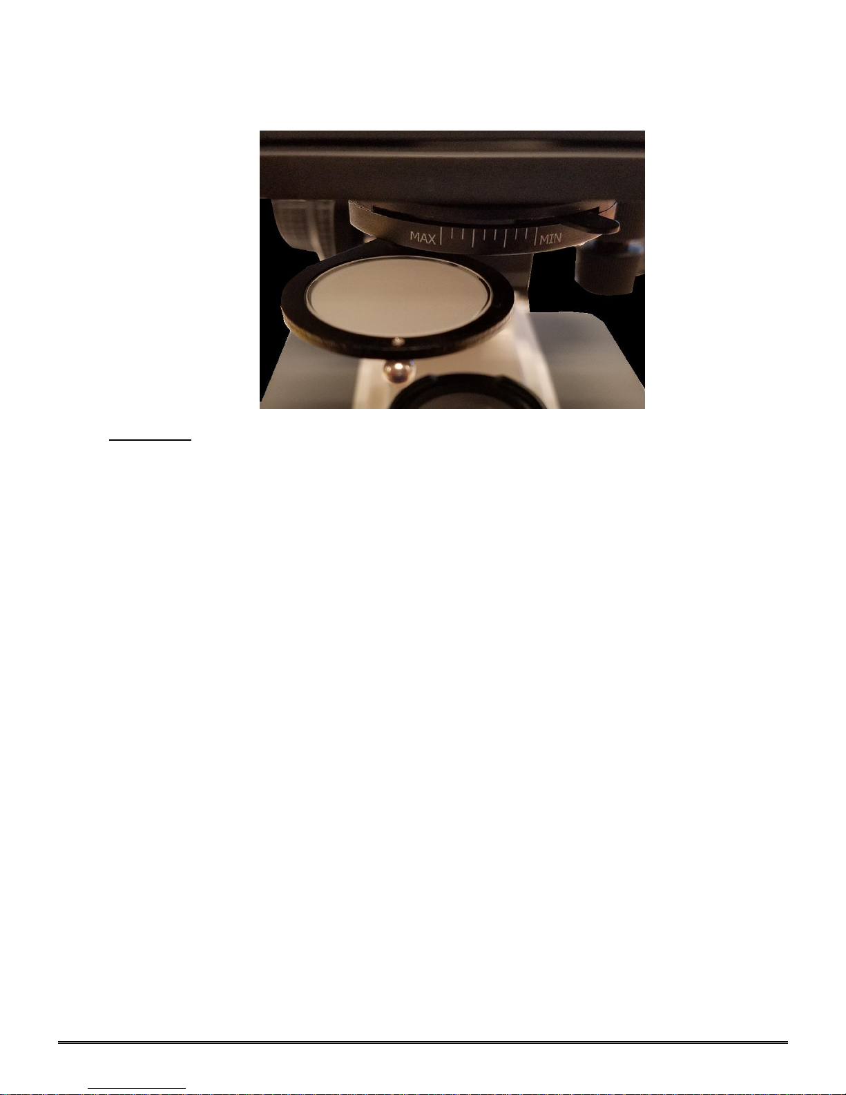
F. Filter: Swing out filter holder has built in frosted filter – must be in place when using the 4x and 10x
objectives.
OPERATION
G. Illumination.
1. Before operating microscope, adjust intensity control located on side of base to the minimum
H. Interpupillary adjustment of viewing head (Models 168 and 169 only)
I. Focusing the microscope.
position. This should be done prior to each time light is turned on or off. This will extend bulb life.
2. Insert power plug into 12VDC switching power converter, then insert plug on other end of converter into
power jack on back of microscope base. Note that the 12VDC converter will operate on either 120v or
240v current, 50 hertz or 60 hertz, eliminating the need for any other transformer.
3. Push rocker switch at rear of base to ON position.
4. Rotate intensity dial on illuminator base until image is illuminated.
5. Adjust intensity of light to match requirements of objective and specimen slide.
6. In case of equipment malfunction, see “Trouble Shooting” procedures.
1. Look through microscope and adjust distance between the two eyepiece tubes by grasping the sliding
mounts to left and right of eyepieces and sliding together or apart.
2. When a full field of view is observed through both tubes, and images blend into one, interpupillary
distance is corrected for your eyes. Check the interpupillary scale and note index reading for future
reference, in case other users will be changing this adjustment from time to time.
3. Adjust the diopter scales, located on each eyepiece tube, to the same numerical value as indicated on
the interpupillary scale. This must be done in order to maintain parfocality of objective lenses. If
interpupillary distance is changed, adjust eyepiece diopters accordingly.
1. Position the 4x objective lens into the optical path, making sure that lens is properly indexed in its clickstop position.
2. Place standard specimen slide (cover slip up) on top of stage surface.Swing moveable finger on slide
holder outward. Place specimen slide against fixed side of slide holder. Slowly release moveable finger
until it makes contact with specimen slide.
3. Rotate coarse focusing controls until specimen comes into focus.
Page 6
6
4. Adjust fine focus controls until specimen is in sharp focus.
Objective Specification Chart
Objective
N.A.
Color Code Ring
Field of View
Magnification
Din 4X
0.10
Red
4.5mm
40X
Din 10X
0.25
Yellow
1.8mm
100X
Din 40X
0.65
Blue
0.45mm
400X
Din 100X
1.25
White
0.18mm
1000X
5. Adjust diopter for difference in eyesight.
a. Using right eye, peer into the right eyepiece tube. Adjust sharpness of image by utilizing fine focus
controls.
b. Using left eye, peer into the left eyepiece tube. Adjust sharpness of image by turning diopter
adjustment located on left eyepiece tube.
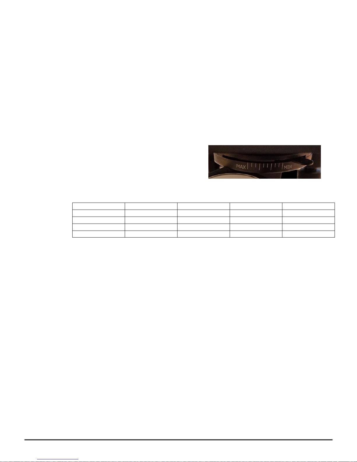
6. Adjusting the aperture (opening) of iris diaphragm.
Iris diaphragm should not be used to control the brightness of illumination, use light intensity control
knob to adjust light level. Iris diaphragms are designed to help achieve high resolution of specimen and
provide contrast in the image. Smaller apertures will deliver higher contrast to image. However, closing
aperture too much will reduce resolution. Experimentation is the best method of determining the correct
opening of diaphragm. Some suggested openings for iris diaphragm are:
OBJECTIVE DIAPHRAGM OPENING
4x 1/8 open (MIN)
10x 1/8 to 1/4 open
40x 1/4 to 1/2 open
100x 1/2 to 3/4 open (MAX)
7. Changing magnification.
a. Rotate revolving nosepiece to position 10x objective into optical path.
b. This microscope has been parfocalized, which allows changes from one objective to another while
requiring only a slight adjustment of the fine focus controls.
c. When changing to the 40x and 100x objective lens, care must be exercised in order to prevent
damaging the front lens element and specimen slide.
d. In order to obtain maximum resolution of the 100x oil immersion lens, it is necessary to apply
immersion oil between the coverglass of slide and front lens of the objective.
1) Use of a very small amount of immersion oil is required. Only the very tip of the lens
should ever come in contact with the immersion oil. Oil should not come in contact
with the white sealant ring on the objective. Excess use of immersion oil will ruin your
objective and void your warranty.
2) All air bubbles must be removed from between lens and slide by rotating nosepiece back and
forth.
8. When finished viewing, all parts that come in contact with oil must be cleaned. Failure to do so could
permanently damage the 100x oil immersion objective lens. Use of Windex to clean immersion oil off
lens surfaces is recommended.
9. Coarse focus tension adjustment.
a. Tension adjustment knob is located between stand and coarse focus knob of microscope, on the
right side.
b. To tighten tension of coarse focus knobs, turn control in a counter-clockwise direction. It is
advisable to leave controls as loose as possible, tightening only enough to keep stage from drifting
down and out of focus. To loosen tension, turn control in clockwise direction.
Page 7
7
INSTALLING C-MOUNT CAMERA (to trinocular model only)
(b)
(c)
(a)
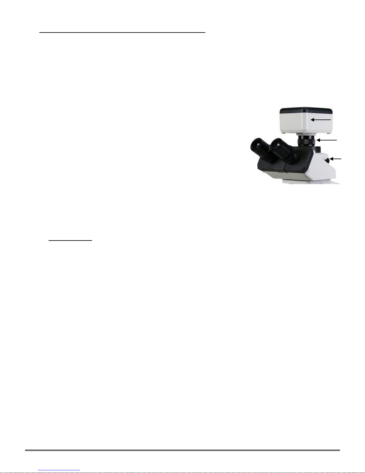
Trinocular model #169 is equipped with a port on top of head. Using the included C-Mount adapter and the
three-position sliding rod (c) allows use to easily direct microscope image into desired path.
1) Rod pushed completely into head; 100% of microscope image is directed to binocular eyepieces.
2) Rod at mid-position (pull or push rod until you feel a gentle click stop); 100% of microscope images is directed
to trinocular port.
3) Rod pulled to fully extended position; 30% of image is directed to binocular eyepieces, 70% directed to
trinocular port.
4) Remove front cap from the D-Moticam c-mount camera. Thread front of
camera onto threads of video adaptor (b).
Locate knurled screw located on side of trinocular port on microscope.
Turn screw counter-clockwise to permit removal of black plastic disk
covering trinocular port.
Insert video adaptor tube into trinocular port. If adaptor does not insert
easily, further loosen knurled screw at side of port until adaptor tube drops
into port and is firmly seated. Retighten knurled screw to secure adaptor
and camera in place. Pull sliding rod (c) until half way extended, to direct
100% microscope image to trinocular port. Proceed with operation of
digital camera and computer/monitor according to manufacturer’s
directions. With the live image on the monitor, slowly rotate the knurled
diopter on “C” adapter until image is in focus on monitor. If microscope
image does not remain in focus when microscope magnification is
changed, recheck digital c-mount camera chip size. Perhaps it will be
necessary to either replace or remove the top “CS” adaptor ring in order for
the video adaptor to be compatible with the chip size of your digital c-mount
camera.
MAINTENANCE
WARNING: FOR YOUR SAFETY, TURN SWITCH OFF AND REMOVE PLUG FROM POWER SOURCE
OUTLET BEFORE MAINTAINING YOUR MICROSCOPE. TO AVOID SHOCK OR FIRE HAZARD, IF
POWER CORD IS WORN, CUT OR DAMAGED IN ANY WAY, HAVE IT REPLACED AT ONCE.
A. OPTICAL MAINTENANCE
1. Do not attempt to disassemble any lens component. Consult an expert technical service company when
repairs not covered by these instructions are required.
2. Prior to cleaning any lens surface, brush dust or dirt off lens surfaces using a camel hair brush. Or use
air to blow dust and lint off surfaces. Use of compressed air in a can, available at any computer supply
store, is a good source of clean air.
3. Cleaning eyepiece lenses. Do not remove eyepiece from eyepiece tube. Clean only the outer surface.
Breathe on lens to dampen surface, then wipe with lens paper. Do not wipe lens surface while dry as
lenses are scratched very easily. Wipe a circular motion from center to outer edges.
4. Cleaning objective lenses. Do not remove objective lenses from microscope. Clean front lens element
only. Using a cotton swab saturated with distilled water, clean front lens surface. Inspect the lens using
a magnifying glass to insure that the element is clean. If immersion oil or specimen material of any kind
is evident, use a cotton swab dipped in a small amount of Windex to clean all foreign material from
objective lens surface. Such material will reduce, or totally block, image quality.
5. Cleaning condenser lens. Clean only the top lens surface, visible when looking through hole in top of
stage. Use same procedure as used for eyepiece or objective lenses.
6. Illuminator condenser lens. Use same procedure as used for eyepiece or objective lenses.
Page 8
8
B. ELECTRICAL MAINTENANCE
WARNING: FOR YOUR SAFETY, TURN SWITCH OFF AND REMOVE PLUG FROM POWER SOURCE
OUTLET BEFORE MAINTAINING YOUR MICROSCOPE.
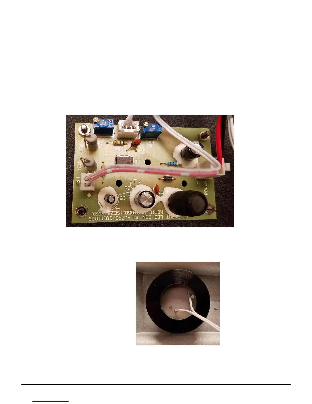
1. Replacement of lamp.
a. Carefully lay instrument on its side, taking care to avoid damage to the specimen slide holder
located on top of mechanical stage.
b. Remove 5ea cross head screws, holding base plate.
c. Carefully lay the base plate flat on the table.
d. Disconnect the LED cable from the plug socket on the LED circuit card.
e. Your microscope requires a 3W LED bulb assembly – Part # 800-500
f. The LED bulb is located within the lamp housing. It is held in place with screw on holder. Simply
unscrew the ring holder to remove the bulb assembly.
g. Assemble the unit in the reverse order.
Page 9

9
Introduction to the DC20-169 Series Microscope
D-Moticam 1080L
Sensor Type CMOS
Sensor Size 1/2.8"
Resolution 2 MP
Capture format (on SD-card) Still Image 1980 X 1080 / Video HD 1980 X 1080
Live Display Mode (through USB) 1980 x 1080
Live Display Mode (through HDMI) 1920 x 1080 (HD) @ 60 fps*
Pixel Size 2.8μm x 2.8μm
Data Transfer HDMI (1080P) and USB2.0
Operating Temperature From-10 to +60 Degrees Celsius non condensing
Slot SD Card (max 32 GB)
Supported OS Microsoft Windows XP/Vista/7/8 and MAC OSX
Minimum Computer Requirements 2GHz dualcore – RAM mem 2GB – Video mem min. 512 MB
Page 10
10
ASSEMBLY
DC20-169 Series
Page 11
11
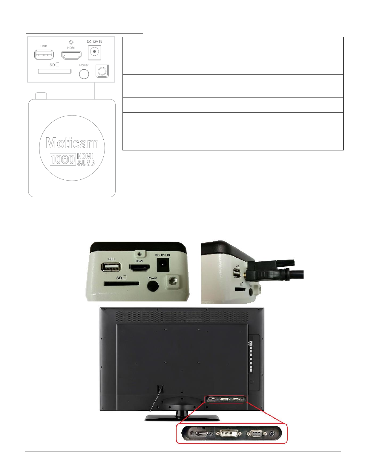
CAMERA CONTROLS AND PORTS
This USB port can also be used to connect a USB mouse so that the
camera can be controlled without a computer. The USB connection can
be used to connect the Moticam 1080 directly to a computer (not
recommended) to be used with the provided Motic Images Plus software.
HDMI port for connecting to an HDMI ready display (the cable is provided
in the Moticam 1080 box).
DC 12V Power port for connecting the included Power Supply.
SD Card slot for capturing images and video files onto an SD card. The
maximum size compatible is 32GB
Pressing this button will turn the camera on and off.
CONNNECTING CAMERA TO HD READY DEVICE
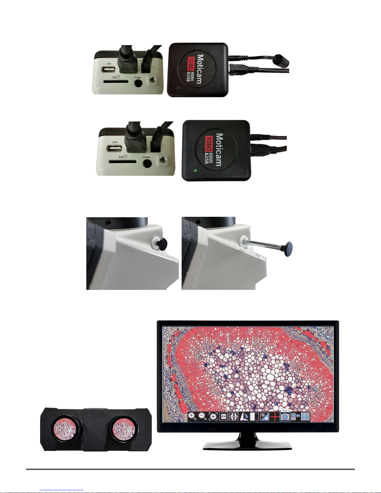
1. Connect the HDMI Cable, included with your camera, to the back of the D-Moticam 1080. Connect one end of
the HDMI cable (end with screw) to the 1080 and then connect the other end of the HDMI cable to the back of
your HD Ready device (Monitor, Projector, HDTV, etc..).
Page 12
12
2. Plug the power cord into the back of the D-Moticam 1080.
3. Then press the power button one time to turn on the camera. The green power indicator should now illuminate.
4. Now make sure your microscope is on and you are focused in on your slide / specimen.
5. On the right hand side of the head, just behind the right eyepiece, is the three position slide bar. The slide bar
must be pulled out until it stops.
6. In this position, the slide should be visible through the eyepieces and displayed on your HD ready device.
Page 13
13
D-Moticam 1080 On-Screen Display
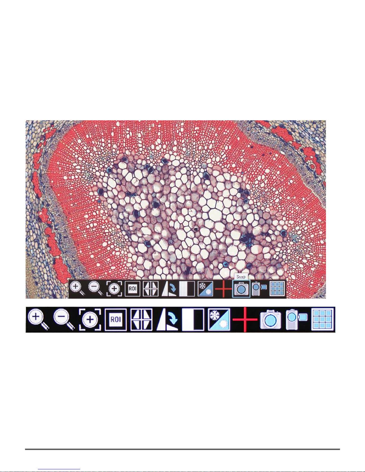
When the camera is connected to an HDMI display and controlled through a USB mouse, you can simply move the
mouse cursor to the right to activate the on-screen function display for capturing images and also for adjusting various
aspects of the image parameters. You can also use this setting to change the on-screen display language from the
default English to Japanese or Chinese.
On Screen Display Controls
When the camera is connected to an HDMI display and controlled through a USB mouse, you can simply move the
mouse cursor to the right to activate the on-screen function display for capturing images and also for adjusting various
aspects. All images can be captured to 32GB (Max) SD card for transfer to computer later.
Live Image and Capture Controls
1. Zoom In: Zooms in on an area of the live image.
2. Zoom Out: Zooms out on an area of the live image.
3. Magnifier: Zooms in (full screen) a selected region of live image.
4. Region of Interest: Allows user to view only a specific area of live image.
5. Mirror: Changes image view vertically or horizontally.
6. Rotate: Rotates the image from 90 to 360 degrees.
7. Split: Compares a capture image with a live image.
8. Freeze: Freeze live image.
9. Crossline: Inserts a crossline on the live image.
10. Snap: Capture image on SD Card as JPEG.
11. Record: Record 1080 video onto SD Card as an AVI.
12. Playback: Watch or look at previous images or videos captured to SD card.
Page 14
14
Image Adjustment Controls
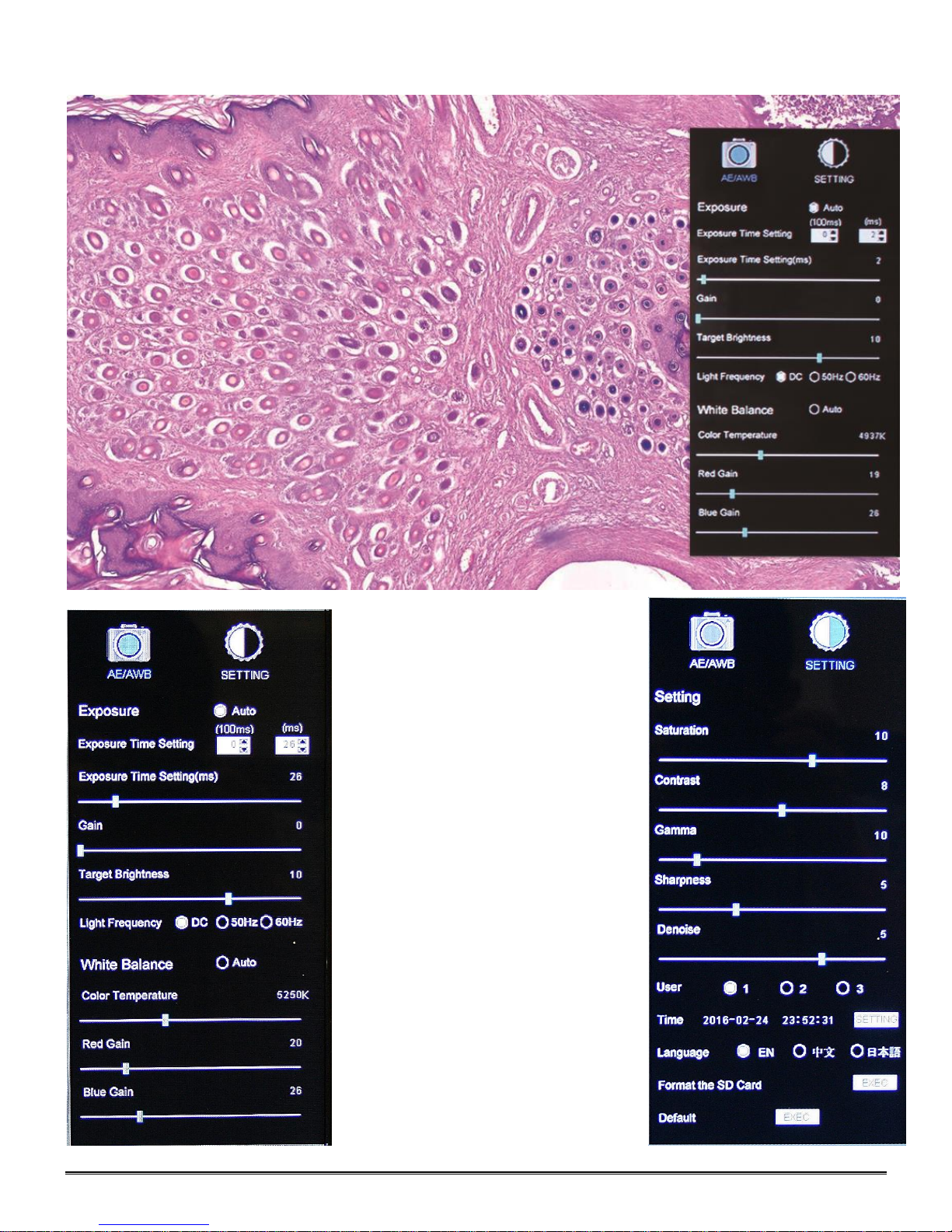
AE/AWB Menu allows you to
adjust:
Exposure, Gain, Gamma,
Brightness, Light Frequency,
White Balance, and Color Temp.
Settings Menu allows you to
adjust:
Saturation, Contrast, Gamma,
Sharpness, Digital Noise, Save
Individual User settings, Time
setting, Language, Format the SD
Card, and Restore all settings to
Default.
Page 15
15
TRANSFERING IMAGES TO YOUR COMPUTER
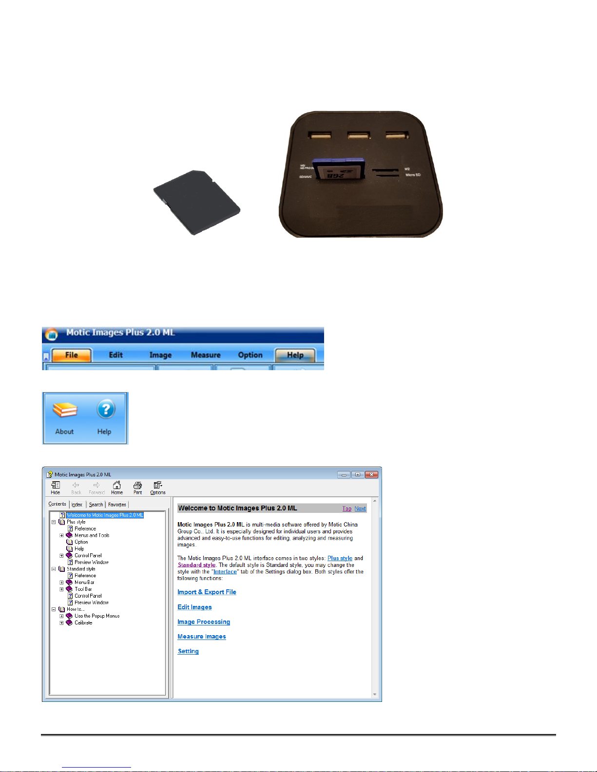
By default all your images are saved to an SD card, purchased separately. If you do not own one already, it is
recommended you also purchase an external SD card reader. This is simplest and easiest way to transfer
images to your computer. Images are automatically captured as Jpeg images. *Please note: 32GB Max*
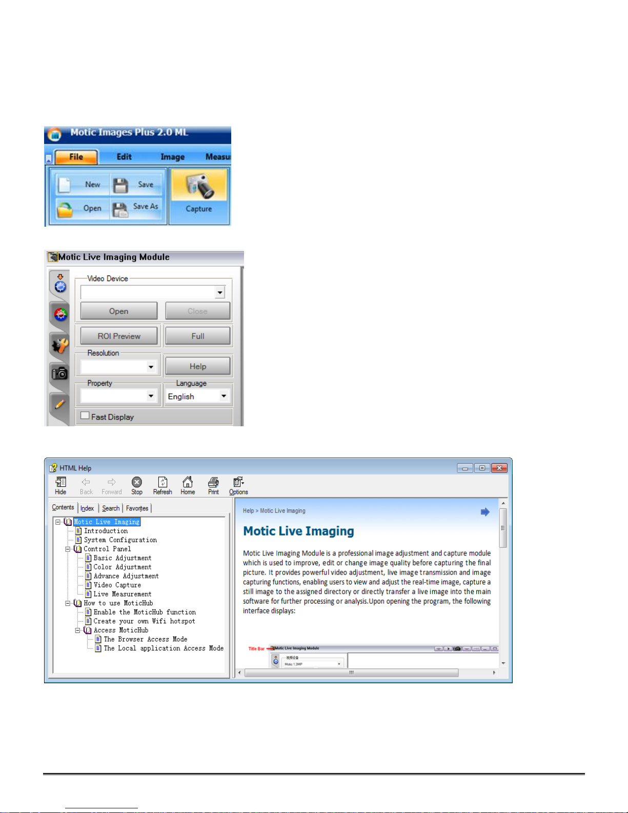
MOTIC IMAGES SOFTWARE – PC Full Help Menu
The full software manual for Motic Images is accessible within the software’s main page.
To begin, open the Motic Images Software.
At the top of main screen find the menu tab labeled Help:
Click on Help and then select the help option:
This will open the Motic Images help file contents, containing the full help menu:
Page 16
16
Motic Live Imaging Module – PC Full Help Menu
The full Live Imaging Module manual is accessible within the live Imaging main page.
To begin, open the Motic Images Software.
At the top of main screen find the menu tab labeled File and click on Capture:
Once the Motic Live Imaging Module has opened, click on Help:
This will open the Motic Live Imaging Module help file, containing the full help menu:
MOTIC IMAGES SOFTWARE – MAC Full Help Menu
The full software manual for Motic Images is accessible within the software’s main page.
To begin, open the Motic Images Software.
At the top of main screen find the menu tab labeled Motic Images Plus Help:
Page 17

17
This will open the Motic Images Help Manual:
Page 18
18
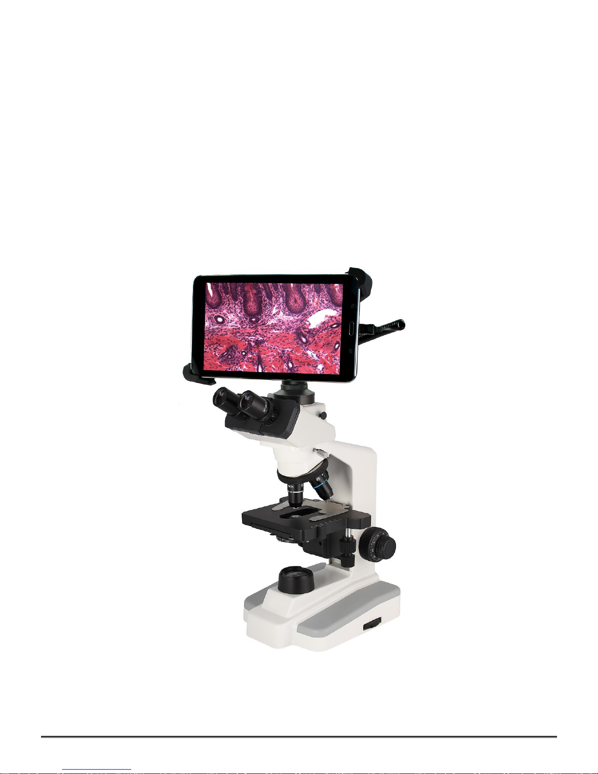
Introduction to the 169-BTW Series Microscope
8" LCD Android tablet with 1280x800 screen resolution
Connection: WiFi; mini HDMI; micro SD card
5.0 MP sensor
5.0 MP captured image resolution
WiFi Resolution: 2.0MP - 5.0MP
720P captured video resolution
HDMI: 1080
Android operating system
WiFi: WiFi output (802.1 ab/g/n supporting both hot-spot mode or using existing WiFi network)
Preloaded optimized MotiConnect app
Supplied with Motic Images Plus software for Mac/PC
Built-in MoticHub allows for wireless sharing
Page 19
19
Assembly
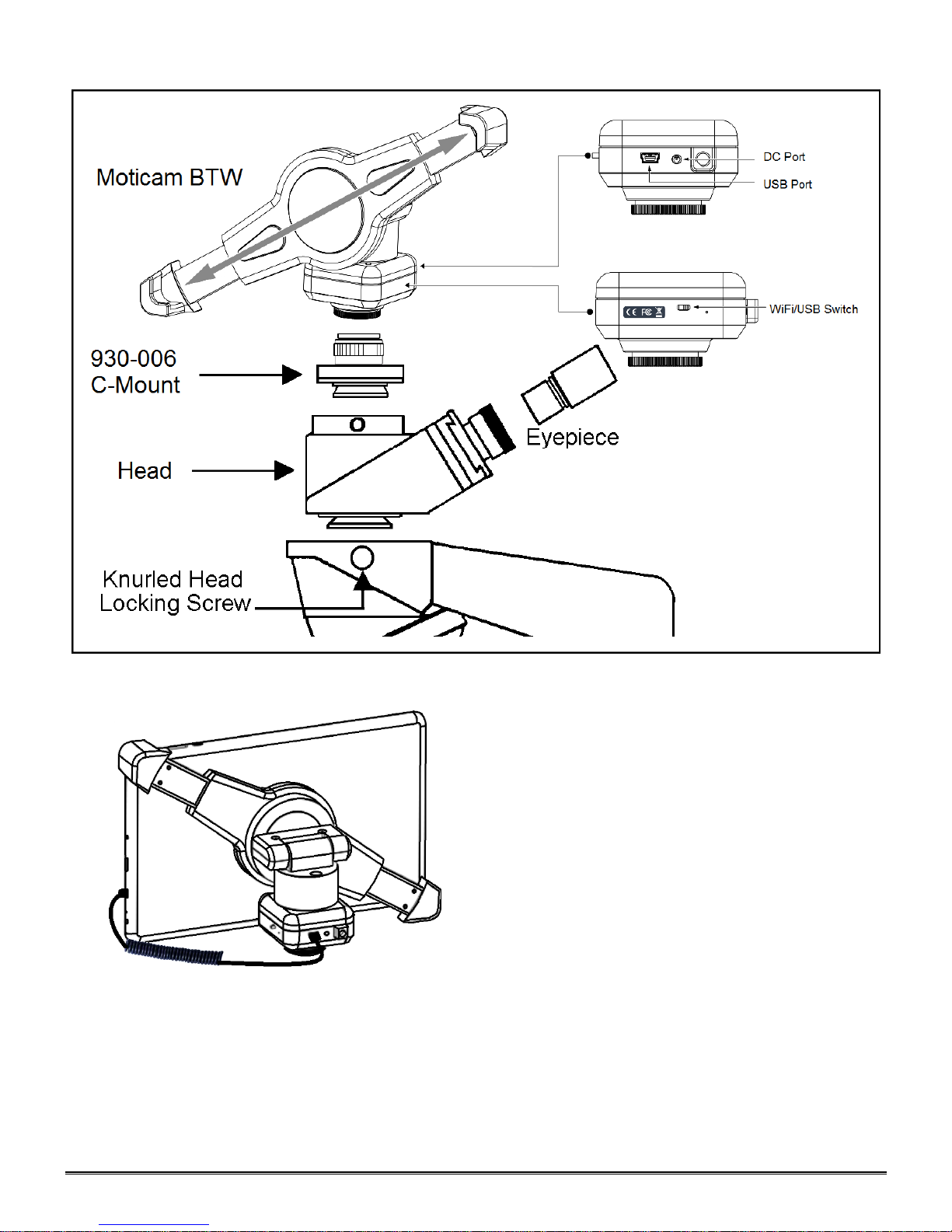
Connecting Tablet to Camera
1. Take the 8” Tablet and mount it into the bracket assembly. The bracket will hold the tablet at opposite corners
of the tablet screen.
2. Taking the spiral USB cable cord and plug one end into your camera and the other into the side of the Tablet
screen. (See picture above)
3. Unless your tablet is fully charged, plug the power adapter into the back of the camera, next to the USB port.
4. This will both charge and allow you to use the camera/tablet at the same time.
5. *Unplugged from the charger, the tablet / camera are able to function for about 2hrs.*
Page 20
20
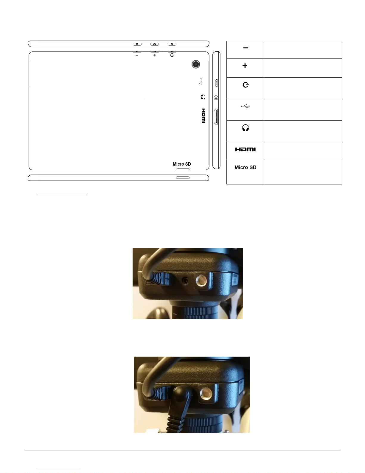
TABLET OPERATION
Volume adjustment - decrease
Volume adjustment - increase
Hold for a few seconds to turn
unit on
Micro USB Port for charging
tablet and connecting to bracket
camera
Provides sound via
earphone/speaker
Connects to HD ready device via
HDMI cable
Micro SD Card Slot for storing
images on Micro SD Card (4GB
included) 32GB Max
POWER MANAGEMENT
Power to the BTW camera is supplied via the coiled USB cable provided with this product. Since the tablet
batteries must supply power for both the tablet and camera simultaneously, approximately 2hrs of continued used
can be expected. 8hrs of recharging is required to replenish the tablet battery. So allowing it to charge overnight is
highly recommended.
1. Camera connected to tablet, supplying power via USB:
If more than two hours of continuous use is required, use the supplied wall charger and power cable included with
your tablet. Leaving the power charger connected to the camera will trickle charge the tablet. This will be a much
slower rate, but should allow time beyond 2hrs.
2. Camera connected to both tablet and wall charger: Trickle charging tablet via USB.
Page 21
21
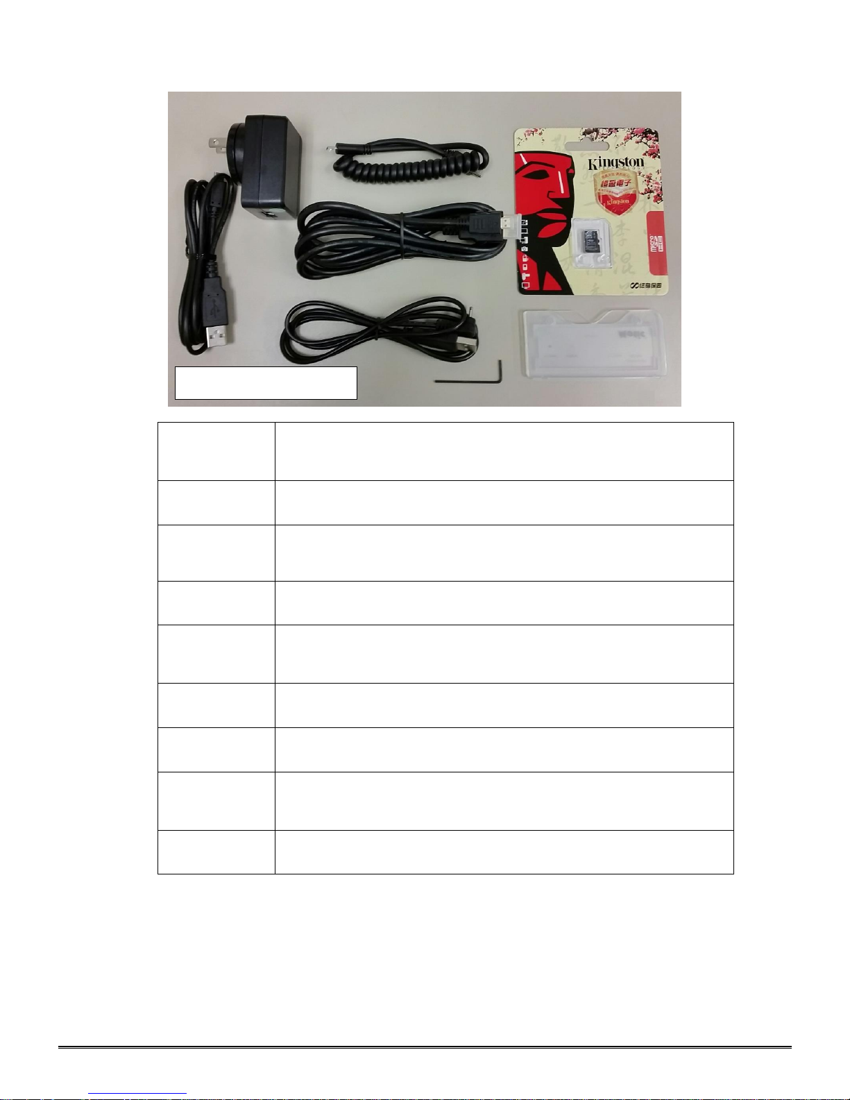
TABLET ACCESSORIES
HDMI Cable
This cable will enable you to connect to an HDMI ready device, to view
your tablet on a larger format. The displayed image will replicate the
displayed image of the tablet.
Power Adapter
This 5V DC power adapter is for charging your tablet’s battery. It is also
used to power the camera in WiFi mode.
Calibration Slide
This slide will enable you to calibrate your tablet to your microscope, for
accurate measurements. You do not need to calibrate your microscope
in order to begin using your table/microscope.
C-Ring
This ring is used between the camera and c-mount to achieve par-focus.
Pre-installed on MA15602 – C-Mount.
4GB Micro-SD
This storage card can be used with your tablet to store images and then
transfer them to your computer. This card is provided as a courtesy
and cannot be replaced. *32GB Max Supported*
Mini USB to
Micro USB
Provides power and feed connection between the tablet and camera.
To operate the camera, move the switch to the camera position.
USB to Micro
USB
This cable when used in conjunction with the power adapter is used to
charge the tablet.
USB to Mini
Power Din
This cable is used to power the camera, in WiFi mode. This cable
can also be used to charge both the tablet and camera at the same
time. Keep plugged into camera at all times, if possible.
L-Wrench
Optional Wrench for mounting bracket to Motic branded trinocular
microscopes
Please Note: Items included may differ
in appearance from items pictured
Page 22
22
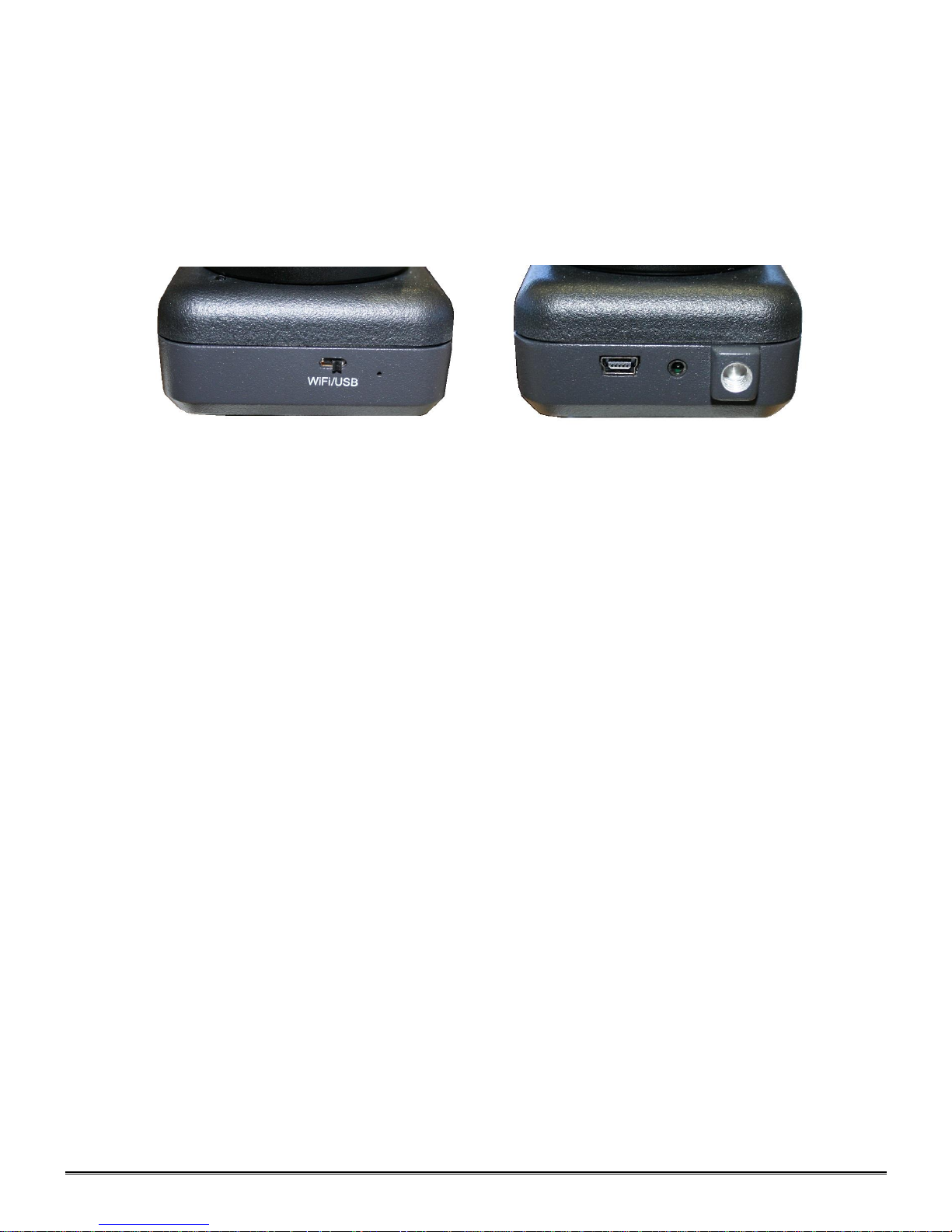
Camera Switches and Ports – Limited Production
Camera Switch
Camera Reset
Camera Power /
WiFi
Mini USB
This feature is limited to a small production batch, not a standard feature of this camera.
When the switch is in USB mode – The camera will only transmit one of two ways. It will transmit to
either the tablet via the supplied coiled USB cable or through an optional A-Male to Mini-B USB 2.0.
(Available to purchase through any electronics supply dealer) Motic Images 3.0 required for the
computer connection. The light on the camera will not turn on in this mode.
When the switch is in WiFi mode – The camera will only transmit out in WiFi. The light on the camera
will turn blue, indicating it is transmitting. The image will not be available on the tablet in this mode.
When placing the switch in the WiFi mode, the power adapter must be connected to the camera. The cable
supplies power to the camera.
Switch on WiFi – No Tablet Connection – Power must be plugged in
Switch on USB – Tablet / Computer* Connection
*Motic Images 3.0 required – see page 21*
Connecting your WiFi enabled device to the BTW camera
1. Download the MotiConnect app from the App Store, Google Play, or Chrome Store.
2. Connect the camera to the power supply.
3. Switch the camera to WiFi transmission mode.
4. Turn on your WiFi enabled device and connect to the SSID provided on the camera: MCX_BTW_XXXX
You will connect to the camera as you would any WiFi router.
5. Default password is always: 12345678
6. Start the MotiConnect application. The connection should be automatic.
7. You can now view the image live on the MotiConnect app as well as capture, measure and annotate the image
using the tools provided.
8. You can connect up to 5 other tablets or other WiFi devices to the BTW signal at the same time in order to
share the live image.
Connecting your WiFi enabled computer to the BTW camera
The BTW camera can also be used with Motic Images Plus software for Windows computers. If you have a WiFi
enabled laptop or computer you can install Motic Images Plus from the CD provided.
1. Connect the camera to the power supply.
2. Switch the WiFi transmission mode.
3. Connect to the SSID provided on the camera: MCX_BTW_XXX - You will connect to the camera as would
any WiFi router.
4. Default password is always: 12345678
5. Start the Motic Images application – Click File – Click Capture
6. The Motic Live Imaging window will open.
7. The Imaging Device box should have the Moticam X selected and you should now have an image.
Page 23
23
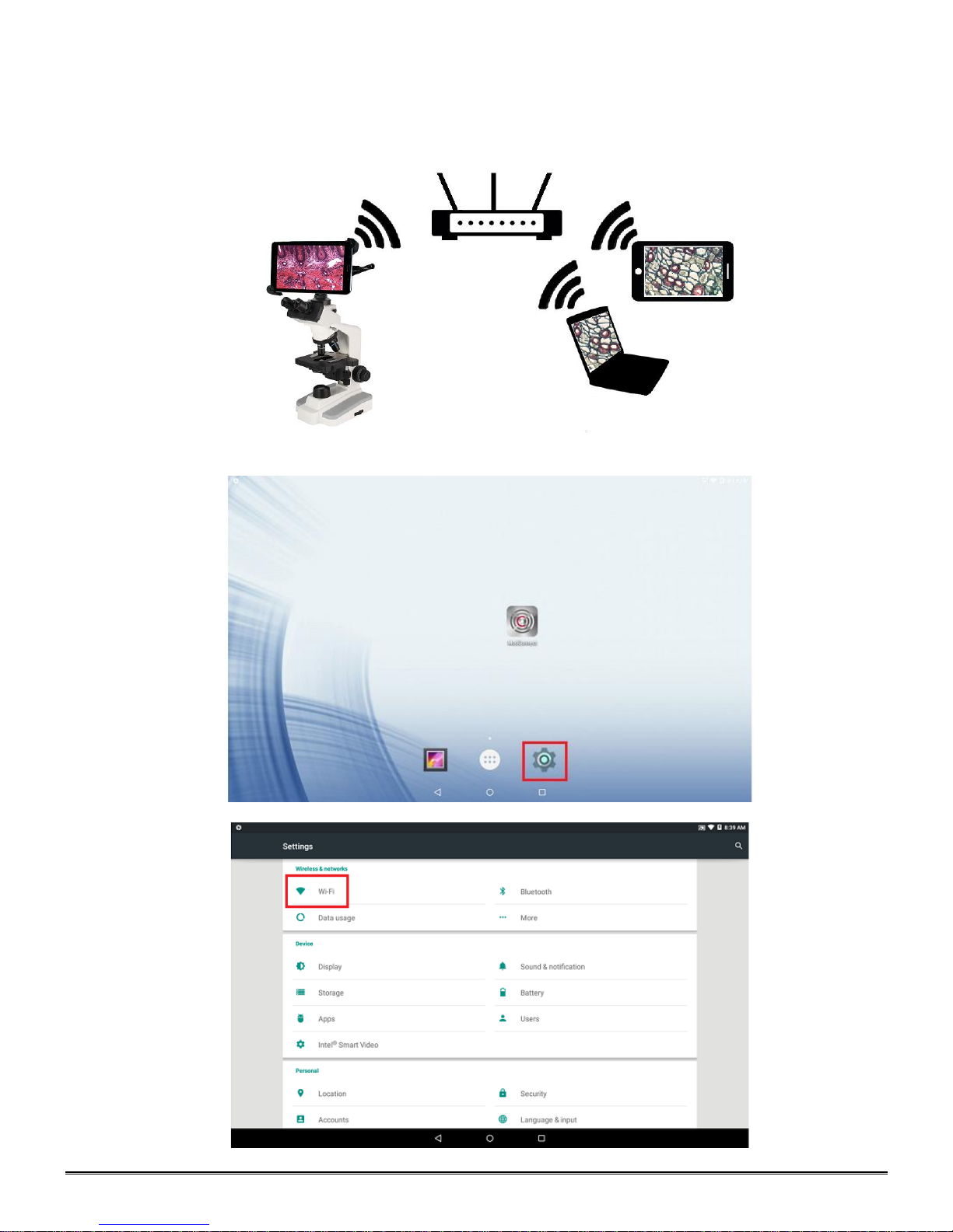
Connecting the 169-BTW1 to your existing network – Advanced
The BTW camera has the unique ability to connect to your existing network system using the MoticHub feature.
1. On the home screen of the tablet select the Settings icon.
2. Select WiFi within the Settings window.
Page 24
24
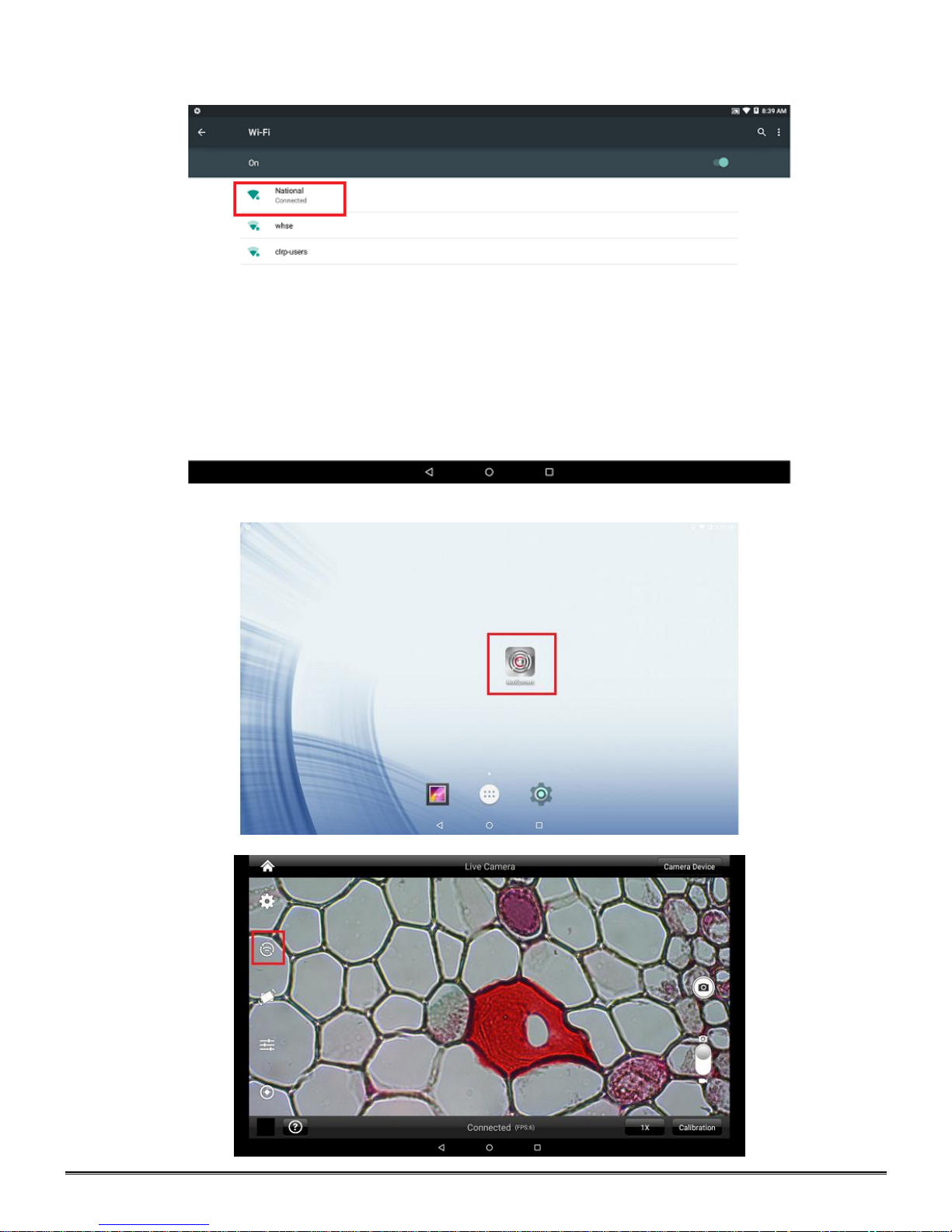
3. Find your Work/Home WiFi SSID and connect. *turn WiFi on if turned off*
Note: In this case I have selected National.
4. Now you have added the tablet to your WiFi network
5. On the home screen of the tablet select the MotiConnect app.
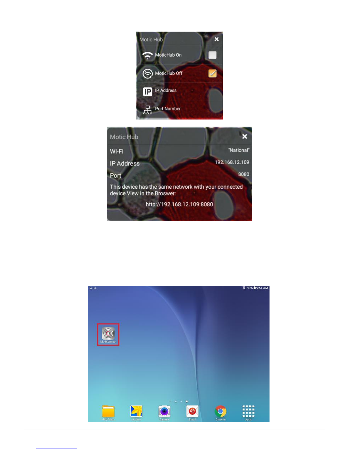
6. Then select the MoticHub icon and MoticHub will launch.
Page 25
25
7. Turn MoticHub On. This must be done every time you wish to broadcast the image.
8. MoticHub will create an IP address for the tablet on your network. This should not change.
9. Write down the generated IP address, you will need this to connect your WiFi enabled
device/tablet/phone/computer/laptop.
10. Now any tablet or computer/laptop connected to your network will have access to your live image.
Connecting to Networked BTW with MotiConnect App
1. Make sure you are first connected to your office/home WiFi network.
2. Download the MotiConnect app from the App Store, Google Play, or Chrome Store, to your android or apple
device/tablet/phone.
3. Start the MotiConnect application.
Page 26
26
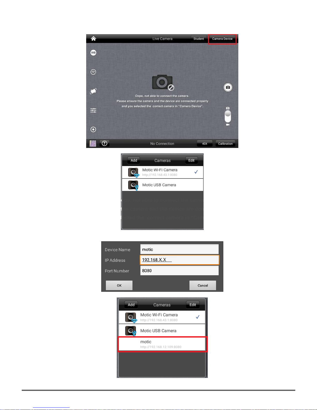
4. Click on the Camera Device button at the top right hand of the screen.
5. Click on the Add button on the pop up window
6. You may give your New Device any name, however the IP Address must be same as the IP generated by
MoticHub.
7. Now select your New Camera
Page 27
27
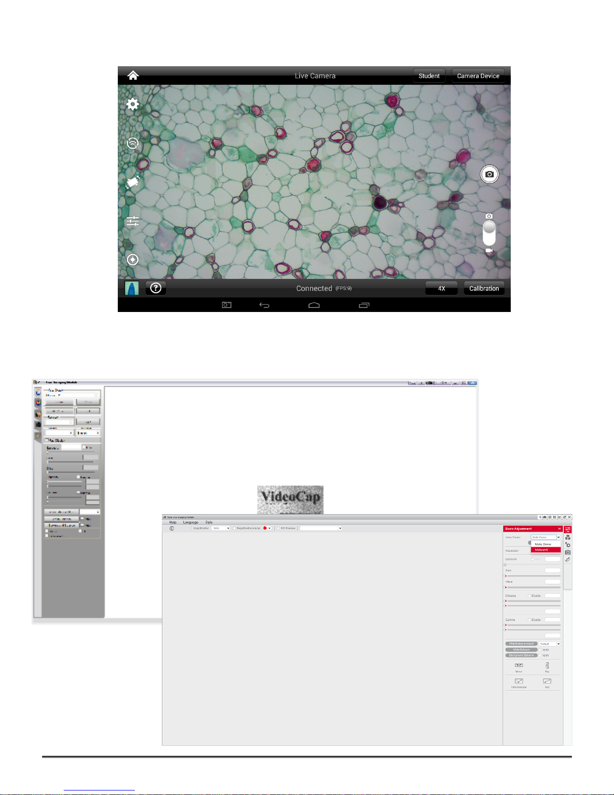
8. You can now view the image live on the MotiConnect app as well as capture, measure and annotate the image
using the tools provided.
Connecting to Networked BTW with Motic Images
1. Install the Motic Images software into your computer or laptop.
2. Start the Motic Images application – Click File – Click Capture
3. The Motic Live Imaging window will open.
Page 28
28
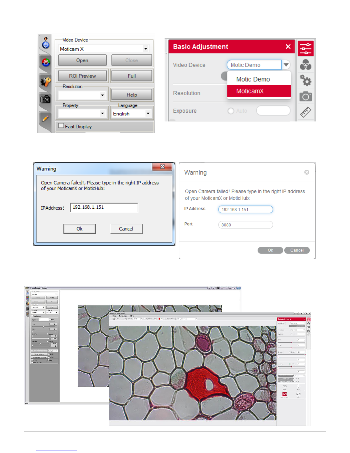
4. The Video Device box should have the Moticam X selected.
5. Click on Open to open the Moticam X IP address box.
6. In the open Moticam X IP address box type in the IP address generated by the MoticHub feature of the BTW tablet.
7. Once you click OK, the image produced by your BTW tablet should appear.
Page 29
29
TABLET SOFTWARE
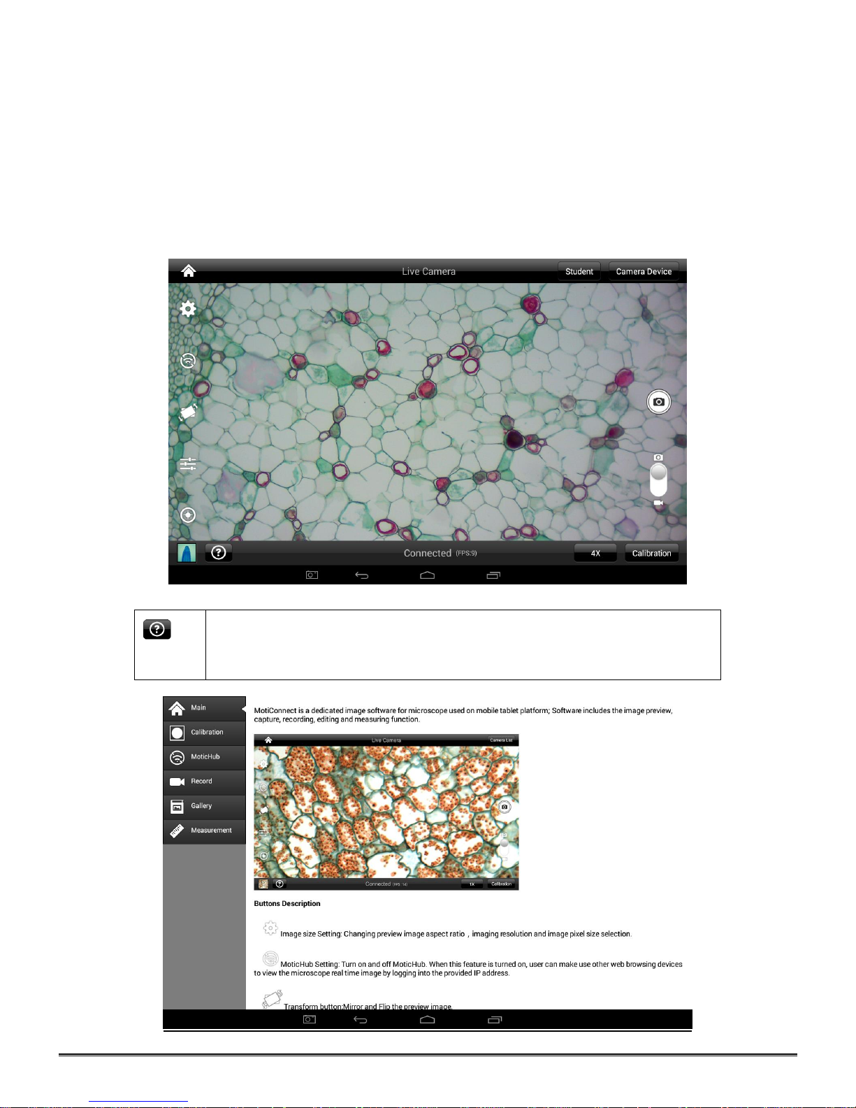
Help Menu - Opens a new window which provides a complete description of all
the features available with the MotiConnect Application
This android tablet comes equipped will all the necessary software needed to start using your equipment out of
the box. Since it is an android tablet, you will be able to connect to your office/school Wi-Fi network to access
the internet and download additional applications. The primary application for accessing your camera is
MotiConnect T.
MOTICONNECT-T OVERVIEW – HELP MENU
MotiConnect is a dedicated image processing Android app for Motic cameras, which includes image preview,
capture, recording, editing and measuring functions. Please refer to the Application Help guide for a complete
description of the MotiConnect Application.
HELP BUTTON
Page 30
30
CALIBRATION
– (*Optional – not necessary to use your microscope*)
To prepare for the calibration process, please make sure you have the calibration slide. The calibration slide
has four individual dark round circles. Each dark round circle corresponds with each objective on your
microscope.
The 1.5mm dot (150um – microns) with the 4X objective.
The 0.6mm (600um – microns) with the 10X objective.
The 0.15mm (150um – microns) with the 40x objective.
The 0.07mm (70um – microns) with the 100X objective.
To begin the calibration process, place the calibration on the stage.
1. First place your calibration slide on the stage, switch to the 4X objective, and move the slide over to the
1.5mm dot.
2. With the dot centered on the tablet screen, select the calibration button, located on the bottom right hand
side of the screen. Select Calibrate the Image.
3. Make the captured image is clean and round. Then click the Calibration button again.
4. You should have a bright green circle on the screen.
5. This time the calibration settings window will open.
6. In the objective magnification window select the objective you captured the dot with. In this case the 4X
objective.
7. In the diameter window select the diameter of the dot you captured. In this case the 150um. Then click
OK.
8. The last window that will open is the Save Calibration window. Since you capture this image with the 4X
objective, it is best to enter this on this line.
9. The objective line should default to the objective you are calibrating. In this case it should say 4X.
10. The X and Y numbers on the next two lines should be near identical. Look at the first three numbers. As
long as they are the same within one or two digits, you have a good calibration.
Click Ok and you are done.
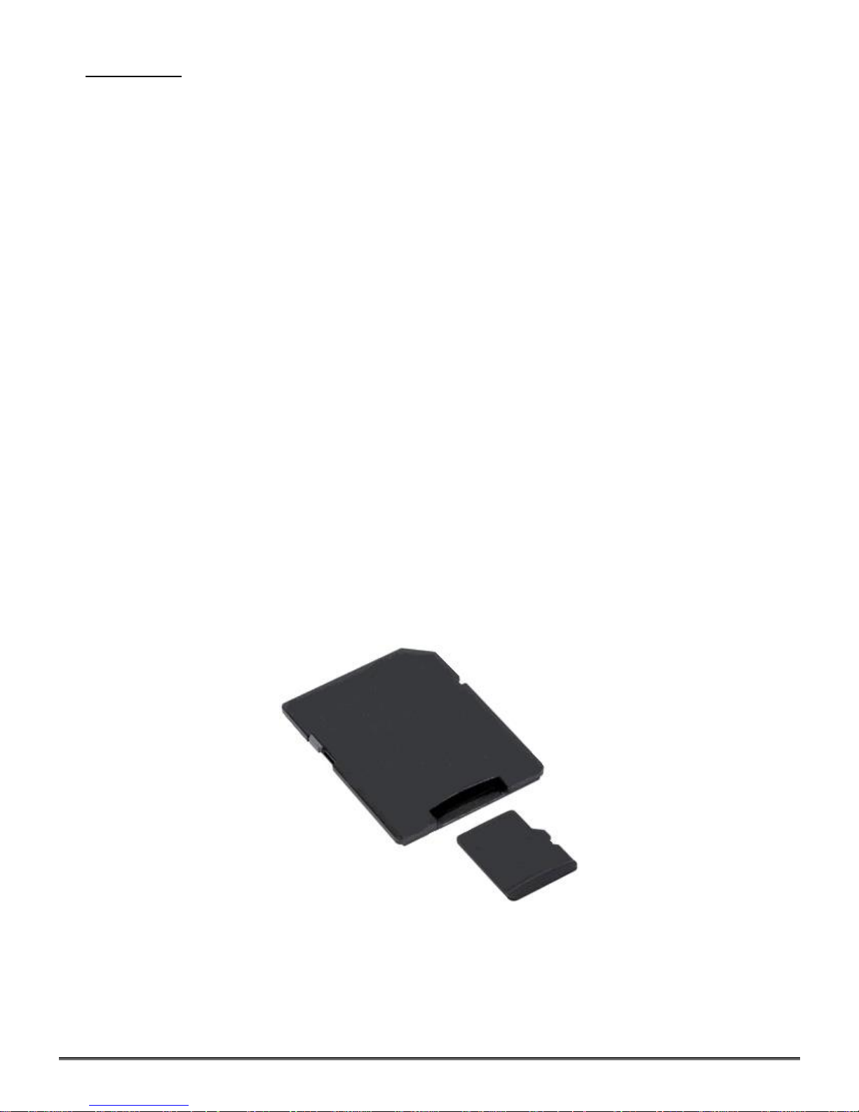
TRANSFERING IMAGES TO YOUR COMPUTER
By default all your images are saved to the Micro SD card included with your M10T-BTW series microscope.
This card is provided as a courtesy. If it is missing or lost, you will need to purchase a replacement. It is highly
recommend that you purchase a Micro SD to Standard SD card adapter.
This is simplest and easiest way to transfer images to your computer. Images are automatically captured as
Jpeg images. If your computer/laptop does not come with an SD card slot, a SD card reader will need to be
purchased as well. *Please note: 32GB Max*
Page 31
31
MOTIC IMAGES 2.0 SOFTWARE
You can use your transfer images with the Motic Images 2.0 software included with microscope to annotate,
save and file your images.
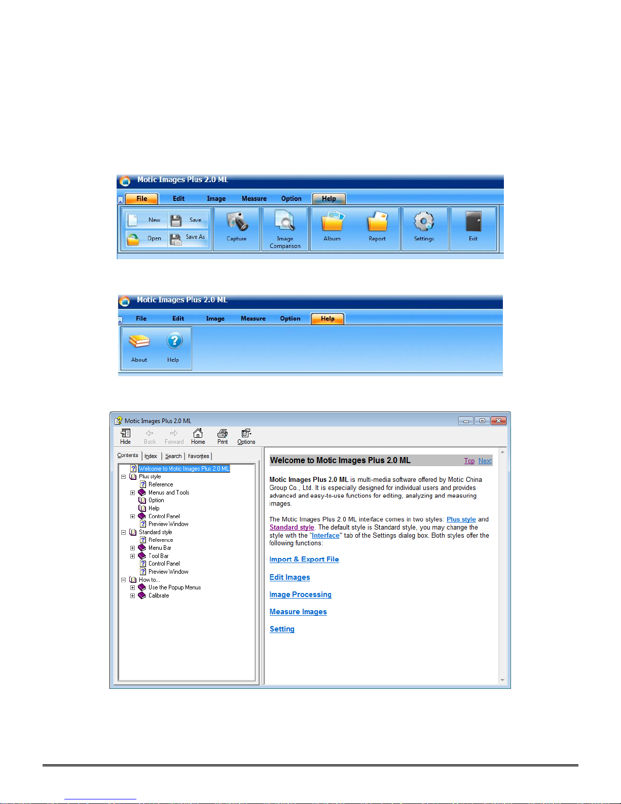
Full Help Menu
The full software manual for Motic Images is accessible within the software’s main page.
To begin, open the Motic Images Software.
At the top of main screen find the menu tab labeled Help:
Click on Help and then select the help option:
This will open the Motic Images help file contents, containing the full help menu:
Page 32
32
Motic Live 2.0 Live Imaging Module
If you are connecting your camera via WiFi to your laptop of WiFi enabled computer, you can use the Motic
Images 2.0 software to view and capture your images.
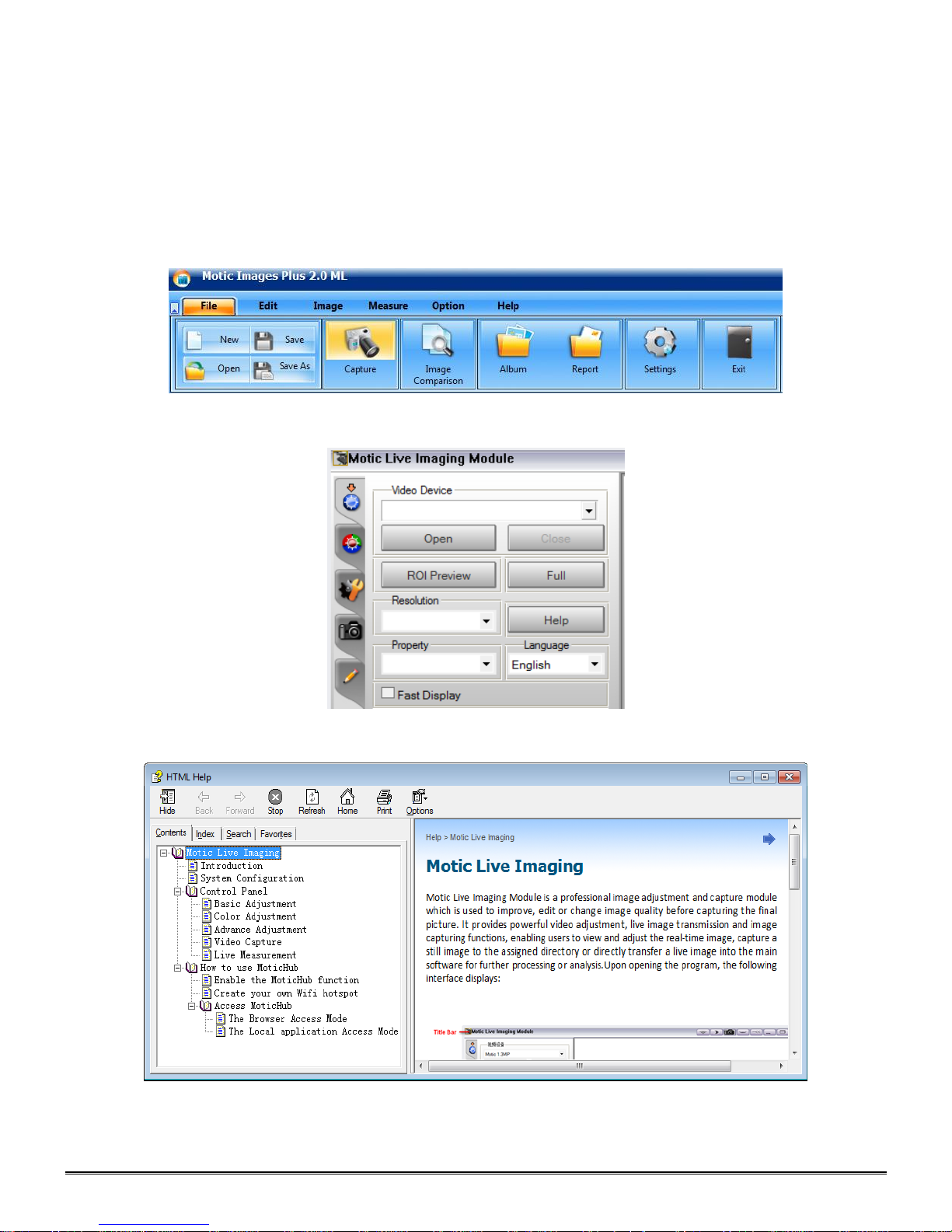
Full Help Menu
The full Live Imaging Module manual is accessible within the live Imaging main page.
To begin, open the Motic Images Software.
At the top of main screen find the menu tab labeled File and click on Capture:
Once the Motic Live Imaging Module has opened, click on Help:
This will open the Motic Live Imaging Module help file, containing the full help menu:
Page 33
33
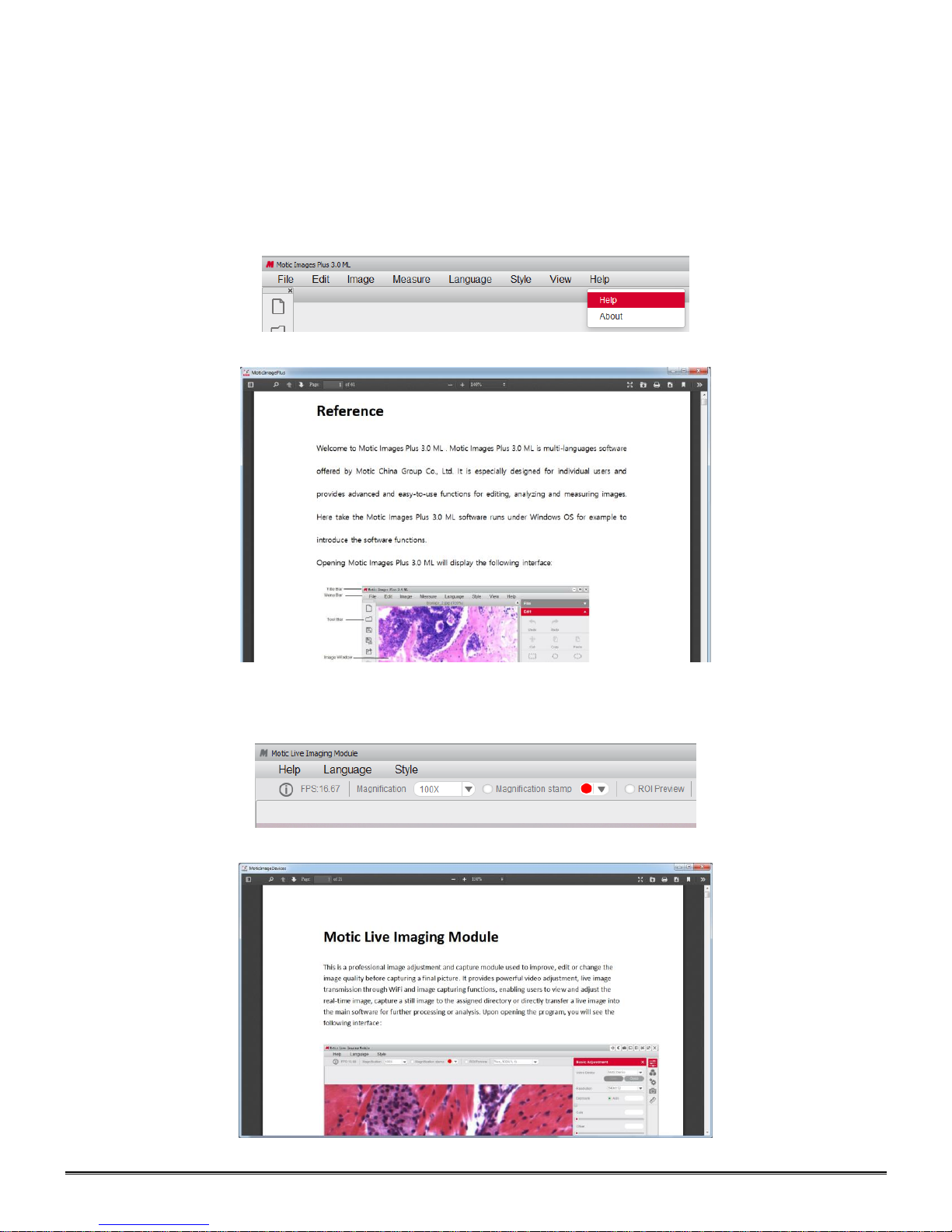
MOTIC IMAGES 3.0 SOFTWARE
The Motic Images 3.0 software, like the Motic Images 2.0 software will allow you to view, capture, annotate and
save your images. For further assistance in using the Motic Images 3.0 software please refer to the Motic Help
files. These files will help explain the functions of software. There are help files for both the main Motic
Images software window, as well as the Motic Images Live Imaging window.
MOTIC IMAGES 3.0 HELP GUIDE
To access the Motic Images 3.0 help menu, click on Help, located at the top of the Motic Images software
screen.
Once the Help window open you will find the help guide within.
Motic Live Imaging Module Help
To access the Motic Images Live Imaging help menu, click on Help located at the top left hand side of the
screen.
Once the Help window open you will find the help guide within.
Page 34
34
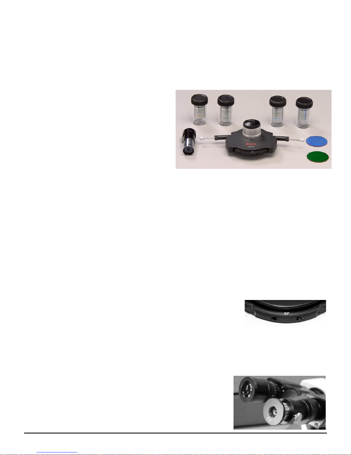
MODEL 926 PHASE CONTRAST SET
INTRODUCTION
Phase contrast microscopy provides a means to observe transparent specimens, which are very difficult to observe
under bright field illumination. Another advantage of phase microscopy is that it allows the user to observe living
specimens that are usually destroyed by staining or fixing reagents. The phase turret control has five positions; one for
standard brightfield illumination and four different annuli positions for phase contrast illumination.
COMPONENTS
Plan 20X Ph/0.40 phase din objective.
Plan 40X Ph/0.65 phase din objective.
Plan 100X Ph/1.25 phase din objective.
Five position 1.25NA Phase turret condenser.
Centering telescoping eyepiece
Green filter, 45mm diameter
ASSEMBLY
A. Install phase turret condenser
B. Install filter
C. Install objectives
OPERATION
A. Rotate condenser focusing control knob to move phase turret condenser to the top of its travel.
B. Rotate phase turret annuli control until the letters BF (brightfield) can be seen at
C. Rotate revolving nosepiece to position 10X Ph/0.25 phase objective into optical path.
D. Place a standard specimen slide (cover slip up) on top of stage surface.
E. Adjust microscope focus controls until specimen is in sharp focus.
F. Remove specimen slide from stage.
G. Remove eyepiece from eyepiece tube, if binocular version remove one of the two eyepieces.
H. Install centering telescope eyepiece into eyepiece tube.
I. Loosen knurled locking screw located on side of centering telescope
J. Hold knurled locking screw with one hand, grasp very top of centering
Plan 10X Ph/0.25 phase din objective.
Blue filter, 45mm diameter
1. Rotate coarse focusing knob to move microscope state platform to its highest position.
2. Loosen knurled locking screw located on the side of microscope condenser mounting ring.
3. Insert the phase turret condenser sleeve into condenser mounting ring.
4. Tighten the knurled locking screw to secure phase turret condenser.
1. Insert filter into filter recess located at top of illuminator lighthouse condenser lens.
a. Blue filter is utilized for bright field observation.
b. Green filter is utilized for phase observation.
1. Rotate coarse focusing knob to move microscope stage platform to its highest position.
2. Remove objective dust caps from the revolving nosepiece.
3. Screw objective lenses into nosepiece, making certain to mount them in consecutive order, 10x, 20x, 40x,
and 100x.
front of phase turret condenser assembly. BF opening must click into locked
position to insure proper centering.
eyepiece.
telescope eyepiece with other hand, peer through eyepiece while sliding
sleeve up until the phase ring in the objective is in focus (sleeve is
approximately 1” up from knurled locking screw).
Page 35
35
K. Tighten eyepiece knurled locking screw.
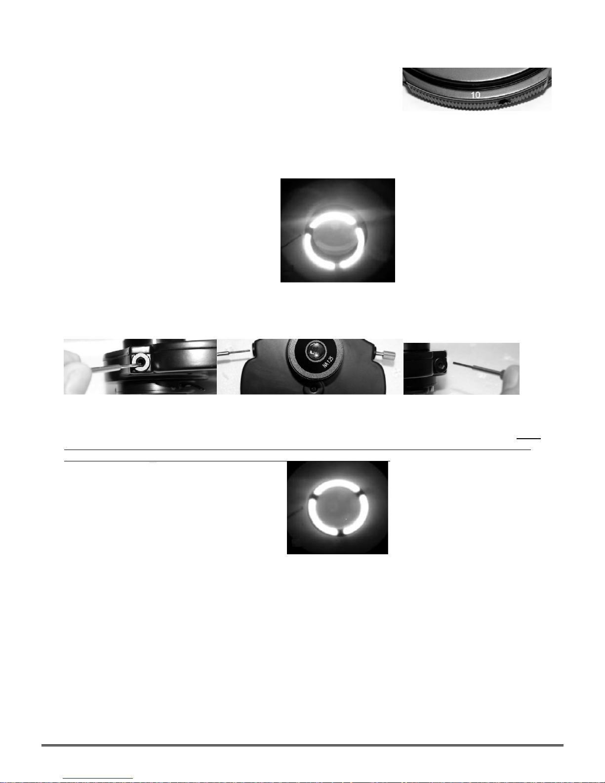
L. Rotate the phase turret annuli control until the number 10 can be seen at
front of phase turret condenser assembly. Annuli must click into position to
assure proper centering.
M. Using condenser focusing control knob, focus the bright annuli ring located
in phase turret annulus condenser.
N. Observe the two rings in the field of view.
1. The dark larger annulus ring is located in the objective lens
2. The bright smaller annulus is located in the phase turret condenser.
O. Centering of the annuli:
P. Depress the two knurled head centering screws that extend out from each side of phase turret condenser
assembly until they engage the hex socket screws of annuli centering
mechanism.
Q. While keeping the two centering screws depressed, look through the centering telescope and observe rings
located in objective and phase turret condenser. Rotate the centering screws in or out, moving image of the
smaller bright annulus ring annuli located in phase turret condenser until it is centered to the larger dark annulus
located in the objective. Both rings must be concentric to each other to achieve maximum performance. Make
sure that the knurled head centering screws are disengaged from the hex socket screws of annuli centering
mechanism and in the “out” position before rotating phase turret condenser.
R. Repeat above steps with the 20x, 40x and 100x phase objectives, making sure to position the corresponding
annuli of phase turret condenser to matching objective indexed in optical path. (Plan 10Ph/0.25 matched to the
number 10 on rotating phase turret condenser.)
S. It will be necessary to focus the telescoping eyepiece and phase turret condenser with each objective lens.
T. When you have adjusted all 4 annuli to their respective objective lenses remove centering telescope from
eyepiece tube and install eyepiece.
1. Microscope is now ready for use.
2. The phase objectives will work well as standard bright field objective lenses. To view in bright field simply
position the O position to the front of condenser turret and adjust condenser and iris diaphragm for standard
use.
Page 36
36
CLEANING YOUR MICROSCOPE
Dirty
Clean
National microscopes are designed to function with minimal maintenance, but certain components should be
cleaned frequently to ensure ease of viewing. The power switch should be turned off or the microscope should
be unplugged when not in use.
Do not disassemble your microscope
Disassembly may significantly affect the performance of the instrument, and may result in electric shock or
injury and will void the terms of the warranty.
Never attempt to dismantle any parts other than the ones described below. If you notice any malfunction,
contact your nearest National Optical supplier.
Optics
Keeping the optics of your microscope clean is essential for obtaining clear images.
Choosing the best cleaning method depends on the nature of the optical surface and type of dirt.
Dirtiness on the image may be caused by the following
variables:
Dirt on the outer or inner eyepiece lens.
Dirt on the front lens of the objective.
Dirt on the upper lens of the condenser.
Dirt on the surface of the sample slide glass.
Dirt on the upper lens of illuminator.
Dirt on other optical components of the microscope such
as mirrors, lamps, filters, intermediate lenses …
In the case of microscopes with a camera attached to it:
Dirt on the camera adapter.
Dirt on the protection filter of the camera sensor.
For Eyepieces with reticules:
Dirt on the outer or inner reticle glass.
Objectives are the optical component of the microscope that
require the most maintenance. Because for their actual use,
they can get dirty easily.
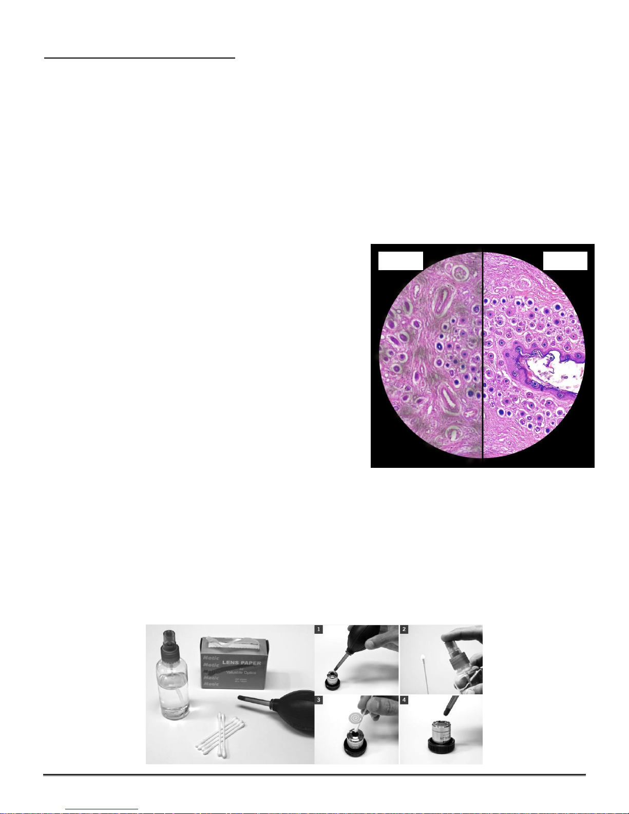
For objectives that work without oil (dry): The first step is to carefully unscrew the objective from the nosepiece.
In order to make things easier and safer, screw the objective onto one of the objective cases supplied with
microscope. By doing it this way, the objective will be in a stable position avoiding possible falls.
(1) Proceed by cleaning it using pressurized dry air - or an air gun if available – and, if after this is done we still
observe spots of dust or dirt, (2) Clean with a cotton swab dampened with a low graduation of alcohol 70% or
with a mixture of alcohol and ether (ratio alcohol: 3 to ether: 7). (3) With a spiral movement (starting from the
center of the lens) we will then clean the surface of the lens. (4) Dry its surface by using pressurized dry air
and check that the lens is clean either with the help of a magnifying glass or by screwing the lens back on the
revolving nosepiece of the microscope.
Page 37

37
For objectives that work with immersion oil it is essential to clean them after each observation session. To
clean use a cleaning cloth for lenses slightly dampened with a low graduation of alcohol. Proceed by cleaning
the frontal objective lens (normally 100X-Oil). It is important for those objectives that work at a very close
distance to the sample.
For optical components such as eyepieces, condensers, filters, etc. we recommend using the same
cleaning method. First cleaning it with pressurized dry air, then cleaning it with a cotton swab or a cleaning
cloth for lenses (slightly moistened with a low graduation of alcohol) and finally drying it with pressurized dry air.
Once the cleaning process is finalized if the image is still not clear, you can either contact us or you can contact
your National Optical supplier.
For users that have a digital camera mounted on the microscope and whom observe dirt on the digital
image, it is important that the first step is to proceed with objectives maintenance, as explained above. If the
dirt persist, it must be determined if it is within the microscope or the camera. To check this simply loosen the
adapter and rotate the camera. If the dirt rotates while turning it, then it means that it is in the microscope. If it
does not rotate, then it is either in the adapter or in the protection filter of the sensor. If the dirt is on the surface
lens of the adapter then you can use the same cleaning method that we have explained above, but if the dirt is
in the protection filter of the sensor then use pressurized dry air only. If the dirt persist you can either contact us
or you can contact your National Optical supplier.
Mechanics
The mechanical components of the microscope require less maintenance than the optical components. Our
first maintenance advice is to use the dust cover provided with the microscope, to avoid the accumulation of
dust on the microscope.
To clean the stand or the specimen holder, Use a cleaning cloth moistened with soap diluted in distilled
water. After this proceed drying the entire surface of the microscope. Take special care with the electrical
components of the microscope such as the ON / OFF switch, the dimmer, the lamp holder…
If there are grease stains, use the same cloth moistened with a low graduation of alcohol.
If you face any problems related to the maintenance of your microscope, please contact us. Our technicians
will gladly help you solve your maintenance issue/s.
CLEANING – The front lens of the objectives (particularly the 100XRD) should be cleaned after use. The lens
surface may be gently cleaned with a soft camel hair brush, or blown off with clean, oil-free air to remove dust
particles. Then wipe gently with a soft lens tissue, moistened with optical cleaner (eyeglass or camera lens) or
clean water. Immediately dry with a clean lens paper.
CAUTION - Objectives should never be disassembled by the user. If repairs or internal cleaning should be
necessary, this should only be done by qualified, authorized microscope technician. The eyepiece(s) may be
cleaned in the same manner as the objectives, except in most cases optical cleaner will not be required. In
most instances breathing on the eyepiece to moisten the lens and wiping dry with a clean lens tissue is
sufficient to clean the surface. Lenses should never be wiped while dry as this will scratch or otherwise mar the
surface of the glass.
The finish of the microscope is hard epoxy and is resistant to acids and reagents. Clean this surface with a
damp cloth and mild detergent.
Periodically, the microscope should be disassembled, cleaned and lubricated. This should only be done by a
qualified, authorized microscope technician.
DUST COVER AND STORAGE – All microscopes should be protected from dust by a dust cover when in
storage or not in use. A dust cover is the most cost-effective microscope insurance you can buy. Ensure that
the storage space is tall enough to allow the microscope to be placed into the cabinet or onto a shelf without
making undue contact with the eyepieces. Never store microscopes in cabinets containing chemicals which
may corrode your microscope. Also, be sure that the objectives are placed in the lowest possible position and
the rotating head is turned inward and not protruding from the base. Microscopes with mechanical stages
should be adjusted toward the center of the stage to prevent the moveable arms of the mechanical stage from
being damaged during storage in the cabinet.
Page 38

38
TROUBLESHOOTING
PROBLEM
REASON FOR PROBLEM
SOLUTION
Light fails to operate
Outlet inoperative.
AC power cord not connected.
Lamp burned out.
Fuse burned out.
Fuse burns out too soon.
Fuse blows instantly when replaced.
Incorrect lamp used improper voltage
or base.
Have qualified service technician repair outlet
Plug into outlet.
Replace lamp.
Replace fuse.
Replace with proper fuse (Time delay).
Unit has short, have qualified technician repair
electrical short.
Replace with specified lamp.
Light burns out too soon
The voltage is too high.
Adjust intensity control to the minimum
position before turning the power switch on.
Light bulb burns out
immediately
Incorrect lamp used.
Use proper lamp (12 volt 20 watt).
Plug unit into proper outlet 120v or 220v
Light flickers
Lamp not properly inserted into socket.
Lamp about to burn out.
Fuse holder not locked into proper
position.
Loose connection at AC outlet.
Properly insert lamp.
Replace lamp.
Properly install fuse holder.
Have qualified service technician repair outlet.
PROBLEM
REASON FOR PROBLEM
SOLUTION
No image.
Nosepiece not indexed properly.
Light too bright
Move revolving nosepiece until objective lens
clicks into position.
Adjust light intensity control to a lower
position.
Poor resolution.
(Image not sharp)
Objective lens dirty.
Eyepiece lens dirty.
Slide upside down.
Cover slip on specimen slides too
thick.
Too much light.
Condenser lens dirty.
Rack stop not set a proper position.
Clean objective lens.
Clean eyepiece lens.
Turn specimen slide over (cover slip facing
up).
Use 0.17mm thick cover slip.
Adjust light intensity control to a lower
position.
Iris diaphragm not properly adjusted.
Clean condenser lens.
Adjust rack stop.
Spots in field of view.
Eyepiece dirty.
Specimen slide dirty.
Condenser lens dirty.
Clean eyepiece lenses.
Clean slide.
Clean lens of condenser.
Uneven illumination of
field.
Nosepiece not properly indexed.
Diaphragm not properly indexed.
Revolve nosepiece into positive index stop.
Adjust iris diaphragm to proper level.
PROBLEM
REASON FOR PROBLEM
SOLUTION
Does not stay in focus.
Stage drops down
Adjust tension adjustment knob.
ELECTRICAL
IMAGE QUALITY
MECHANICAL PROBLEM
Page 39

39
OPTIONAL ACCESSORIES AND PARTS:
#610-160 WF10X Eyepiece
#610-160R WF10X eyepiece w/reticle, 10mm/100div.
#704-160SP DIN 4X objective lens, 0.10 N.A.
#710-160SP DIN 10X objective lens, 0.25 N.A.
#740-160SP DIN 40X objective lens, 0.65 N.A.
#799-160SP DIN 100X objective lens, 1.25 N.A.
#704-160ASC DIN 4X Super High Contrast objective lens, 0.10 N.A.
#710-160ASC DIN 10X Super High Contrast objective lens, 0.25 N.A.
#740-160ASC DIN 40X Super High Contrast objective lens, 0.65 N.A.
#799-160ASC DIN 100X Super High Contrast objective lens, 1.25 N.A.
#704-160P DIN 4X Plan objective lens, 0.10 N.A.
#710-160P DIN 10X Plan objective lens, 025 N.A.
#740-160P DIN 40X Plan objective lens, 0.65 N.A.
#760-160P DIN 60X Plan objective lens, 0.90 N.A.
#799-160P DIN 100X Plan objective lens, 1.25 N.A.
#800-500 BULB ASSEMBLY, 3W LED
#926 Phase contrast set: Centering telescope, PLAN/Phase 10x, 20x, 40x, 100xR (oil immersion)
objectives, Phase turret condenser assembly including one brightfield position, blue & green filters,
storage case
#965-160 Eyepiece reticle, 10mm/100 div.
#975-002 Carrying case, anodized aluminum, fabric lining, accessory pockets, Velcro straps, keyed lock
(Note: Will not accommodate microscope with camera attached)
#D-905 Power Supply Converter (100-240V 47-63 Hz IN 12V, 2AMP OUT) with power cord
LIMITED LIFETIME WARRANTY
Please see our website, www.nationaloptical.com, for complete warranty details and exclusions.
800-942-0528
www.microscopeworld.com
(Revised 11/04/2016)
 Loading...