

National 160 Instructions Manual
National Optical & Scientific Instruments Inc.
Phone (210) 590-9010 Fax (210) 590-1104
COMPOUND BIOLOGICAL MICROSCOPES
Copyright © 1/2/01
National Optical & Sc i ent i fic Instrument I nc.
11113 Landmark 35 Drive
San Antonio, Texas 78233
INSTRUCTIONS FOR
160 SERIES
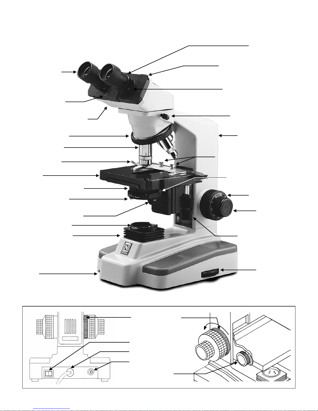
Models 160 (monocular head), 161 (dual head), 162 (binocular head), 163 (trinocular head), all have the same stand
Sliding interpupillary adjustment,
Mark on side of eyepiece tube for
Knurled head locking screw
Arm of microscope stand
Two knurled locking screws for
Light intensity
Knobs controlling X and Y
Coarse focus knob
Base
Abbe condenser locking screw
Objective lenses
Viewing head of microscope
Widefield 10x/18
Specimen holder
Stage
Abbe condenser 1.25 N.A.
Iris diaphragm lever
Filter holder for 32mm filter
ON/OFF switch
AC line cord
Fuse
Control knob for
Tension adjustment
Recess for 45mm filter
and stand features…only the head portion differs…illustrated is Model 162.
Knurled diopter ring
grips located on both left and right
side of diopter scale
eyepiece
indexing diopter reading
Interpupillary scale
Revolving nosepiece
(mechanical stage)
Illuminator condenser
securing specimen holder to stage
Fine focus knob
movement of mechanical
stage
control knob
knob
Abbe condenser
3
INTRODUCTION
Thank you for your purchase of a National m icroscope. It is a well built, precision instrument carefully checked to
assure that it reaches you in good condition. It is designed for ease of operation and years of carefree use. The
information in this manual probably far exceeds what you will need to know in order to operate and maintain your
microscope. However, is provided to answer questions which might arise, and to help you avoid any maintenance
expense that may be unnecessary.
Your new compound micros cope is a high performanc e microscope with high quality Achromatic objec tive lenses that
provide good resolution and optical centering. The microscope is designed with a built-in ball bearing mechanical stage
providing a travel range of 75mm x 50mm in the X and Y direction with graduation reading up to 0.1mm for acc urate
positioning of specim en. Also included is a ball bearing quadruple nosepiece, pr ecision coaxial focus ing mechanism ,
rack and pinion mounted N.A. 1.25 Abbe condenser and built-in 12 volt 20 watt halogen variable light source.
Carefully read these instructions before operating m icroscope. They will permit you to use your new microscope to its
fullest capability. Nomenclature used to describe components and controls is identified by referring to diagram on page
2.
I. UNPACKING
The microscope and accessories have been carefully packed to assure they reach you in the best possible
condition. Do not discard packing container or m aterials until all components are accounted for. Save pack ing
container in case microscope needs transporting to another location or shipped for repairs. Components are
packed within containers as indicated below.
160 Monocular: (A) Stand
(B) Head, one eyepiece, one rubber eyeshield, four objectives, condenser,
specimen holder, 32m m blue, yellow and green filters, 45mm neutr al filter, spare
fuse, dust cover.
161 Dual head: (A) Stand
(B) Head, vertical viewing eyepiece tube, two ey epieces, two rubber eyeshields, four
objectives, condenser, specimen holder, 32mm blue, yellow and green filters,
45mm neutral filter, spare fuse, dust cover, 2mm “L” type key wrench.
162 Binocular head (A) Stand
(B) Head, two eyepieces, two rubber eyeshields, four objectives, condenser,
specimen holder, 32m m blue, yellow and green filters, 45mm neutr al filter, spare
fuse, dust cover.
163 Trinocular head (A) Stand
(B) Head, two rubber eyeshields.
(C) Vertical viewing eyepiece tube, condenser, specim en holder, 32mm blue, yellow
and green filters, 45mm neutral filter, spare fuse, dust cover.
(D) Three eyepieces, four objectives.
A. Lay container (A) flat and carefully remove microscope stand.
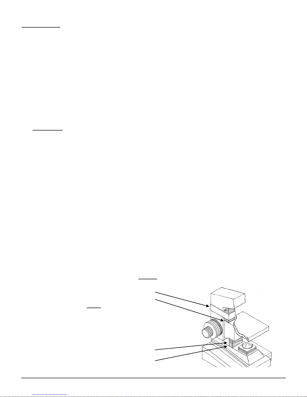
NOTICE
To protect focus mechanism during
shipment, two black plastic wedges (b) (a)
and one black plastic block (c) are (c)
inserted at strategic points as indicated.
These plastic parts MUST
to operating microscope. Failure to do so
will result in damage to focusing mechanism
and will void your warranty.
1. Remove two black velcro straps (a).
2. Remove wedge (b) by pulling apart the
two parts of wedge in opposite directions. (b)
3. Lower stage by rotating coarse focus
knob, on side of microscope illustrated, (a)
in counter-clockwise direction
be removed prior
4
4. Remove block (c) from stand.
5. These components should be retained with styrofoam container
B. Carefully remove from the stand all tape and packing material used to protect microscope components during
shipment.
C. For models 160, 161 and 162, lay container (B) flat and carefully remove head, eyepieces, rubber eyeshields,
vertical eyepiece tube (model 161 only), four objectives, condenser, specim en holder, filters, fuse and dust
cover. For Model 163 trinocular only, lay container (B) flat and carefully remove head, rubber eyeshields,
container (C) vertical viewing eyepiece tube, condenser, specimen holder, filters, fuse and dust cover,
container (D) eyepieces and objectives.
D. Unwrap components, m aking certain that lens surfaces do not come in c ontact with dust, dirt, fingerprints.
Damage to optical surfaces can result from such contaminants, and reduce image quality.
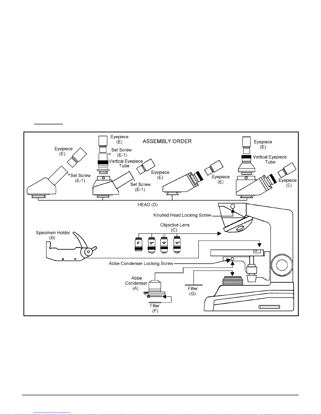
II. ASSEMBLY
A. Condenser: Rotate focusing knob to move stage platform to its highest position. Loosen the Abbe
condenser locking screw and insert Abbe condenser into the mounting ring. Tighten locking screw.
B. Specimen holder: Rotate coarse focusing knob to move stage platform to its lowest pos ition. Remove two
knurled screws from m echanic al stage platfor m . Place s pecim en holder on stage and, using the two knur led
locking screws, attach holder to mechanical stage.
C. Objectives: With stage platform loc ated at its lowest position. Remove the black objective plugs from the
nosepiece, screw all the objectives into the nosepiece, making c ertain to mount them in consecutive order
4x, 10x, 40x, 100x.
 Loading...