

National 158-LED Instructions Manual

National Optical & Scientific Instruments Inc.
Phone (210) 590-9010 Fax (210) 590-1104
Copyright © 11/09/04
National Optical & Sc i ent i fic Instrument I nc.
11113 Landmark 35 Drive
San Antonio, Texas 78233
INSTRUCTIONS FOR
MODEL 158-LED
COMPOUND MICROSCOPES
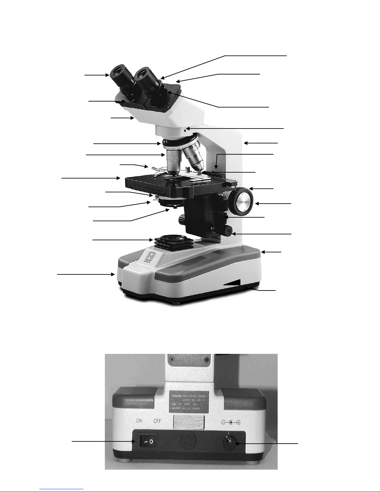
Base
Illuminator condenser
Iris diaphragm lever
Swing-out filter holder
Abbe condenser 1.25 N.A.
Revolving nosepiece
Objective lenses
Specimen holder
Viewing head of microscope
Interpupillary scale
Widefield 10x/18
Knurled diopter rings
Sliding interpupillary adjustment,
Mark on side of eyepiece tube
Head locking screw
Arm of microscope stand
Knobs controlling X and Y
Coarse focus knob
Fine focus knob
Power on/off switch
Tension adjustment collar
Rack stop adjustment screw
Knurled locking screws for securing
Recharging socket
(left & right sides)
eyepiece
Stage
grips located on both left and right
side of diopter scale
for indexing diopter reading
(mechanical stage)
specimen holder to stage
(behind focus knob on left side)
movement of mechanical stage
On/Off switch
Light intensity control knob

INTRODUCTION
Thank you for your purchase of a National microscope. It is a precision instrument carefully checked to assure that it reaches
you in good condition. It is designed for ease of operation and years of carefree use. The information in this manual probably
far exceeds what you will need to know in order to operate and maintain your microscope. However, is provided to answer
questions that might arise, and to help you avoid any maintenance expense that may be unnecessary.
Your new compound microscope is a high performance microscope with high quality achromatic objective lenses that provide
good resolution and optical centering. The microscope is designed with a built-in mechanical stage providing a travel range of
75mm x 30mm in the X and Y direction with graduation reading up to 0.1mm for accurate positioning of specimen. Also
included is a ball bearing quadruple nosepiece, separate coarse and fine focusing, spiral mounted N.A. 1.25 Abbe condenser,
and built-in heat free LED illumination equal to a 20 watt bulb.
Carefully read these instructions before operating microscope. They will permit you to use your new microscope to its fullest
capability. Referring to diagram on page 2 identifies nomenclature used to describe components and controls.
UNPACKING
1. The microscope and accessories have been carefully packed to assure that they reach you in the best possible condition.
Check package containers to make sure all components are accounted for.
a. Microscope stand with the following components already installed WF10x eyepieces (pair), 4 objectives, condenser,
and three rechargeable batteries.
b. Two rubber eyeshields, specimen holder, recharger, dust cover, 0.9mm “L” type key wrench (for lamp replacement),
and 2mm “L” type key wrench (for rack stop adjustment), and instruction manual.
2. Save packing container in case it becomes necessary to ship the microscope for any reason, repack in the styrofoam
container, and then pack the styrofoam in other corrugated shipping container for optimum protection. Use of the
styrofoam alone will not provide adequate protection in transit, and will void your warranty.
DESCRIPTION OF COMPONENTS
1. EYEPIECE (ocular lens): Lens closest to the eye, magnifies the primary image formed by the objective lens. One
eyepiece is equipped with a “ pointer” that rotates as the eyepiece is turned.
2. OBJECTIVE TURRET (nosepiece): Revolving turret which holds objective lenses, permits changes of magnification by
rotating different powered objective lenses into optical path. Reverse position permits easier access to stage when
positioning specimen slides.
3. OBJECTIVE LENS: Lens closest to the object being viewed, forms first magnified image of the specimen.
4. MECHANICAL STAGE: Permits precise, mechanical manipulation of the specimen slide.
5. SPECIMEN HOLDER: Holds specimen slide.
6. STAGE: Platform of the microscope where the specimen slide is placed.
7. CONDENSER: A focusable 1.25 N.A. Abbe condenser lens positioned under center of stage condenses light rays from
substage illumination and fills the back lens element of objective lens to improve image resolution.
8. IRIS DIAPHRAGM: Attached to bottom of Abbe condenser, controls aperture of light by moving control lever left or right.
9. FILTER HOLDER: Attached to bottom of iris diaphragm with swing out built in neutral filter. Swing out filter should be
removed from optical path when using 40x or 100x objective lens.
10. SAFETY RACK STOP: When properly adjusted, controls maximum upward travel of stage. Prevents higher power
objectives from breaking specimen slides, prevents damage to objective lenses. This stop has been pre-adjusted at the
factory.
11. FOCUSING KNOBS: Coarse focusing knobs (larger knobs) located on each side of arm, raise or lower stage to bring
specimen image into focus. Fine focus knobs (smaller knobs located just below coarse focusing knobs) permit more
precise image adjustment.
12. ILLUMINATION: Built-in substage LED illuminator provides constant, reliable pre-focused illumination.
3
 Loading...