

National 111 Instructions Manual

National Optical & Scientific Instruments Inc.
6508 Tri-County Parkway
Schertz, Texas 78154
Phone (210) 590-9010 Fax (210) 590-1104
INSTRUCTIONS FOR
MODEL 111
COMPOUND MICROSCOPE
Copyright © 1/2/01
National Optical & Sc i ent i fic Instruments, Inc.
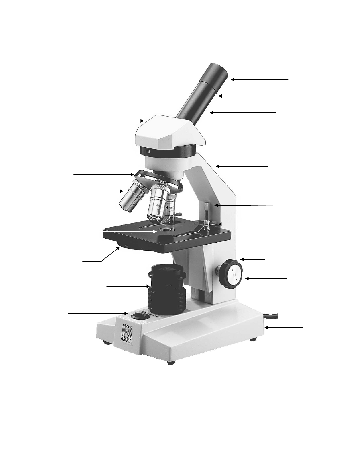
Eyepiece
Eyepiece tube
Arm of microscope
Focus knob
Tension adjustment
(behind focus knob)
Microscope head
Objective turret
Objective lens
Stage clip
Safety Rack Stop
Base
Condenser lens
Disc diaphragm
Eyepiece locking set screw
(located in center of stage)
Illuminator field lens housing

INTRODUCTION
Thank you for your purchase of a National microscope, It is a well built, precision instrument and
carefully checked to assure that it reaches you in good condition. It is designed for ease of operation and
years of carefree use. The information in this manual probably far exceeds what you will need to know in
order to operate and maintain your microscope. However, it is provided to answer questions which might
arise, and to help you avoid any maintenance expense that may be unnecessary.
Carefully read instructions before operating microscope. Nomenclature used to describe components and
controls are identified on opposite page of the manual.
UNPACKING THE MICROSCOPE
Do not discard Styrofoam container or packing materials. Save in case instrument needs to be
transported or shipped for repairs. Remove microscope and dustcover from container. Remove all tape
and packing material used to protect microscope during shipment. Make certain lens surfaces do not
come in contact with dirt, fingerprints or oil. Damage of lens surfaces occurs when they come in contact
with such contaminants, and image quality is reduced.
DESCRIPTION OF COMPONENTS
1. EYEPIECE LENS (ocular lens): Lens closest to the eye, magnifies the primary image formed by the
objective lens. A pointer is located in field of view, and revolves by turning the eyepiece. Use the
pointer to direct attention to specific things of interest on the specimen slide.
2. OBJECTIVE LENS: Lens closest to the specimen, forms the first magnified image of the specimen.
3. OBJECTIVE TURRET (nosepiece): Revolving turret designed to hold objective lenses, permits
changes of magnification by rotating different powered objective lenses into optical path.
4. STAGE CLIPS: Two locked-on clips hold specimen slide in place on stage.
5. STAGE: Platform of the microscope where the specimen slide is placed.
6. CONDENSER LENS: Built-in 0.65 N. A. condenser lens condenses light rays from substage
illumination and fills the back lens element of the objective lens for optimum resolution.
7. DISC DIAPHRAGM: Rotating disc located below stage, with 5 holes of various apertures, designed to
help achieve optimum resolution of the objective lens. Smaller apertures used for lower
magnifications and larger apertures used for higher magnifications.
8. SAFETY RACK STOP: When properly adjusted, controls maximum upward travel of stage while
focusing, prevents higher power objectives from breaking specimen slides, prevents damage to
objective lenses. This safety stage stop has been pre-adjusted at the factory.
9. FOCUSING KNOBS: Dual focusing knobs located on each side of arm, permits precise adjustment.
When turned, raises or lowers stage to bring specimen into focus.
10. ILLUMINATION: Built-in substage electrical illuminator provides constant, reliable, pre-focused
illumination.
OPERATION OF MICROSCOPE
1. Always carry microscope by grasping arm with one hand and placing other hand under base.
3
 Loading...