

Page 1
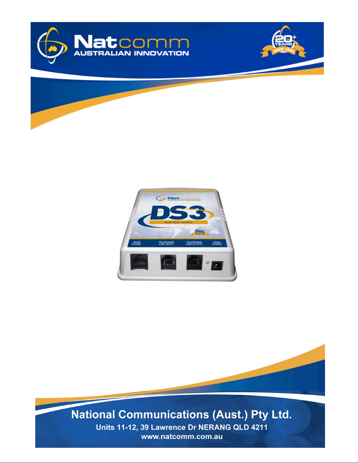
DS3
USER GUIDE
For Technical Assistance
Please Ph: 07 5596 5128
or Email : [email protected]
Natcomm Page 1
Page 2

DESCRIPTION
This Product Guide describes the installation and operating instructions of our DS3
model DOOR STATION Controller, which is designed to connect to a Specially
designed Door Phone (see page 4), when used on an ordinary PSTN residential
telephone line.
Your DS3 Controller is completely TRANSPARENT in operation, so it will not affect the
normal operation of your telephone line in any way. It is Designed to RING all of your
Normal Telephones when a Visitor presses the Call Button of the attached Door Phone.
You need only Answer ANY Ringing Telephone to converse with your visitor.
Model DS3 has the additional capability where it cans DIAL OUT to your Cell Phone
(or any other user programmed number) so that you can still Answer your Door
Phone when you are away from home. DS3 can either DIAL OUT immediately, or
after a User Programmed Number of Unanswered Rings.
ONE or TWO Door Phones can be connected to the DS3 unit. They must be
connected in parallel with each other. Either Door Phone can trigger a Door Phone
call. If you use TWO Door Phones connected in parallel, then Audio will be present
at both Door Phones at the same time.
If you wish to operate 2 completely separate Door Phone zones, when using 2 Door
Phones, you can do so by fitting an additional Model DS1 Controller (our less
expensive model without Lock Control and Dial Out) on the same telephone line. In
this situation, each Door Phone will then have separate audio communication and
you will be able to use the Dual Lock Control of DS3 to control up to 2 separate lock
zones.
If you need the additional features of DS3 at Both Door Phone Zones, you should
use another Model DS3 Controller with Dial Out and Call Advice Tones.
Once correctly installed, DS3 will RING your all of telephones that are connected to
it as soon as it is activated by a visitor pressing the Call Button of the attached Door
Phone. Unlike the more basic Model DS3 and DS2 Controllers, DS3 also has the
ability to select from 4 different ring outputs.
DS3 will work with both Corded and Cordless Phones. A small number of Older
Cordless Telephones may not ring differently as they are designed to ignore the
incoming ring pattern and output their own ring. For this reason, your unit can be
set to output FIVE quick ‘beep’ tones (advice tones) immediately after answer, to
advise you that the incoming call is from your Door Phone.
Page 2 Natcomm
Page 3
OPERATION WITHOUT A TELEPHONE LINE
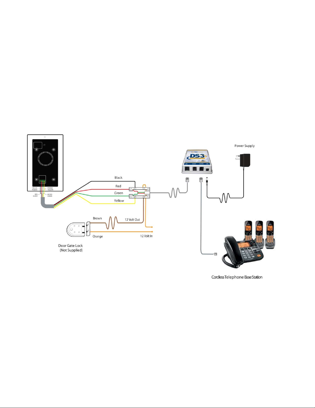
DS3 will also work WITHOUT connection of a Telephone Line. In this situation, leave
the Line Input port of DS3 vacant (see the diagram below).
DS3 will ring all attached telephones as normal. This will suit the many users that no
longer use a fixed telephone line. The diagram below shows a wiring diagram used
when a Single Lock Control relay is being used.
Natcomm Page 3
Page 4
DOOR PHONE RANGE
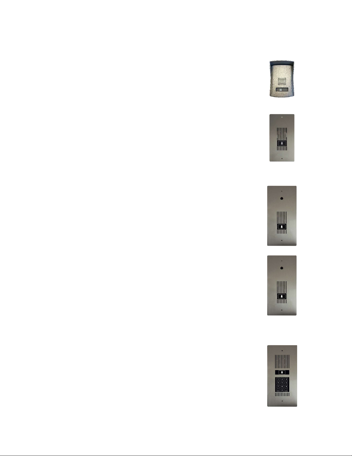
A choice of Five Door Phones is provided for use with our range of Door Station Controller units:
Model DP1 - SURFACE MOUNT
Molded plastic unit, designed for easy surface mounting
direct onto your wall surface.
Blue LED Night illumination.
(100mm Wide, 133mm High, 32mm Depth).
Model DP2 - FLUSH MOUNT Compact Size
Marine Grade Stainless Steel face plate.
Touch Switch operation.
Available in Vertical (Displayed) or Horizontal orientation.
Blue LED Night illumination.
Optional Surface Mounting Kit is available.
(107mm Wide, 204mm High, 30mm (D).
Model DP3 - FLUSH MOUNT Standard Size
Marine Grade Stainless Steel face plate.
Fitted with a Sealed Perspex Camera Hole and rear Mounting Studs to
allow you to fit your own Camera. Vertical or Horizontal orientation.
Touch Switch operation.
Blue LED Night illumination.
Optional Surface Mounting Kit is available.
(130mm Wide, 264mm High, 37mm Depth).
Model DP4 - FLUSH MOUNT Standard Size
Fitted with a high resolution, low light Digital Colour CCD Camera.
BNC output. Available in Vertical or Horizontal orientation
Marine Grade Stainless Steel face plate
Available in Vertical (Displayed) or Horizontal orientation.
Touch Switch operation.
Blue LED Night illumination.
Supplied with Wall Mount Box to assist installation.
Optional Surface Mounting Kit is available.
(130mm Wide, 264mm High, 37mm Depth).
Model DP5 - FLUSH MOUNT Standard Size
Fitted with intelligent Pedestrian Access Keypad.
Touch Switch operation with 99 User Codes.
Available in Vertical (Displayed) or Horizontal orientation
Marine Grade Stainless Steel Face plate.
Blue and White LED Night illumination.
Supplied with Wall Mount Box to assist installation.
Optional Surface Mounting Kit is available.
(130mm Wide, 264mm High, 30mm Depth).
Page 4 Natcomm
Page 5
DOOR PHONE COVERS
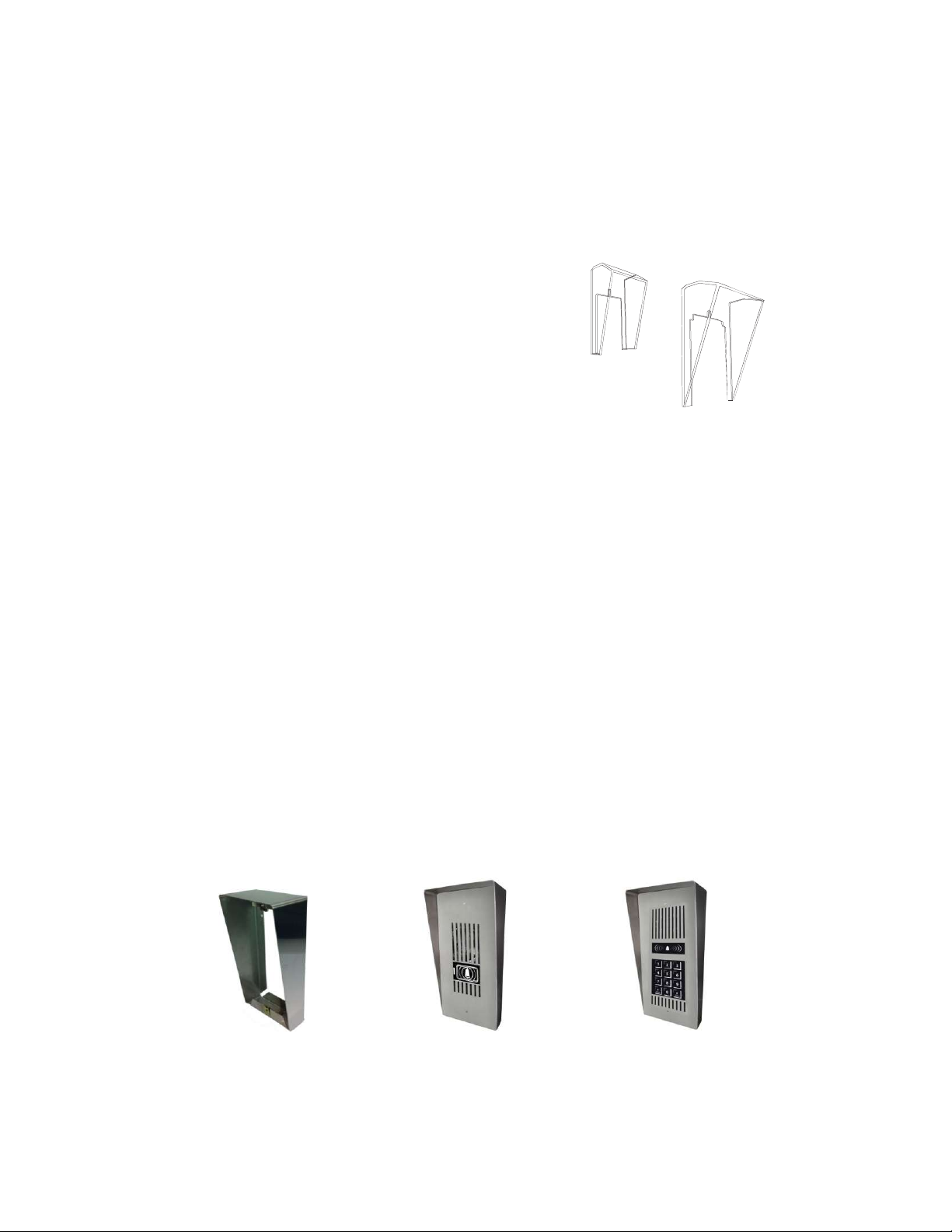
If your Door Phone is not under cover, a Strong Transparent DOOR PHONE COVER
is highly recommended to prevent water from gradually permeating through to the
electronics of the Door Phone. RRP is just $A 39.00.
Model DPC1 for DP1 Door Phone
Model DPC2 for DP2 Door Phones
Model DPC3 for DP3, DP4, DP5 Door Phones
You can alternatively use one of our Surface Mounting Kits which provides a Rain
deflector. See below.
SURFACE MOUNTING KITS
Stainless Steel (304) Surface Mounting Kits are available for all Model DP2 to DP5
Door Phones, so that your Door Phone can be mounted ONTO a wall surface, rather
than into it.
Two separate surface mounting kits are available, to cater for the different sized DP2DP5 Door Phones:
Model SMK2 for DP2 Door Phones
Model SMK3 for DP3, DP4, DP5 Door Phones
Natcomm Page 5
Page 6

OPERATION
When a visitor at your door or gate presses the call button on your NATCOMM
Door Phone, DS3 will ring all of the telephones connected to your line up to 10
times (the number of rings can be changed).
By simply answering any ringing telephone on your line, you will be immediately
connected direct to your visitor, so that you can converse with them.
If you are already on a telephone call, the DS3 Controller will instead inject a faint
'Beeping Tone' into the background of your call to alert you. You will then be able
to place your existing call 'ON HOLD' and switch to the door or gate by simply
pressing the ## key (twice) on your telephone. To resume your original call, all
you need do is to press ## again. This can be done as many times as required.
If you have a LOCK MECHANISM fitted, you can open a gate or door lock during
this call and allow your visitor to enter, by simply pressing the * * key on your
telephone.
If you have the SECOND LOCK CONTROL FACILITY fitted, you can also open
an ALTERNATIVE gate or door lock during this call, by simply pressing * 2 on
your telephone. This command will release Gate Lock 2 until you Hang Up the
telephone.
Note:
Pressing *3 can also close the second internal relay and leave it closed.
Pressing *4 can also open the second internal relay and leave it open.
Alternatively, the SECOND LOCK RELAY option can be used to START and
STOP another Device such as a VIDEO CAMERA, DISPLAY MONITOR,
RECORDER or to TURN ON and then TURN OFF a 12V LIGHT (or a 240V Light
with the Power Control Unit Accessory).
The Other Device will be SWITCHED ON as soon as the Call Button is pressed
on the supplied Door Phone and will SWITCH OFF, 01-99 seconds after the Door
Phone call has terminated, as programmed on page 27.
The Second Relay can also be used to signal to a Home Automation system that a
Door Phone call has been initiated.
Page 6 Natcomm
Page 7

DIAL OUT OPERATION
If your site is unattended, DS3 can DIAL OUT and CONNECT THE DOOR PHONE
CALL to a Pre-Programmed Telephone Number or a Mobile Telephone number (See
Pages 25-26 for Programming Details).
It can do so Immediately, or only if the Door Phone call has not been answered internally
by a preset number of rings.
Dial Out Immediately (Press #1), Dial Out after Ring Count (Press #2) and Disable
Dial Out (Press #3) are all set via Touch Tone commands from ANY Telephone on your
line, at any time (except in Programming Mode).
To set ‘Unattended Mode’
(Dials out immediately)
Pick up any telephone, press #1 and then hang up.
(you will hear 1 ‘beep’ to confirm setting)
In this mode DS3 will DIAL OUT to the Programmed Number as soon as the Door
Phone is triggered by your visitor call.
To set ‘Attended Mode’
(Only Dials out after ring count)
Pick up any telephone, press #2 and then hang up.
(you will hear 2 ‘beeps’ to confirm setting)
In this mode DS3 will only DIAL OUT to the Programmed Number if the Door Phone
call is not answered before the preprogrammed ring count.
To set ‘Disable Dial Out’
(will not Dial Out)
Pick up any telephone, press #3 and then hang up.
(you will hear 3 ‘beeps’ to confirm setting)
This Mode will totally DISABLE the DIAL OUT facility:
Note - Your DS3 is set by DEFAULT to ‘Disable Dial Out’, to ENABLE DIAL OUT,
you MUST press #1 or #2 as appropriate.
Natcomm Page 7
Page 8

OPERATION SUMMARY
Your telephones will ring whenever a visitor at your door or gate presses the call
button on your Door Phone(s).
You can answer the Door Phone call by simply picking up any telephone
connected to your line. You will then be able to converse with your visitor.
If you have an ELECTRIC LOCK fitted, you can release it (open it) by pressing **
on your telephone.
If you are already on a telephone call and the Door Phone is activated by a visitor,
you will be alerted with a tone.
You can place your existing call 'ON HOLD' and switch to the DOOR PHONE at
your door or gate by pressing ## on your telephone.
You can return to the telephone call by pressing ## on your telephone.
If there is an incoming telephone call while you are on a DOOR PHONE call, you
will be alerted with a tone.
You can place your existing call 'ON HOLD' and switch to the telephone call by
pressing ## on your telephone.
To resume your original call, all you need do is press ## on your telephone again.
** opens LOCK 1
*2 opens LOCK 2
*3 activate LOCK RELAY 2 (leave it ON)
*4 de-activate LOCK RELAY 2 (leave it OFF)
## switch between lines
Page 8 Natcomm
DS3 COMMANDS
Page 9
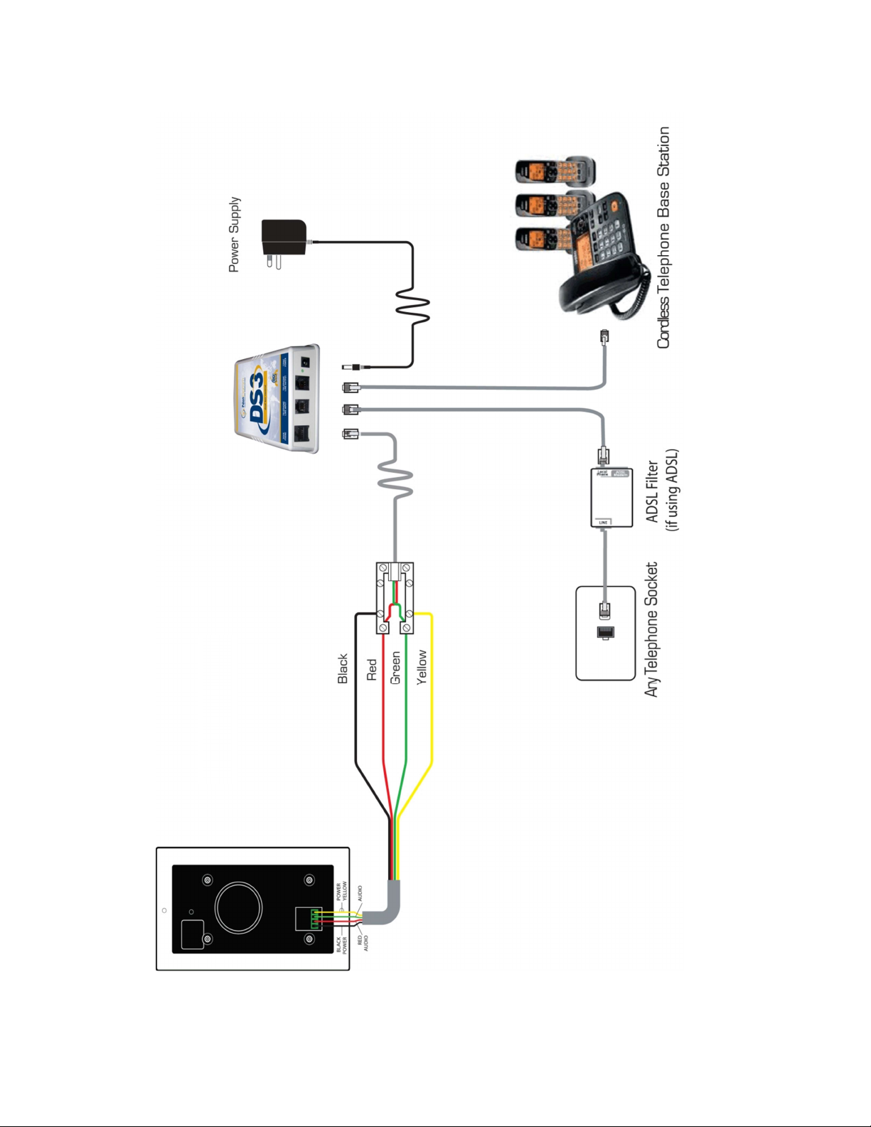
SINGLE CORDLESS BASE STATION
Note:
DP1 Door Phone
Without Lock Operation
only requires 2 wires
Natcomm Page 9
Page 10
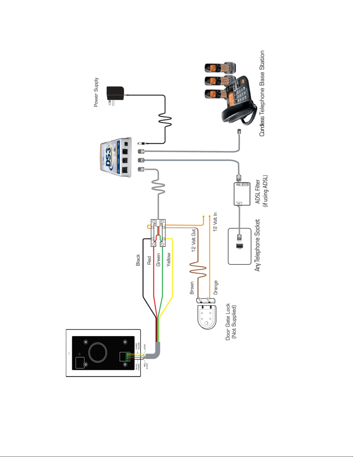
WITH SINGLE LOCK CONTROL
Note: DP1 Door Phone
only requires 2 wires
Page 10 Natcomm
Page 11
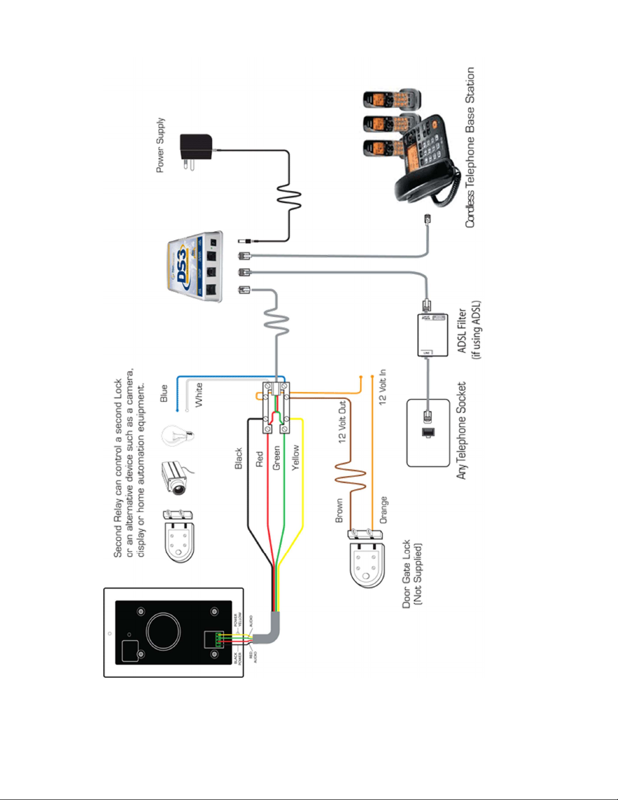
11
WITH DUAL LOCK CONTROL
Natcomm Page
Page 12
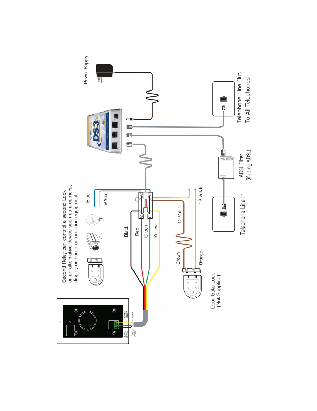
INSTALLATION WHEN USED WITH
MULTIPLE TELEPHONE SOCKETS
Page 12 Natcomm
Page 13

13
INSTALLATION FOR CORDLESS PHONE USERS
If you operate a Single Cordless Phone Base Station only, with 1 or more handsets,
then installation is very easy. See the Diagrams on pages 9-11.
1. Unplug the Base Station Telephone Cable from the Telephone Socket.
2. Connect this cable to the LINE OUT Port of DS3.
3. Connecting the LINE IN port of DS3 to the telephone using a supplied cable.
Installation by a technician is not required.
4. Arrange for a Suitable Qualified Technician to install your Door Phone in the
required location, following the Instructions supplied with the Door Phone.
MULTI SOCKET USE INSTALLATION
Installation is required by a Suitably Qualified Technician
Where you will operate cordless or corded telephones connected to more than 1
telephone socket, an approved installation technician will need to fit your DS3 direct
onto your incoming telephone line, immediately ahead of your first telephone
socket, so that your telephone line connects to all of your telephone sockets through
it.
DS3 has been designed so that it will not interfere with the normal use of your
telephone line in any way. In the event of a malfunction or power cut, your telephone
line will continue to operate.
Your DS3 unit should be fitted inside the home or office. If it is fitted outside next to
the Door Phone, then it MUST be fitted within a Water Proof enclosure.
These instructions are for suitably qualified Installation Technicians.
1)
Locate the FIRST telephone socket on the line. Fit a New Telephone socket
next to it, or alternatively replace the Existing Telephone socket with a Double
Outlet RJ type telephone socket.
Label the Original Telephone Socket - LINE IN
Label this New Telephone Socket - LINE OUT
Natcomm Page
Page 14

Transfer all of the Remote Extension wires from the Original Telephone
2)
socket (now labelled Line In) to the corresponding positions on the New
Telephone Socket (labelled Line Out).
--------------------------------------------------------------------------------------------
A) Leave the original incoming Telephone Line wires connected to the
ORIGINAL Telephone Socket.
B) These Telephone Wires connected to the NEW Telephone socket (labelled
Line Out) are the connections to all of your EXTENSION telephones.
C) If a telephone is to be used at this same socket location, it should be
connected to the LINE OUT port of DS3, using a standard RJ style Modular
Double Telephone adaptor.
VERY IMPORTANT NOTE - LOSS OF TELEPHONE SERVICE
D) Should the DS3 device ever need to be removed, or if it becomes faulty,
you will lose your telephone service.
To overcome this, you should remove the cable from the LINE IN port of
DS3 and connect this cable direct to the new LINE OUT socket (you
will need to remove the existing cable connected to the LINE OUT
socket first). This will re-connect your telephone service.
--------------------------------------------------------------------------------------------
3)
Now connect the LINE INPUT port of DS3 to the LINE IN socket, using the
supplied RJ to RJ telephone cable.
4)
Connect the LINE OUTPUT port of DS3 to the LINE OUT telephone socket,
using the other supplied RJ to RJ telephone cable.
Connect the supplied 12VAC (or 12VDC) power adaptor to DS3, and switch
5)
the POWER ON.
6)
Connect the SUPPLIED DOOR PHONE to the DOOR PHONE PORT of DS3.
See page 14 for important details.
For convenience, an interface unit with screw terminals is supplied and should
be connected to the DOOR PHONE PORT using the supplied RJ to RJ cable.
Run a solid core telephone cable (preferably CAT5) between the interface unit
and the Door Phone. Now refer to your Door Phone User Guide.
Page 14 Natcomm
Page 15

15
CONNECTING THE DOOR PHONE
Our Door Phones all use a 4 Pin Phoenix Socket on the rear of the Door Phone for
Connection to ANY Natcomm Controller. A 4 Pin Phoenix Plug is supplied with all
Door Phones which allows 4 wires from the Door Phone to connect to the DS3
Controller. A solid core cable should be used to interconnect the devices. Cat5 cable
is ideal and will allow the units to be up to 300m apart without any loss of performance.
Model DP1 DOOR PHONE
DP1 is designed to be mounted onto your wall surface. With DP1 this is done by
separating the Door Phone unit from the integral backing plate, secured by a
screw underneath the unit. The backing plate should then be screwed to the wall
surface, before re-attaching the Door Phone with the securing screw.
With DP1 this is done by separating the Door Phone unit from the integral
backing plate, secured by a screw underneath the unit. The backing plate should
then be screwed to the wall surface, before re-attaching the Door Phone with the
securing screw.
Model DP2-5 DOOR PHONES
Our DP2-DP5 are by default designed for Flush Mounting, or they can all be
Surface Mounted onto your wall surface using the appropriate Surface Mount
Kit (SMK). Wall Mount Screws are supplied with all units.
AUDIO & POWER CONNECTION
Audio Connection – The Centre 2 Pins of the Door Phone Socket are the Audio
Pair. They should connect to the 2 Pins either side of the Centre 2 pins of the 8 pin
RJ45 socket of DS3 (Pins 4 & 5). Polarity is not important.
If you plan to use the interface unit, then the terminals for the GREEN and RED wires
should be connected to the center 2 positions of the 4 position Phoenix Plug.
Power Connection – The Outer 2 Pins of the Door Phone Socket are the Power
Pair. They should connect to the 2 Pins either side of the Centre 2 pins of the 8 pin
RJ45 socket of DS3 (Pins 3 & 6). Polarity is not important.
If you plan to use the interface unit, then the terminals for the YELLOW and BLACK
wires should be connected to the outside positions of the 4 position Phoenix Plug.
The LED on the DOOR PHONE should turn ON (DS3 must be ON).
Natcomm Page
Page 16

LOCK CONTROL
Your DS3 is provided with TWO internally fitted relays which can be used to control
TWO LOCKS or ONE LOCK and ONE OTHER DEVICE such as a Video Camera,
Recorder or Light.
Relay Specification - Dry Relay Contacts rated at 12V/1Amp.
Do not use the supplied DS3 Controller 12V plug pack to also provide 12V power
for the lock, as this may cause damage to DS3. You must use a separate 12V
source, with a maximum rating of 12V/1A.
LOCK 1 FACILITY
To OPEN the Door/Gate Lock after answering a call from your DOOR PHONE you
need to press ** on your telephone. The lock will remain open for 10 seconds (Default
setting). It can be set from 01-99 secs.
Your Door/Gate Lock can also be OPENED at any time by picking up any telephone
and dialling** . The Door/Gate Lock will remain UNLOCKED for 10 seconds (can be
01-99 secs).
You do not need to receive a call from the Door Phone first.
LOCK 2 FACILITY
To OPEN the ALTERNATIVE Door/Gate Lock after answering a call from your DOOR
PHONE you need to press *2 on your telephone. The lock will remain open until you
HANG UP your telephone.
Your ALTERNATIVE Door/Gate Lock can also be OPENED at any time by picking up
any telephone and dialling *2. The Door/Gate Lock will be LOCKED as soon as you
hang up. You do not need to receive a call from the Door Phone first.
With the LOCK 2 facility, you can also press *3 and then HANG UP at any time, which
will CLOSE the Internal Relay and leave it closed.
You can then press *4 and then HANG UP at any time, which will OPEN the Internal
Relay and leave it open.
Page 16 Natcomm
Page 17
17
LOCK INSTALLATION
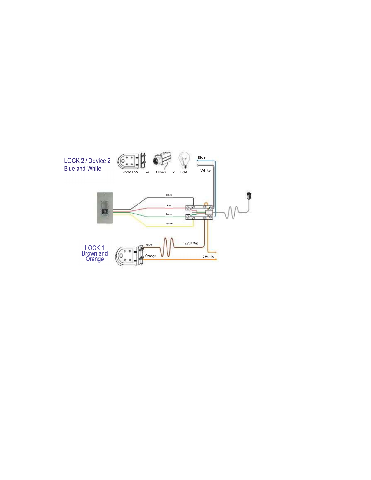
The contacts of each Internal relay of DS3 are accessed by the supplied
connection adaptor. Both DS3 Relays are Dry Contact Relays rated at 12V/1A.
The polarity of the Relay connection wires is not important.
Lock 1 should connect to Brown and Orange terminals.
Lock 2 or Device 2 should connect to Blue and White terminals.
NOTE- Do not use the supplied DS3 Controller 12V plug pack to also
provide 12V power for the lock, as this may cause damage to DS3. You
must use a separate 12V source, with a maximum rating of 12V/1A.
If problems are experienced, please refer to page 29 for troubleshooting
tips.
Natcomm Page
Page 18

USERS WITH ADSL
DS3 can be used with ADSL on the same telephone line.
However it is ESSENTIAL to fit a SINGLE High Quality ADSL filter immediately ahead
of the DS3 Controller. Failure to do so, or use of additional ADSL filters connected
direct to your telephones, WILL cause problems in the operation of your DS3 Controller
and ADSL service.
Please Note - Basic ADSL FILTERS, designed for separate connection to each
telephone on your line (as usually supplied with ADSL modems) are not suitable.
If you use NBN FIBRE, SATELLITE or CABLE for your Internet, you will NOT need an ADSL filter.
USERS WITH DIAL OUT ALARMS
DS3 can be used with a DIAL OUT SECURITY ALARM on the same telephone line.
However, to avoid conflict, it is ESSENTIAL to fit the DIAL OUT SECURITY ALARM
on the telephone line AHEAD of the DS3 unit.
If ADSL is also to be used on this same line, then it is ESSENTIAL to fit a single High
Quality ADSL filter immediately ahead of the DS3 Switch, being the first point on the
telephone line.
This means that the Security Alarm, DS3 Line Sharer and all telephones connected
on the telephone line have adequate filtering from the high frequency ADSL
communication.
Page 18 Natcomm
Page 19

19
HANG UP AFTER DIAL OUT
DS3 incorporates a HANG UP TONE DETECTOR which is designed to detect
the US specification hang up tones that will be present when DS3 has made an
outgoing call to a programmed Cell Phone or External Number after the
completion of the call. This process is fully automatic.
When installed on PBX systems, the Hang Up tone generated may be outside
of the cadence and frequency normally used in the USA for Hang Up tones. In
this situation, DS3 may not hang up until the Maximum Door Phone Call Time
has elapsed. The Hang Up detector, looks for:
1. A Tone Frequency between 200Hz and 600Hz.
2. A Tone Duration between 300mS and 600mS.
3. A 50% Duty Cycle +/- 20%
(Ie ON and OFF periods should be the same +/- 20%)
You can adjust your PBX system to generate Hang Up tones as per the above
specification, or to output normal USA Hang Up tones.
OR
You can PRESS ANY TOUCH TONE NUMBER from (0 to 9) on your telephone
to cause an immediate disconnection of the call. Note: # and * cannot be used,
as they are used for other functions.
AND/OR
You can set the Maximum Door Phone Call Time to a time less than 99 seconds
but which is still long enough to communicate with your visitors. DS3 will
terminate all Door Phone calls at this time setting.
ELECTRO MAGNETIC INTERFERENCE
At some sites, Electro Magnetic Interference (often caused by older poor quality
‘switch mode’ power supplies) can interfere with DS3’s ability to reliably detect
these tones. As a result, DS3 may not hang up until the Maximum Door Phone
Call Time has elapsed.
Should this occur, you can overcome the problem by moving the offending ‘switch
mode’ power supply away from the DS3 and its approved power supply. The
distance to be moved, will depend on the level of noise generated and will need to
be determined by trial and error.
Natcomm Page
Page 20

PROGRAMMING OPTIONS
DS3 is pre-programmed with the most commonly used settings. In most cases,
you will not need to change any settings, with the exception of Entering the Dial
Out Number. However, a number of settings can be changed to allow you to
customize DS3 to meet individual requirements. DS3 will retain your settings
even if power is disconnected.
DOOR PHONE CALL ADVICE TONES
5 shorts ‘beeps’ can be injected into the Door Phone call, immediately after
answer, to advise you that the incoming call has originated from your Door
Phone. This facility is very useful for those users who may use cordless phones
that do not ring differently when there is a Door Phone call.
Allowable Range : ON or OFF
Default Setting is : OFF
MAXIMUM DOOR PHONE CALL TIME
DS3 unit has been pre-programmed to detect Australian ‘Hang Up’ tones when
a ‘Dial Out’ call is complete and then terminate the ‘Dial Out’ call connection.
Due to the possibility that your equipment may not generate Australian ‘Hang
Up’ tone, a maximum allowable time ‘Dial Out’ call limit can be set.
Allowable Range : 15 to 99 seconds
Default Setting is : 99 seconds
NUMBER OF RINGS before stopping or initiating Dial Out
DS3 will ring your telephones 10 times when it is triggered by a Door Phone call.
This can be changed from 1-99 rings. DS3 has the ability to DIAL OUT to an
external telephone number or mobile number, if the call is unanswered after the
programmed NUMBER OF RINGS.
Allowable Range : 1 to 99 rings
Default Setting is : 10 rings
RING OUTPUT PATTERN
DS3 unit outputs a Single 1 second repeating ring pattern when activated by the
attached Door Phone. You can program DS3 to output Two, Three or Four 1
second rings.This feature is useful when you plan to use more than ONE DS
unit on your line, as this will allow each unit to generate a different ring pattern.
Allowable Range : 1 to 4 repeating rings
Default Setting is : 1 repeating ring
Page 20 Natcomm
Page 21

21
PROGRAMMING OPTIONS
LOCK 1 TIME OUT
The Lock 1 relay control facility should be used to open a gate or lock. You
can set the time which LOCK 1 will remain open after the user presses the
** command, to between 01-99 seconds. This is the time interval that the
LOCK REMAINS OPEN after pressing **
Allowable Range : 01 to 99
Default Setting is : 10
LOCK 2 TIME OUT
The Lock 2 relay control facility can be used for either:
A Second Gate or Door LOCK
To SWITCH ON and OFF a VIDEO DEVICE or a 12V LIGHT
Or to alert a HOME AUTOMATION SYSTEM of a visitor
1) If a separate Lock is to be used, set this command to: 00.
Then to Open Lock 2 you can press *2
Lock 2 will remain OPEN until you hang up the Phone.
2) If a Video Device, Light or Home Automation System is fitted at the Door
or Gate), set this command to: 01 to 99.
01 to 99 is the time interval in seconds that the DEVICE REMAINS ON after
the Door Phone call is complete.
Allowable Range : 00 to 99
Default Setting is : 00
DIAL OUT DELAY
DS3 waits 2 seconds before dialing. When DS3 is used on some PBX
systems, this may not be long enough to obtain dial ton. The Dial Out Delay
can be increased to 6.5 seconds.
Allowable Range : 2.0 to 6.5 seconds
Default Setting is : 2.0 seconds
Natcomm Page
Page 22

RESET FACTORY DEFAULTS
DS3 can be reset back to the DEFAULT SETTINGS by entering 13579 while in the
Programming Mode.
Please Note : The Dial Out Number and Dial Out Mode if programmed (#1, #2 or #3)
will NOT be Reset as part of the Factory Default reset procedure.
PROGRAMMING NOTES
The following notes provide important information about the programming
procedure:
1) To enter PROGRAMMING MODE you must turn OFF POWER to your unit and
then switch POWER ON AGAIN.
2) Using ANY TELEPHONE connected to DS3, PRESS # within 30 seconds.
3) DS3 must be not connected to a telephone line in order for your Telephone to
generate the DTMF Touch Tones that it uses for programming its functions.
4) You will hear 3 short ‘beeps’ to confirm you are in programming mode.
5) Individual Parameter Programming Entries are also carried out by pressing
further keys on the attached telephone.
6) Your unit will generate 1 short ‘beep’ to confirm acceptance of command.
7) Your unit will generate 1 long ‘beep’ to advice of an entry error.
IMPORTANT NOTE
Note - After each power up DS3 will prepare to enter programming mode for 30
seconds. During this time, dial tone is not immediately available.
You can cancel out of this mode (before the 30 second limit) and achieve dial
tone by Hook Flashing, Hanging Up OR pressing any DTMF Touch Tone digit
other than #.
Page 22 Natcomm
Page 23

23
PROGRAMMING PROCEDURE
1.
2.
3.
4.
A.
B.
TURN OFF POWER TO YOUR UNIT
SWITCH ON POWER AND PRESS #
(use a Telephone connected to DS3)
YOUR UNIT WILL OUTPUT 3 SHORT ‘BEEPS’ (you are in
Program Mode)
If you do not hear 3 beeps, return to the start (1).
ENTER ANY PROGRAMMING COMMANDS AS FOLLOWS:
(Note - You can change one or more parameters in any order)
NUMBER OF RINGS
To enter the NUMBER OF RINGS press #1xx where xx = number
of rings and can be 01-99 (for example, press #115 for 15 rings)
DOOR PHONE CALL ADVICE TONES
To disable TONES press #40
To enable TONES press #41
C.
MAXIMUM DOOR PHONE CALL TIME
To enter the MAX CALL TIME press #3xx
xx = time limit in seconds and can be 15-99
(for example, press #360 for 60 seconds)
Note : If you enter * before the 15-99, it will increase the maximum Dial Out call time by 10.
Ie; entering #3*50 will set a maximum dial out time of 500 seconds, instead of 50 seconds.
D.
DIAL OUT FACILITY
To enter the DIAL OUT TELEPHONE NUMBER
press **x**
where x = the complete phone number.
ie : if the Dial Out Telephone Number is 0401234567 you should
press
**0401234567**
Note - You then need to ENABLE the Dial Out facility to dial out
after the ring count or immediate. See page 7.
Natcomm Page
Page 24

E.
F.
G.
H.
RING OUTPUT PATTERN
To select a different Repeating Ring Output: press #8x
x = number of repeat rings before pausing
It can be set from 1-4 (repeating rings)
(for example, press #83 for 3 repeating rings)
LOCK 1 SET UP
To enter the LOCK 1 OPEN TIME press #6xx
xx = time limit in seconds that LOCK 1 will remain open after pressing **.
It can be set from 01-99 (seconds)
(for example, press #630 for 30 seconds)
LOCK 2 SET UP
To set LOCK 2 to control a SECOND LOCK press #200
To set LOCK 2 to SWITCH ON/OFF a device press #2xx
xx = time limit in seconds that attached device remains ON after hang up.
xx = can be set from 01-99 (seconds)
(for example, press #230 for 30 seconds)
DIAL OUT DELAY
To increase the DIAL OUT DELAY press #5x
x = Dial Out Delay in seconds
If x = 0 - delay is 2.0 seconds If x = 5 - delay is 4.5 seconds
If x = 1 - delay is 2.5 seconds If x = 6 - delay is 5.0 seconds
If x = 2 - delay is 3.0 seconds If x = 7 - delay is 5.5 seconds
If x = 3 - delay is 3.5 seconds If x = 8 - delay is 6.0 seconds
If x = 4 - delay is 4.0 seconds If x = 9 - delay is 6.5 seconds
I.
RESET TO FACTORY DEFAULT SETTINGS
To RESET to Factory Defaults, press 13579
TO EXIT PROGRAMMING MODE - HANG UP.
ALL ENTRIES ARE SAVED IN PERMANENT MEMORY.
Page 24 Natcomm
Page 25

atcomm
TROUBLESHOOTING LOCK CONTROL
Both DS3 Relays are Dry Contact Relays rated at 12V/1A.
If you are having trouble controlling the LOCK or GATE STRIKE, please
trouble shoot by using the following procedure:
Test that you receive the correct voltage across the terminals of the supplied
connection adaptor, when ** or *2 is pressed on the attached telephone.
Lock 1 should connect to Brown and Orange terminals.
Lock 2 device should connect to Blue and White terminals.
If the correct voltages are not present investigate all wiring to and from your lock
and power source.
If the correct voltage is present, short across the two terminals and your electric
lock should operate.
If your lock still does not operate, there will be a problem with wiring between your
power supply, electric lock and connection box.
If your lock operates, then the problem is located in the wires of the connection
box, the RJ to RJ lead connecting to the DS3 unit or the relay within the DS3 unit
itself. If possible, please bypass the connection box and the RJ to RJ lead
connecting to the DS3 unit by feeding the two power supply wires of the electric
lock into an RJ45 plug in positions 2 & 7 (Lock 1) and 1 & 8 (Lock 2).
If the lock then works with ** or *2, then the problem is in the connection box or the
RJ to RJ lead connecting to the DS3 unit.
If the lock still does not work with **, then the problem may be within the DS3 unit,
or interference is preventing DS3 from detecting the ** command.
ADSL Interference or Electromagnetic Interference (EMI) caused by Switch
Mode Power Supplies or Uninterruptable Power Supplies can prevent the **
touch tones from being detected by DS3. Follow the instructions on page 20.
If your problem is still unresolved, please Email Natcomm at [email protected]
to report the above results and arrange for further advise or repair.
IMPORTANT NOTE - You must not use the Power Adaptor supplied with DS3
to power either Door Lock or Strike.
Page 25 N
Page 26

TROUBLESHOOTING AUDIO
If you are having trouble with AUDIO COMMUNICATION between the DOOR
PHONE and ANY TELEPHONES on your line, please follow the procedure
below.
Most problems are caused by site specific conditions. Through a process of
elimination, the source of problems can be determined and then rectified.
If you use ADSL on your telephone line, ensure that you have a High Quality
ADSL2+ filter fitted to your telephone line ahead of the DS3 Controller.
If you have recently updated your ADSL service, your old filter is unlikely to be
compatible with your new service, as ADSL2+ requires different filtering to the
ADSL2 service or the original ADSL1 service. If you are using FIBRE, SATELLITE
or CABLE for your Internet, you will NOT need an ADSL filter.
Your BALANCE POT, located on the back of the Door Phone may need adjusting
as described on page 16.
If you are still having audio quality problems, they can be caused by EMI (Electro
Magnetic Interference) from some Switch Mode Power Supplies and some low
end UPS units (Uninterruptable Power Supplies).
Switch Mode Power Supplies can be easily identified because they are very light,
due to the fact that they do not use a transformer. Many brands of these power
supplies are well known to generate high levels of EMI.
Please TURN OFF any SWITCH MODE POWER SUPPLIES located near the
DS3 controller (and its power supply) and test if the problem is resolved.
If the DS3 Power Supply is connected to an Uninterruptable Power Supply,
remove it and test if the problem is resolved.
If you are still having audio quality problems, then you may be picking up
interference (60 Hz power or other interference) from the telephone line input, or
the cable leading to your Door Phone.
To test for this, you need to temporarily isolate our equipment from the existing
devices/cable, using the following procedure:
Disconnect the telephone cable from the LINE OUT port of your unit and connect
a single corded telephone into this port. Now test communication with this single
phone.
Page 26 Natcomm
Page 27

atcomm
TROUBLESHOOTING AUDIO
If satisfactory operation can not be achieved, you should fault find your
problem with the wiring or telephones downstream of our unit by connecting
them to our unit 1 device at a time.
If satisfactory operation cannot be achieved, you should disconnect the
telephone cable from the DOOR PHONE port of your DS3 unit and
temporarily run NEW CAT5 cable from the DS3 to your DOOR PHONE.
Alternatively, you can remove the Door Phone from its normal position and
move it closer to the DS3 unit so that you can connect it using a temporary
new CAT5 cable. Please ensure this temporary test cable is no less than 20
feet away from your DS3 unit in order to prevent Audio Feedback.
If satisfactory operation can be achieved, you should fault find your problem
in the wiring leading to the DOOR PHONE unit.
If satisfactory operation cannot be achieved, you should disconnect the
telephone line input to the LINE IN port of your DS3 unit. (Note: with the
telephone line disconnected, audio communication can be achieved, but
DTMF operation will not work).
If satisfactory operation can be achieved, you should fault find your problem
caused by the incoming telephone line. If you are using ADSL, ensure that
you are using a single high quality ADSL filter. These devices are available
from your Dealer.
If your problem is still unresolved, please call (07) 5596 5128 to report the
above results and arrange for further advise or repair.
Page 27 N
Page 28

SPECIFICATIONS
Dimensions (mm) : 106 (W) x 106 (D) x 43 (H)
Weight : 170g
Power Supply : 12V AC
Power Consumption : Idle - 0.5 W; Call – 0.75W
Line IN Connector : RJ 11 6 pin (2 center)
Line OUT Connector : RJ 11 6 pin (2 center)
Door Phone Connector : RJ 45 8 pin (4 center)
Relay for Lock 1 : RJ45 8 pin (pins 2 & 7)
Relay for Lock 2 : RJ45 8 pin (pins 1 & 8)
Power Connector : 2.5mm barrel connector
ACMA COMPLIANT : Supplier Number N782
Ringer Equivalence Number : 0.1 REN
WARRANTY
This device is guaranteed against defects from workmanship for a
period of two years (24 months) from the date of purchase.
In the event of a problem, please call ph 07 5596 5128 for assistance
and if necessary, a Return Authorization. You should then return your
unit, along with the proof of purchase date, and a written statement
about the nature of the problem.
The Manufacturers obligation is solely to repair or the product. The
product may be replaced at the discretion of the Manufacturer. The
warrantor is not liable for any incidental or consequential damages due
to such defects.
This Warranty shall not apply to any unit which has been subject to
alteration, modification, abuse, negligence, accident, external
voltage/ lightning surge or used in any manner contrary to these
instructions.
The user is responsible for freight costs to the repair point. The
warrantor will be responsible for freight costs in returning this unit back
to the user.
Damage caused to this device or attached equipment by lightning
strikes or over voltage surge is not covered under this warranty.
THE CASE IS SEALED AT THE FACTORY
OPENING THE CASE WILL VOID THE WARRANTY
Page 28 Natcomm
 Loading...