

Page 1
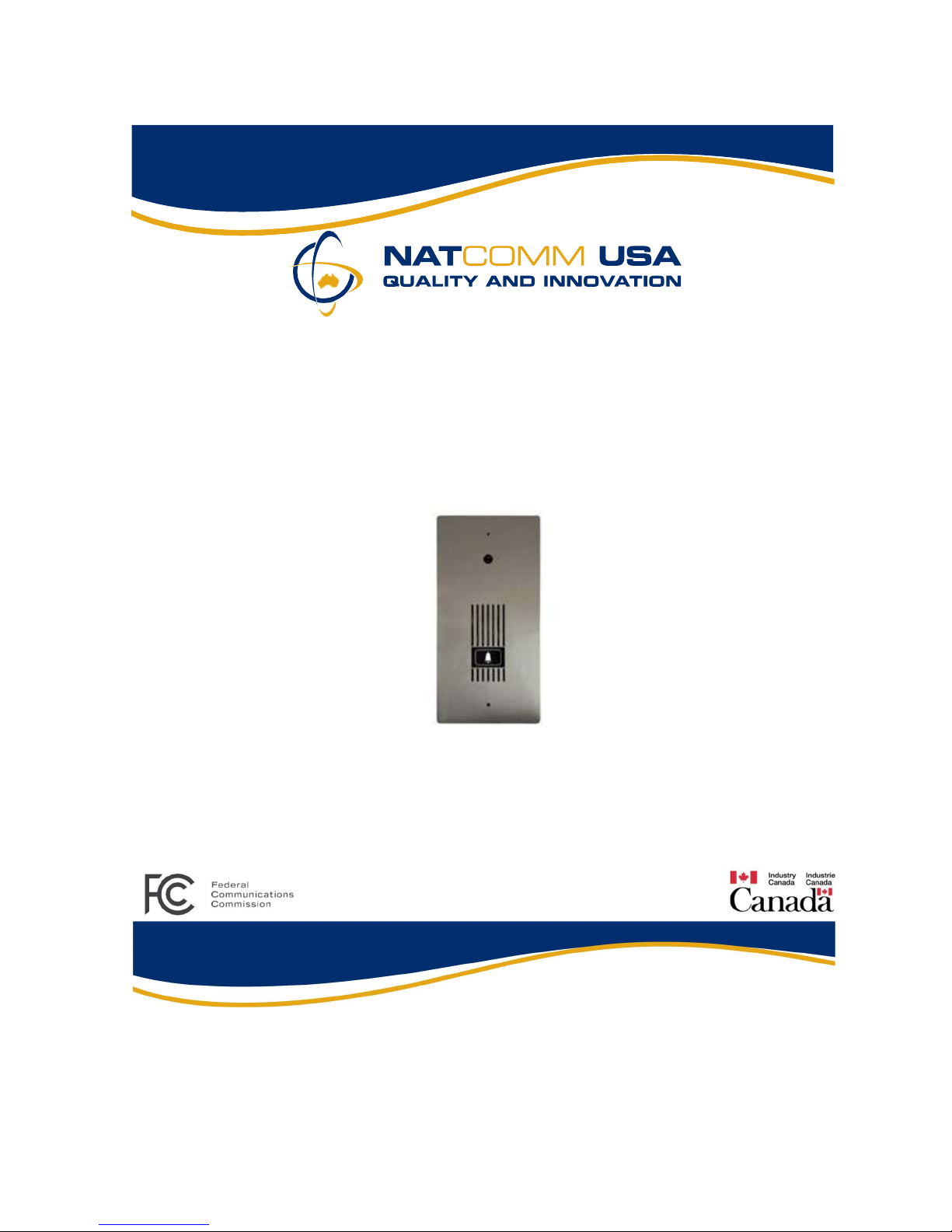
DP4
Door phone
For Technical Assistance call
the Manufacturers direct
ph 800 530 8645
8AM - 5PM
West Coast Pacific Time
NATCOMM USA LLC
Responsible Supplier Code NC
Page 2

TABLE OF CONTENTS
Description
Page
3
Door Phone Dimensions Page
Description Continued Page
Door Phone Range Page
Door Phone Performance Page
Camera Power Page
Camera Wiring Page
4
5
6
7
8
9
Mounting the Door Phone Page 10
Operation Summary Page 11
Balance Pot Adjustment Pages 12-13
Wiring Diagrams
Wiring Connection
Pages 14-15
Pages 16-17
Surface Mounting Kits Page 18
Door Phone Covers Page 19
Specifications and Warranty Information Pages 20
Page 2 Natcomm
Page 3

DESCRIPTION
Our Model DP4 Flush Mount Door Phones are specifically designed for connection
to a Natcomm Door Station Controller (Models DS1-DS6).
DP4 incorporates a Low Light, High Resolution CCD Color Camera, fitted in a
sealed plastic enclosure. The Camera Circuit uses a High Resolution SONY sensor,
which is designed to operate to at low light levels, where moon light will provide
good images.
Resolution: 380 lines
S/N Ratio: 46dB
Image Sensor: 1/4 CCD
Light Sensitivity: 2 Lux
A/V Connectors: BNC
The Camera is powered by the 4 wire connection to the Door Phone and separate
power is not required.
Important Note: Because of the additional power consumption of the Camera,
DP4 cannot be located more than 75 yards from the Door Phone controller.
DP4 has a BNC Video Output, suitable for direct connection to coaxial cable. CAT5
Video Baluns can be used, should you wish to forward the video by 2 wires of a
CAT5 cable. See pages 9-10.
The Camera Lens provides a viewing angle of 92 degrees, and is fitted behind a
sealed 0.1’ (2mm) strong transparent perspex window.
DP4 has a uses a 316 Marine Grade Stainless Steel fascia plate, with a special
polymer coating to eliminate the ‘finger print’ marks that are normally present on
Stainless Steel finishes.
Natcomm Page 3
Page 4
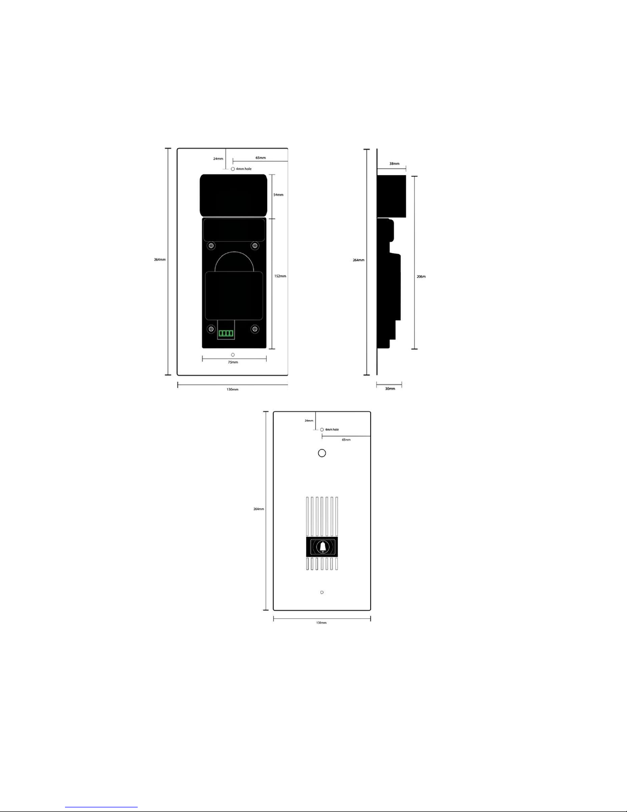
MODEL DP4 DOOR PHONE
inches
in
ches
10.4
inches
Side View
1.5
Back View
Front View
10.4
inches
5.1
Page 4 Natcomm
Page 5

DESCRIPTION
Our DP4 Door Phones can operate at distances of up to 75 yards from the Controller,
providing high quality cabling such as CAT5 is used.
Note – Our DP1, DP2 and DP5 Door Phones can operate up to 300 yards from the
Controller. The reduced distance specification of the DP4 Door Phone is due to the
increased power requirements of the Camera circuit.
All DP4 units are designed to be highly WEATHER RESISTANT and they have
proven to be reliable over long periods of time, providing they are not exposed to
direct rain. The Speaker is made of a plastic Mylar material and great effort has been
taken to maximize weather proofing all electronic components.
Note - DP4 Door Phones are not WATER PROOF.
Whenever your Door Phone is likely to be exposed to RAIN, an optional DOOR
PHONE COVER or a SURFACE MOUNTING KIT with Rain Deflector should be
used. They will ensure that rain water cannot gradually permeate through to
the electronics of the Door Phone which can cause unreliable operation and
premature failure of this device.
See Pages 18-19.
Up to two of our Door Phones can be connected to the one DOOR STATION
(CONTROLLER). This allows for a Door Phone to be located at two different
locations. In this situation, the Door Phone devices are connected in parallel and
Audio will be present on both Door Phones at the same time (see wiring connection).
An alternative is to use a 2nd Door Station Control unit on the same line (they connect
in series) and you will create Two separate Audio Zones.
Our DP4’s are designed for wall or pole mounting at a height of approximately 1.5
meters (5 feet). Visitors should stand within 0.5 meters (20 inches) of the Door
Phone for best results.
Our DP4 units incorporate a ‘touch sensitive’ switch, in order to further improve its
long term reliability and weather proofing. This switch is activated by a brief touch.
Natcomm Page 5
Page 6
DOOR PHONE RANGE
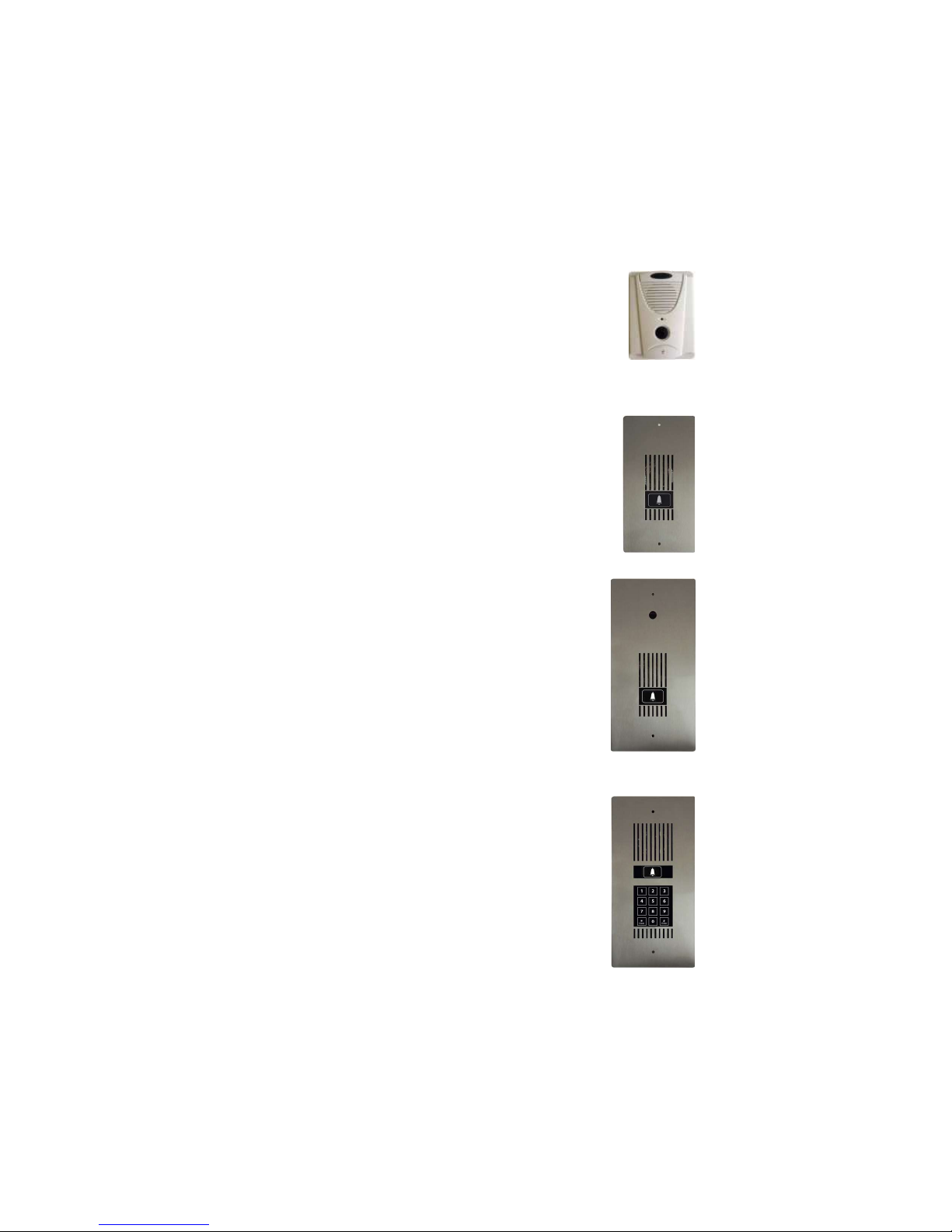
A choice of Four Door Phones are provided for use with our range of Door Station
Controller units:
Model DP1 - SURFACE MOUNT
Molded plastic unit, designed for easy mounting
direct onto your wall surface.
Red LED Night illumination.
(4 in Wide, 5.25 in High, 1.25 in Depth).
(100mm Wide, 133mm High, 32mm Depth).
Model DP2 - FLUSH MOUNT Compact Size
Marine Grade Stainless Steel face plate.
Touch Switch operation.
Blue LED Night illumination.
Optional Surface Mounting Kit is available.
(4.2 in Wide, 8 in High, 1.2 Depth).
(107mm Wide, 204mm High, 30mm (D).
Model DP4 - FLUSH MOUNT Standard Size
Fitted with a high resolution, low light Digital Color CCD
Camera. BNC output.
Marine Grade Stainless Steel face plate
Touch Switch operation.
Blue LED Night illumination.
Supplied with Wall Mount Box to assist installation
Optional Surface Mounting Kit is available.
(5.1 in Wide, 10.4 in High, 1.45 in Depth).
(130mm Wide, 264mm High, 37mm Depth).
Model DP5 - FLUSH MOUNT Standard Size
Fitted with intelligent Pedestrian Access Keypad.
Touch Switch operation with 99 User Codes.
Marine Grade Stainless Steel Face plate.
Blue and White LED Night illumination.
Supplied with Wall Mount Box to assist installation
Optional Surface Mounting Kit is available.
(5.1 in Wide, 10.4 in High, 1.2 in Depth).
(130mm Wide, 264mm High, 30mm Depth).
Page 6 Natcomm
Page 7

DOOR PHONE PERFORMANCE
This product is IDEAL for RESIDENTIAL USE or COMMERCIAL USE, where
ROAD NOISE is NOT HIGH.
It is not designed for INDUSTRIAL USE where background noise will be constantly
high.
The volume of the audio communication on the internal phones should be
comfortably audible (a similar level to a telephone call) providing:
The person at the Door Phone is talking directly towards the Door Phone
and at a distance of no more than 1 to 2 feet away (max 500-600 mm).
The Door Phone is mounted at a height of about 1.5 meters (5 feet). You can
mount at a lower level to allow for very young children, but volume will suffer.
No plates or other material are placed over the front face of the Door phone.
Our Door Phone Cover accessory, a properly designed rain hood will not affect
performance.
The volume of the audio communication at the Door Phone should be
comfortably audible, providing:
There is not excessive road noise or other noise near the Door Phone. This will
affect the automatic gain circuit used in this device.
That high quality ADSL FILTERING is fitted ahead of the DS Controller where
ADSL is used on the same line. If you do not do so, volume in both directions
will be affected.
Refer to your Door Station Controller User Guide for detailed information on
the use of ADSL with this product.
If you are using Fiber, Cable or Satellite Internet, you will not need an ADSL
Filter and you can ignore all of our Installation Diagrams, all of which show
an ADSL Filter ahead of the Door Station Controller.
Natcomm Page 7
Page 8
CAMERA POWER
Important Note: The DP4 Door Phone cannot be used more than 75
yards from the DS Controller
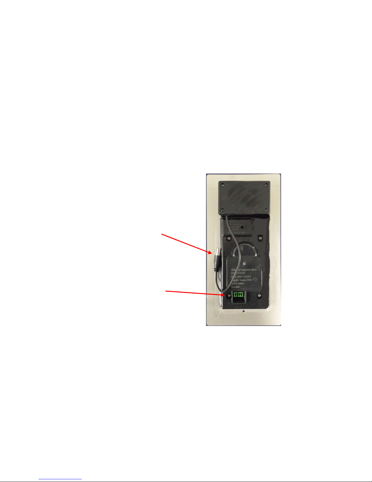
The Integrated Camera is powered direct from the Door Phone, which receives its
power via the 4 wire connection from the DS Controller.
The power consumption of the Camera is approximately 150 mA and this
cannot be supported over distances greater than 75 yards.
BNC Video Output
DS Controller Input
Page 8 Natcomm
Page 9

CAMERA WIRING
DP4 provides a BNC output for Video, which can be connected to standard TV’s,
dedicated Video display units or both.
If IP Video is required, the DP4 video output should be connected to an Analogue to
Video IP Converter. A recommended device is the AXIS 241S.
You can use either Coaxial cable or CAT5 cable to connect video to your Video
display units.
As only 4 wires of an 8 wire CAT5 cable are required for the Door Phone, 4 wires
are unused, unless One or Two Door locks are used in conjunction with the Door
Phone.
If only One Door Lock is used, then 2 wires are still available for Video.
If Two Door Locks are used, there will be no spare wires and a separate CAT5 cable
or a Coaxial cable will be needed for Video.
If you plan to use 2 wires of a CAT5 cable, then you will need to use a pair of CAT5
Video Baluns to transfer the video signal. One Balun will connect to the BNC output
from the DP4 and the other will connect to your Video display device. A single pair
of the CAT5 cable is then used between the Baluns.
Good Quality Baluns will allow for good quality video over 75 Yards of CAT5 cable.
CAT5 Video Baluns
Natcomm Page 9
Page 10
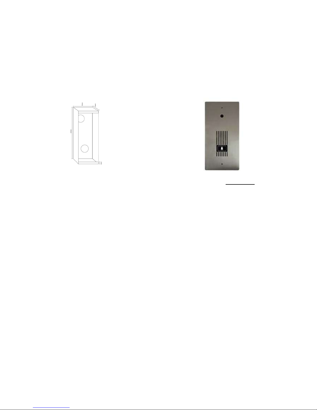
MOUNTING THE DOOR PHONE
The DOOR PHONE should be mounted at the average face
height of 1.5 meter (5 feet) for optimum performance.
The main body of the DP4 unit is designed to be recessed into a wall surface, unless
you use the Optional Surface Mounting Kit (see below).
A recess area of:
10.0 in x 3.7 in x 1.6 in (D)
or
255 mm, 93mm and 40mm (D)
should be prepared for insertion
of the Wall Mount Box.
To assist installation, a Galvanized Iron ‘Wall Mount box’ (WMB) is supplied, to be
fitted within the wall cavity.
You should first place the WMB on your wall surface and trace around it with a
pencil or a fine pen. This outline will then determine the ‘cut out area’ you will need
and where you should make your cuts into the wall surface.
The Wall Mount Box should then be securely fixed within the recessed cavity using
nails, dyna bolts or silicone.
DP4 should then be screwed onto the WMB using the 2 supplied stainless steel
screws. This results in very secure mounting for your DP4.
SURFACE MOUNTING KITS
Optional Stainless Steel Surface Mounting Kits are available for all Natcomm Door
Phones, so that your Door Phone can be mounted ONTO a wall surface, rather than
into it. See page 18 for further detail.
Page 10 Natcomm
Page 11

OPERATION
After initial Power Up, the Door Phone will take up to 5 seconds to initialize.
To commence a Door Phone call, you should press the BELL on the Door Phone
briefly. The LED will then turn OFF and you will hear a RING TONE until the call is
answered.
This Door Phone will trigger a Door Station Controller that will either RING all the
telephones connected to your telephone line or it will operate with a PBX system.
As soon as the call is answered, you will be able to communicate with clear call
quality.
If this Door Phone is connected to a Model DS3 Controller, you will also have the
ability to connect to an external telephone number, or cell phone whenever the site
is unattended.
After your Door Phone call is completed, there will be a delay of approximately 5
seconds before the unit has reset and is ready for the next call.
Our Door Phones use an intelligent, fast switching ‘half duplex’ communication
method, as this provides for highest volume levels and eliminates feedback in areas
with low to moderate background noise levels.
Note : This method is not suitable for areas where high background noise levels are
present as the Door Phone will not be able switch back to the quiet indoor areas
properly. A balance pot adjustment may be needed in areas with some background
noise.
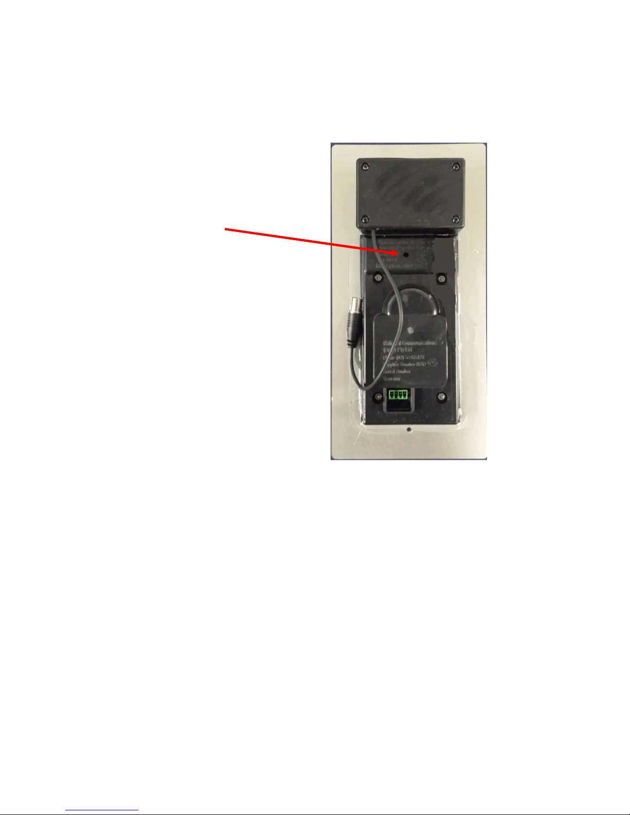
The Door Phone Balance Pot is located behind a sealing plug on the rear of DP4.
Its position is Factory Set and will usually not have to be adjusted. For some
installations (such as when using 2 Door Phones in parallel), it may be necessary to
adjust the Balance Pot (see pages 12-13).
WHEN TESTING YOUR DOOR PHONE, DO NOT USE A TELEPHONE IN
CLOSE PROXIMITY AS FEEDBACK WILL CAUSE LOSS OF VOLUME
Natcomm Page 11
Page 12
BALANCE POT ADJUSTMENT
The Balance Pot is located under
a sealing plug here:
In the unlikely case you need to
make an adjustment, you will
need to use a small flat blade
screwdriver.
Move clockwise or anti-clockwise
in small increments and check for
improving or worsening audio.
Then keep adjusting in the
improving direction until good
quality Audio is achieved in both
directions.
Page 12 Natcomm
Page 13

BALANCE POT ADJUSTMENT
Your DOOR PHONE is preset at the factory for maximum performance.
Our sophisticated circuitry is designed to measure the background noise present at
your site and then apply maximum gain.
In almost all cases you SHOULD NOT NEED TO MAKE ANY ADJUSTMENTS.
If you are using Two Door Phones, it is possible that you will need to adjust the
POT of one or both Door Phones to suit your specific site conditions.
The balance POT is provided in case you experience one of the following:
Audio is distorted.
Audio (speech) can only be heard in 1 direction.
Should you encounter one of these problems, you will need to make slow careful
adjustments in one direction or the other until speech can be heard in both
directions and without distortion.
The balance POT is located on the back of DOOR PHONE under a small 3mm
removable black plastic plug. It should be adjusted using a small flat blade
screwdriver.
IMPORTANT NOTES
1)
You will require TWO PEOPLE to adjust your Door Phone Pot.
2)
Wait 10 seconds after answering before adjusting the Pot.
3)
DO NOT use a telephone in close proximity to the door phone, as
feedback interference will affect the Balance Pot settings.
4)
The Balance POT does not increase volume. Moving it when
unnecessary may cause deterioration in audio quality or a loss of audio in
1 direction.
Natcomm Page 13
Page 14
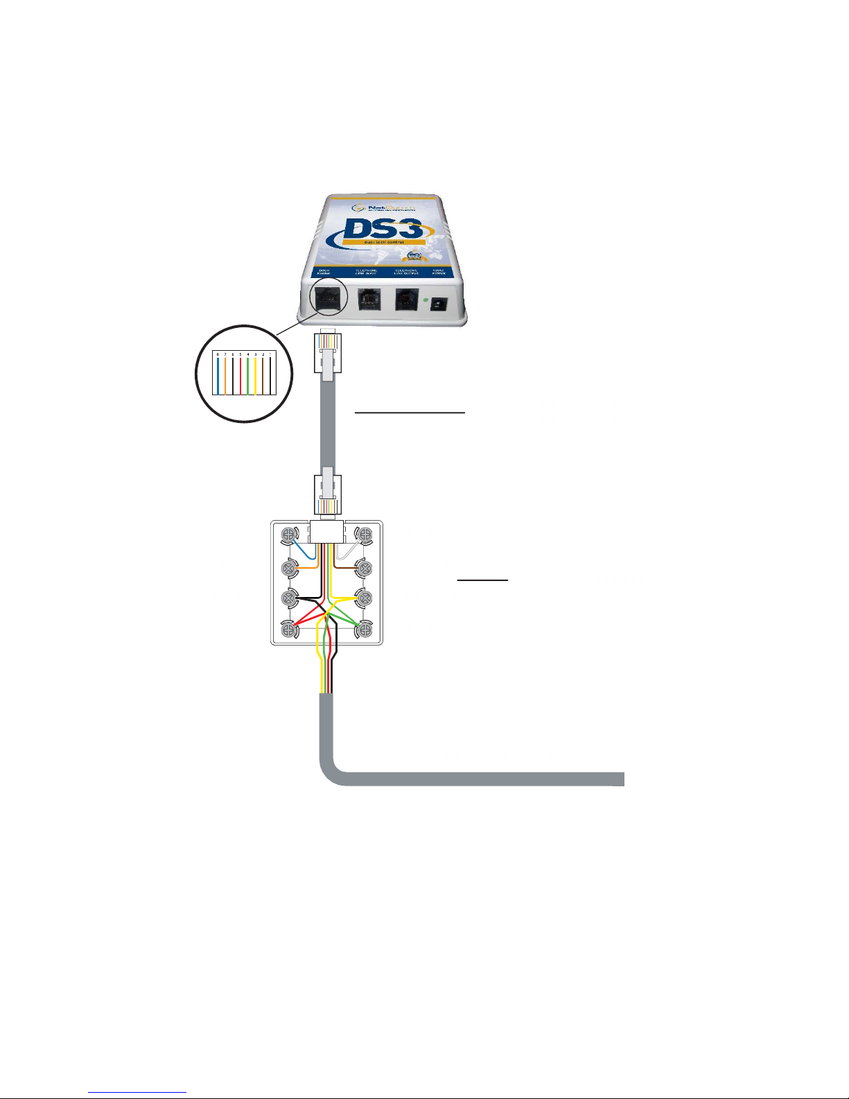
CONTROLLER WIRING
connection cable
SUPPLIED CABLE
BLUE LOCK 2
LOCK 2 WHITE
ORANGE LOCK 1
LOCK 1 BROWN
BLACK POWER
POWER YELLOW
RED AUDIO
AUDIO GREEN
power supplies
CAT5
CABLE or SOLID CORE CABLE
Supplied 8 wire
Supplied 8 wire
connection box for
connection of
1 or 2 Lock Release
Page 14 Natcomm
Page 15
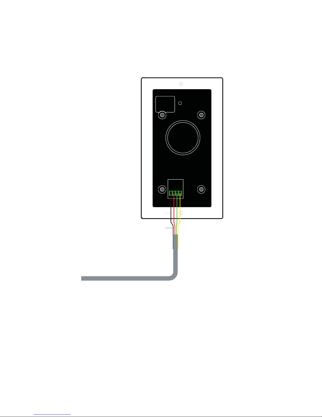
DOOR PHONE WIRING
BLACK
POWER
RED
AUDIO
CAT5 CABLE or SOLID CORE CABLE
POWER
AUDIO
YELLOW
GREEN
The colors used are those of the wires in the supplied Interface box.
Natcomm Page 15
Page 16
WIRING CONNECTION
Solid core cable such as CAT5 should be used to connect between the DS Controller
unit and the Door Phone unit. The DS Controller unit has a standard 8 wire RJ45
connector. The Door Phone uses a 4 position Dinkle plug (EC350V-04P).
Four wires are used to connect the Door Phone to the DS Controller unit. Two wires
are required for each internal relay used for Lock control. A maximum of 8 wires is
required for installation, so a CAT5 cable is ideal
An external connection box with 8 screw terminals is supplied with your DS
Controller unit. The connection box provides a convenient means of connecting the
2 or 4 wires used for 1 or 2 Gate or Door locks to the internal relays of the DS
Controller. The connection box connects to the DS Controller unit via the supplied
short RJ45 cable. If Lock control is not required, you will not need to use this box.
Where LOCK CONTROL is not required, you can bypass the connection box and
connect your CAT5 cable direct to the DS Controller. For details see page 17.
There is a 4 position Dinkle press in connector socket on the rear of the Door Phone,
to which you connect the Audio and Power wires.
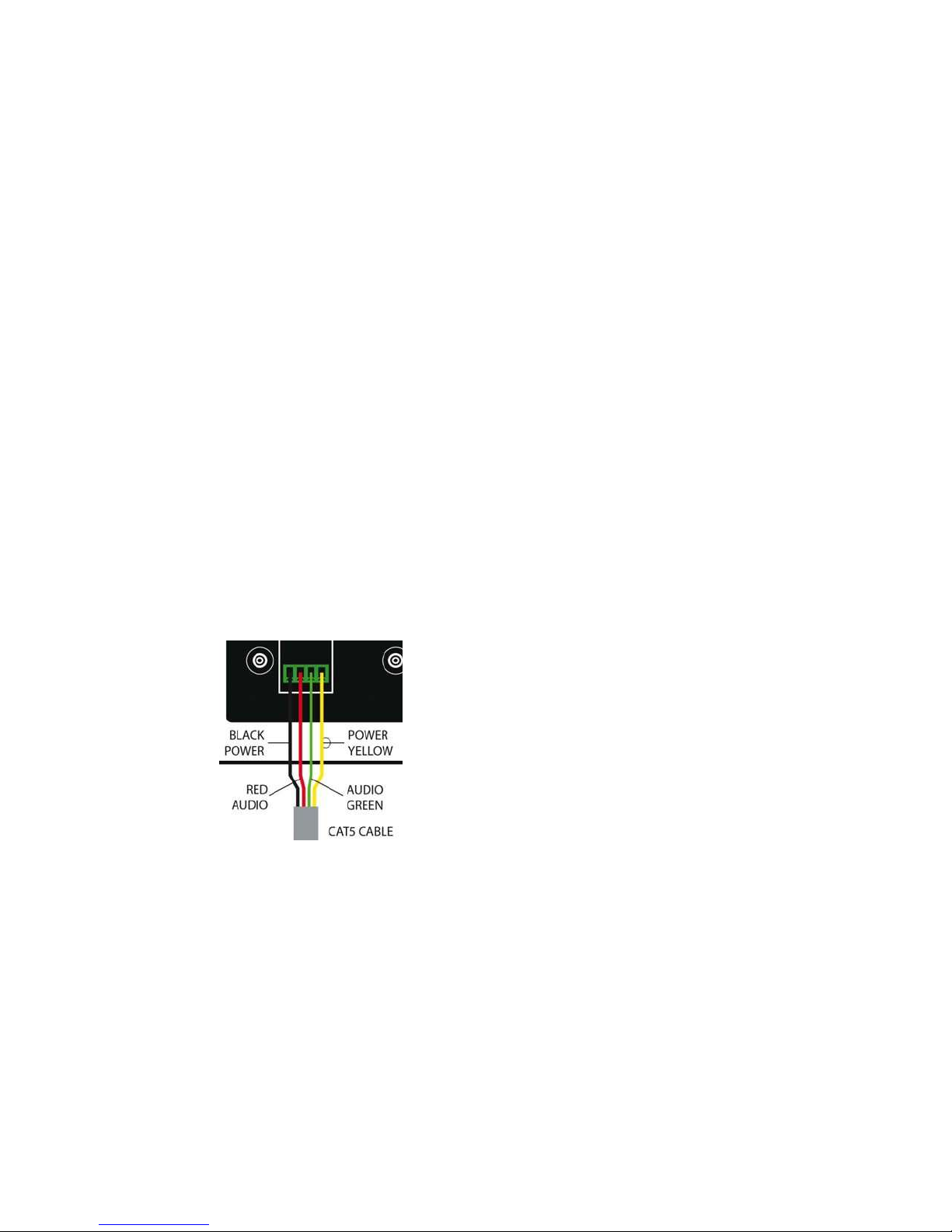
Two wires are required for the AUDIO
SIGNAL and Two wires are used to
provide POWER to the unit.
The Audio signal connects to the middle
Two positions of the socket.
The Power input connects to the outside
Two positions of the socket.
Note: The polarity of the Audio signal and
power connections is not important and
can be reversed.
Page 16 Natcomm
Page 17

The RED WIRE of the connection box carries one leg of the Audio Signal. It
must connect to EITHER center position (pin 2 or 3) of the supplied Phoenix
plug. Note - Polarity is not important.
The GREEN WIRE of the connection box carries the other leg of the Audio
Signal. It must connect to EITHER center position (pin 2 or 3) of the supplied
Phoenix plug. Note - Polarity is not important.
The BLACK WIRE of the connection box carries one leg of the 12V Power
input. It must connect to EITHER outer position (pin 1 or 4) of the Phoenix
plug. Note - Polarity is not important.
The YELLOW WIRE of the connection box carries one leg of the 12V Power
input. It must connect to EITHER outer position (1 or 4) of the Phoenix plug.
Note - Polarity is not important.
Where Two Door Phones are to be used, they should both connect to the same
contacts of the interface box (ie: parallel connection).
The ORANGE and BROWN WIRES of the connection box connect to the
Internal Relay used for Lock 1. Connect ONE leg of the 12V power for Lock 1
to these terminals, by cutting the wire in half and fit one part to the screw
terminal connecting to the Orange wire and the other to the screw terminal
connected to the Brown wire. Polarity is not important.
The BLUE and WHITE WIRES of the connection box connect to the Internal Relay
used for Lock 2. Connect ONE leg of the 12V power for Lock 2 to these terminals,
by cutting the wire in half and fit one part to the screw terminal connecting to the
Blue wire and the other half to the screw terminal connected to the White wire.
Polarity is not important.
BYPASS CONNECTION BOX
If you don’t plan to use the connection box, then you can connect the
CAT5 cable direct to the DS Control unit and Door Phone, as follows:
AUDIO CONNECTION (polarity is not important)
The center 2 pins of the DS Controller RJ socket need to
connect to the center 2 positions of the DP2 Dinkle socket.
POWER CONNECTION (polarity is not important)
The 2 pins either side of the center 2 pins of the DS Controller socket
connect to the 2 outer positions of the 4 pin Dinkle socket.
Natcomm Page 17
Page 18
SURFACE MOUNTING KITS
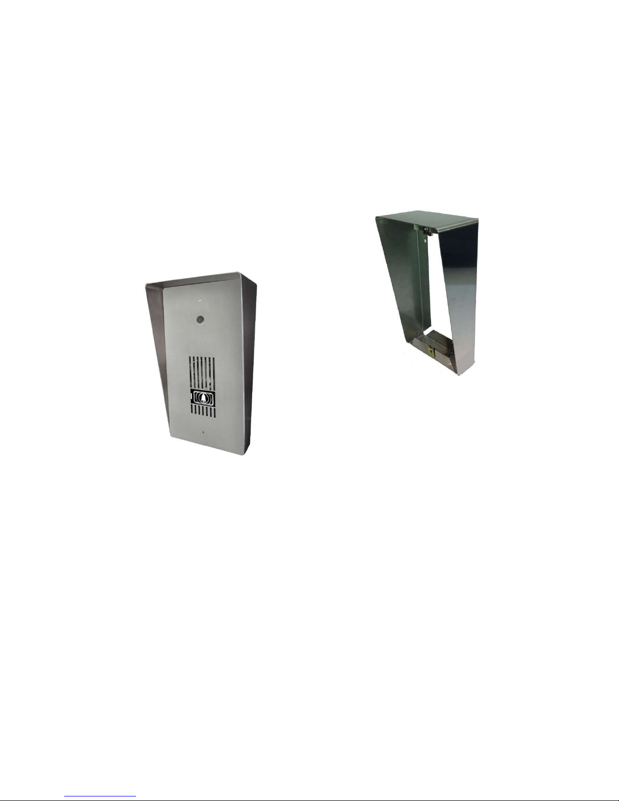
Stainless Steel Surface Mounting Kits are available for all Door Phones, so that your
Door Phone can be mounted ONTO a wall surface, rather than into it.
Two separate surface mounting kits are available, to cater for the two different sized
Door Phones (DP2-DP5) that can be mounted vertically.
All kits have an integrated Rain Deflector.
Model SMK3 : for DP4, DP5
Note : This picture displays
an earlier generation DP4
FCC (USA) and IC (Canada) COMPLIANCE
This product has been tested by an authorized independent laboratory to comply
with all Telephone Line and Electromagnetic Compliance requirements for the USA
and Canada.
Please refer to the separate page supplied with this product for further important
information.
Page 18 Natcomm
Page 19
DOOR PHONE COVER
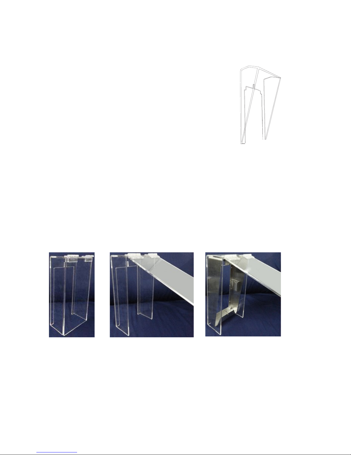
If your Door Phone is not under cover, a strong
transparent DOOR PHONE COVER is essential to
ensure that water from rain cannot gradually
permeate through to the electronics of the Door Phone
which can cause unreliable operation and can
eventually lead to permanent failure of this device.
Model DPC3 : for the Model DP4 Door Phone
EXTREME WEATHER COVER
Wherever a Door Phone is exposed to Extreme Weather Conditions such as :
Located in the open in areas where there is Very High Rainfall with Wind
When located very close to the ocean or salt water
It is HIGHLY recommended that you use our Extreme Weather Cover (Model
XWC3). This cover is made from Strong 0.2’ (5mm) Transparent Perspex and
fitted with a Hinged Front Face which is lifted when the Door Phone is to be used
and will return to its closed position when the Door Phone is complete.
The Hinge Door can be rotated beyond 180 degrees, allowing it to open up and
lean against the wall or post. In this situation, it should then be returned to its
normal position when the Door Phone use is complete.
Natcomm Page 19
Page 20

SPECIFICATIONS
Dimensions (inches) : 10.4 (H) 5.1 (W) 1.5 (D)
Dimensions (mm) : 264 (H) 130 (W) 37 (D)
Weight : 1.1lb or 500g
Audio & Power Connector : Dinkle EC350V-04P
Video Output Connector : BNC
FCC & IC COMPLIANT : Supplier Number NC
ACMA COMPLIANT : Supplier Number N 78
WARRANTY
This device is guaranteed against defects from workmanship for a period of two
years (24 months) from the date of purchase.
In the event of a problem, please call ph 800 530 8645 for assistance and if
necessary, a Return Authorization. You should then return your unit, along with the
proof of purchase date, and a written statement about the nature of the problem.
The Manufacturers obligation is solely to repair or the product. The product may be
replaced at the discretion of the Manufacturer. The warrantor is not liable for any
incidental or consequential damages due to such defects.
This Warranty shall not apply to any unit which has been subject to alteration,
modification, abuse, negligence, accident, external voltage/ lightning surge or used
in any manner contrary to these instructions.
The user is responsible for freight costs to the repair point. The warrantor will be
responsible for freight costs in returning this unit back to the user.
Damage caused to this device or attached equipment by lightning strikes or over
voltage surge is not covered under this warranty.
THE CASE IS SEALED AT THE FACTORY.
OPENING THE CASE WILL VOID THE WARRANTY.
Page 20 Natcomm
 Loading...