

Page 1
DMS
USER GUIDE
For Technical Assistance
Please Phone: (07) 5596 5128
September 2015
Page 2
Page 2 National Communications
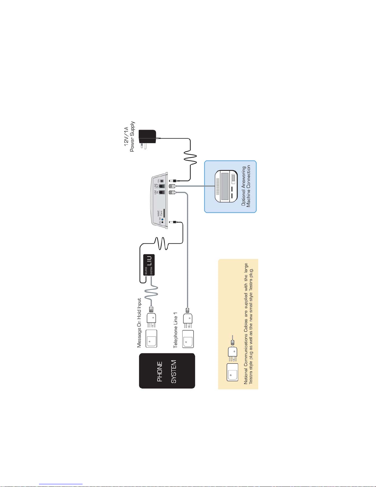
INSTALLATION DIAGRAM
Page 3

PRODUCT DESCRIPTION
Our DMS Digital Message Player, is designed to connect to a PABX or other
Multi-Line T elephone System to provide :
• A High Quality Message On Hold facility.
and
• A High Quality After Hours Announcement.
This means that in addition to a High Quality MESSAGE ON HOLD facility,
you can now provide a STUDIO QUALITY After Hours announcement to all
callers when your office is closed and this message can be of any length. At
the end of your announcement, DMS can then either :
• HANG UP
or
• RING YOUR ANSWERING MACHINE (Default Mode)
so your callers can leave a Message
There is an ANSWER ON/OFF Touch Switch located on the front face. T ouching
this switch once, will turn the Answering Facility ON (Red Light will turn ON).
Y ou should do this when leaving the office. Touching it again will turn the After
Hours Answering Announcement facility OFF (Red Light will turn OFF). You
should do this when arriving at the office.
ATTENDED OFFICE OPERATION
Red Light should be OFF
DMS will provide a MESSAGE ON HOLD feed to your T elephone System.
AFTER HOURS OPERATION
Red Light should be ON
DMS will ANSWER your INCOMING CALLS, play your After Hours
ANNOUNCEMENT MESSAGE and then Hang Up or Ring an Answering
Machine attached to it if you wish to allow your callers to leave a Message.
National Communications Page 3
Page 4

Page 4 National Communications
ANSWERING MACHINE OPERATION
DMS is set by DEFAULT to operate WITHOUT an Answering Machine.
This means that it will HANG UP immediately once the Announcement
Message has been completed..
DMS is set by DEFAULT to operate WITHOUT an Answering Machine.
DMS can also operate with your ANSWERING MACHINE so that your
callers can leave a Message.
If you wish to utilise this capability , you should connect your Answering Machine
to the LINE OUT port of DMS, as described on pages 10-1 1.
DMS will then RING your Answering Machine at the completion of your
Announcement Message.
TO SET : DMS TO OPERATE WITH AN ANSWERING MACHINE
enter #410 when in the programming mode
See page 15, Section D 2 for more details
Important Notes
1) You should turn your Answering Machine ON and leave it ON at all times.
2) You should set your Answering Machine to answer as quickly as possible,
to minimize the delay between the end of your Announcement and the beginning
of the Out-Going Message of your Answering Machine.
3) As it is always necessary for an Answering Machine to have an Out-Going
Message, you should record a short instruction on the Answering Machine
such as :
“Please leave your message after the BEEP “.
Page 5
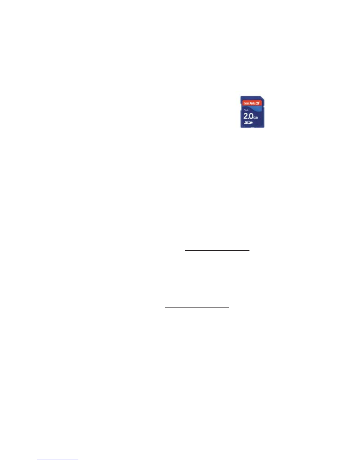
SD FLASH CARD
DMS is supplied with an 2GB (or greater) SD Flash
Card to store the MP3 based messages that it should
play.
Two MP3 files need to be loaded onto the Flash Card.
One MP3 File is used for the P ABX ‘On Hold Message’.
One MP3 File is used for the P ABX ‘After Hours Message’.
DMS must be able to differentiate the Two files that have been loaded
onto the SD card and it does this by looking at the file name.
DMS differentiates the Two files by looking for the number of the first 3
digits of MP3 filenames.
The Filenames of the MP3 Files used with DMS must be named as
follows :
One MP3 file is for the ANNOUNCEMENT MESSAGE.
NOTE - The filename of this message MUST START WITH 001, so that
DMS knows that this Message is to be used for announcements.
example : 001XYZcompanyannouncement.MP3
The other MP3 file is for the ON HOLD MESSAGE.
The filename of this message MUST ST ART WITH 002 (or any number
up to 019), so that DMS knows that this Message is to be used for On
Hold use.
example : 002XYZcompanyonhold.MP3
If your DMS IS fitted with the OPTIONAL Message File Time
Programming facility, refer to the information on p age 6.
If your DMS IS NOT fitted with the OPTIONAL Message File Time
Programming facility , please proceed to page 8.
National Communications Page 5
Page 6

Page 6 National Communications
TIME PROGRAMMABLE FILES
If your DMS IS fitted with the OPTIONAL Message File Time Programming
facility , then you can load :
* Up to a Maximum of FIVE Separate ‘On Hold Messages’
* Up to a Maximum of FIVE ‘After Hours Messages’.
Each of the Maximum of TEN ‘Messages’ can be programmed to play at :
* Different Times of the Day
* Different Days of the Week
* Between Preset Date Periods
1. The ‘Announcement Messages’ must be numbered with filenames
beginning with 001, 002, 003, 004 and 005. Y ou can up to FIVE :
001XYZcompanyannouncement.MP3
002XYZcompanyannouncement.MP3
003XYZcompanyannouncement.MP3
004XYZcompanyannouncement.MP3
005XYZcompanyannouncement.MP3
2. The ‘On Hold Messages’ must be numbered with filenames beginning
with 006, 007, 008, 009 and 010. You can up to FIVE :
006XYZcompanyonhold.MP3
007XYZcompanyonhold.MP3
008XYZcompanyonhold.MP3
009XYZcompanyonhold.MP3
010XYZcompanyonhold.MP3
3. Load All Mesaages onto the SD Card in strict numeric order .
4. Install the DMC Control Program as per the separate ‘Time
Programmable Message Change User Guide also supplied with this option.
5. Program Each File with the required Play Times, Days or Date Periods,
using the DMC Control Program supplied on the enclosed CD.
Important Note : Only 1 ‘After Hours Message’ and 1 ‘On Hold Messages’
can be programmed play at any 1 time. If more than 1 of either type of
Message is set to play at the same time, then only the filename with the
lowest 3 digit filename prefix will play.
Page 7

National Communications Page 7
INSTALLATION - OVERVIEW
There are TWO stages involved in the installation of your DMS device.
1) MESSAGE ON HOLD - INSTALLATION
This involves connecting DMS to a Telephone System On Hold Port,
using a Line Isolation Unit.
Please refer to pages 8-9
2) AFTER HOURS ANNOUNCEMENT - INSTALL
This involves connecting DMS in place of an Answering Machine
OR
If an Answering Machine has not been used previously, DMS will
need to be connected in parallel to LINE 1 of the Telephone System.
Please refer to pages 10-1 1
Important Note
DMS should be connected in
parallel with Line 1
Page 8

Page 8 National Communications
MESSAGE ON HOLD - INSTALLATION
Where an existing RADIO, CD or T APE player
is being replaced
1. Disconnect Power to the existing audio device.
2. Disconnect the Audio Output Cord of the existing Line
Isolation Unit (LIU) from the existing audio device.
Note - An LIU (Line Isolation Unit) is used to connect Audio
from the AUX or HEADPHONE outlet of the existing device
through to the telephone system.
This is an ACMA safety requirement.
3. Connect the Audio Output Cord of the existing LIU to the
3.5mm Audio Output connector of your DMS unit.
Note - If the existing LIU does not use a 3.5mm Audio Plug,
then you will need to replace the existing LIU with a new
LIU which has a 3.5mm Audio Plug. These are available
from National Communications (ph 07 55965128).
4. Power Connection
A 12VAC/1A power adaptor is supplied with your unit. This
must be connected to an electrical power outlet, which is
switched ON.
5. Message Volume Adjustment
Place a call to the telephone system, put the call ON HOLD
and adjust the volume to a suitable level using the volume
pot located on the rear of DMS. Turning the POT clockwise
will increase the volume.
Page 9

National Communications Page 9
MESSAGE ON HOLD - INSTALLATION
Where an existing RADIO, CD or T APE player
IS NOT being replaced
1. An ON HOLD connection port is required for the connection
of an Audio Source to the Telephone System. This connection is
normally a 610 Style Telephone Socket (ie the old style Australian
telephone socket) or a Modular Style Telephone Socket (ie the
new style Australian telephone socket).
Note : If the Telephone System is NOT fitted with an ON HOLD
connection port, then you will need to arrange for an ACMA
qualified Telephone Technician to fit one. The contact details
of suitable technicians, in most areas, are available by
contacting National Communications on (07) 55965128.
2. An LIU (Line Isolation Unit) fitted with the appropriate telephone
plug connection and a 3.5mm audio connector must be used to
connect the audio output from your DMS unit to the ON HOLD
input port of your telephone system. This is an ACMA safety
requirement.
Note : Some Telephone Systems may use an RCA or a 3.5mm
audio socket for their ON HOLD connection port. If this is the
case, you will need to use an LIU fitted with the appropriate
plug. LIU’s with all connection types are available by contacting
National Communications on (07) 55965128.
3. Connect the Audio Output port of DMS to the Telephone
System ON HOLD connection port, using the LIU.
Note : If Audio from DMS cannot be heard when calls are placed
On Hold, then your Telephone System may need to be
programmed to advise it that a MESSAGE on HOLD facility
has been fitted to it. You should contact your Telephone System
supplier for assistance.
4. Power Connection
A 12VAC/1A power adaptor is supplied with your unit. This must
be connected to an electrical power outlet, which is switched ON.
Page 10

Page 10 National Communications
ANNOUNCEMENT - INSTALLATION
Where an existing ANSWERING MACHINE is being replaced
1. Disconnect Power to the existing Answering Machine.
2. Remove the Telephone Cable which is connected to the existing
Answering Machine, from the socket where it connects to it.
3. Connect the Telephone Cable (removed above) to the LINE
IN port located at the rear of DMS.
Please Note : If the Answering Machine is still required to record
incoming messages, then you should connect it to the LINE OUT
port located at the rear of DMS.
4. Power Connection
A 12VAC/1A power adaptor is supplied with your unit. This must be
connected to an electrical power outlet, which is switched ON.
5. Announcement Message Volume Check
Turn On the Announcement facility by pressing the Button located
on the top face of DMS.
Place a call to the telephone system by dialing your normal telephone
number. DMS will then ANSWER your call and play your
Announcement Message before hanging up (note - DMS will take
approx 15 seconds before hanging up, as it is programmed by default
to ring an Answering Machine that may be connected to the Line Out
port.
If the volume is too high or too low, you can adjust the volume to a
suitable level using the volume pot located on the rear of DMS.
Turning the POT clockwise will increase the volume.
Note - Changing the volume will also change the volume of the
ON HOLD MESSAGE as well, so you will need to set a volume
which is suitable for both Message Applications.
DMS should be connected in parallel with Line 1
Page 11

National Communications Page 11
ANNOUNCEMENT - INSTALLATION
Where an existing ANSWERING MACHINE is NOT being replaced
1. An ANSWERING MACHINE connection port is required to allow
the DMS device to ANSWER your After Hours calls. This
connection is normally a 610 Style Telephone Socket (ie the old
style Australian telephone socket) or a Modular Style Telephone
Socket (ie the new style Australian telephone socket).
Note : If the Telephone System is NOT fitted with an ANSWERING
MACHINE connection port, then you will need to arrange for an ACMA
qualified Telephone Technician to fit one. The contact details of
suitable technicians, in most areas, are available by contacting
National Communications on (07) 55965128.
2. Connect the ANSWERING MACHINE socket to the LINE IN port
located at the rear of DMS using the supplied cable.
Note : If an Answering Machine is required to record incoming
messages, then you should connect it to the LINE OUT port
located at the rear of DMS.
3. Power Connection. A 12VDC/1A power adaptor is supplied with your
unit. This must be connected to an electrical power outlet, which is
switched ON.
4. Announcement Message Volume Check. T urn On the Announcement
facility by pressing the Button located on the top face of DMS. Place
a call to the telephone system by dialing your normal telephone
number. DMS will then ANSWER your call and play your
Announcement Message before hanging up.
If the volume is too high or too low, you can adjust the volume to a
suitable level using the volume pot located on the rear of DMS. Turning
the POT clockwise will increase the volume.
Note - Changing the volume will also change the volume of the ON HOLD
MESSAGE as well, so you will need to set a volume which is suitable
for both Message Applications, or you will need to also use the volume
adjustment on the supplied Line Isolation Unit (LIU).
DMS should be connected in parallel with Line 1
Page 12

Page 12 National Communications
MESSAGE ON HOLD OPERATION
Once Power is connected and an SD card with both MP3 files is inserted
into its Flash Card slot, DMS will begin supplying your MESSAGE ON
HOLD message to your Telephone System. It will play the Announcement
Message first (once only) before proceeding to ‘loop’ the On Hold
Message.
Whenever power is reconnected to the unit, or another SD card is
inserted into the unit, DMS will undergo an approximate 10 second
‘Initialisation or Boot Up process’. During this time, DMS will carry out
a series of self diagnosis procedures where it will check the SD Card,
Power Supply and other important areas. It will then play the
Announcement Message first (once only) before proceeding to ‘loop’
the On Hold Message.
ANNOUNCEMENT OPERATION
TO TURN THE ANNOUNCEMENT ON
To set DMS to Automatically ANSWER all INCOMING CALLS on your
Main Telephone Line (Line 1) and then play your AFTER HOURS
ANNOUNCEMENT MESSAGE :
Press the TOUCH SWITCH located on the front panel so that the :
RED LIGHT IS ON
TO TURN THE ANNOUNCEMENT OFF
To set DMS to NOT ANSWER your INCOMING CALLS :
Press the TOUCH SWITCH located on the front panel so that the :
RED LIGHT IS OFF
Page 13

National Communications Page 13
PLAYBACK CHECK OPTION
DMS can be OPTIONALLY fitt ed with an Internal Speaker which is used
as part of our Play Back Check facility.
When this option is fitted, DMS outputs it’s Audio Message to the
Telephone System, via the LIU, whenever the LIU is connected.
DMS will connect it’s Audio Message to the Internal Speaker whenever
the LIU is not connected
This facility means that the user can quickly and easily confirm whether
the unit is playing its MP3 message, by simply removing the LIU plug
from the rear of the unit.
TO CHECK YOUR UNIT IS PLA YING A MESSAGE
Remove the Audio Connection from the AUDIO OUT port on the back of
your unit.
If you can hear your message through the speaker located within DMS,
everything is fine and you can now re-insert the Audio Connection to the
AUDIO OUT port on the back of your unit.
If you CANNOT hear your message through the speaker located within
DMS :
1) Check or change your power connections until the AUDIO starts to
play (Note - after power connection, there is a 10 second delay before the
Message will begin to play.)
2) If the Message does not start to play after the 10 second delay, check
that your SD Flash Card is inserted correctly by removing it and then
replacing it into the SD Flash Card slot located on the back of your unit.
3) If it is still not playing, call your Dealer for assistance.
Page 14

Page 14 National Communications
PROGRAMMING OPTIONS
DMS provides for THREE USER PROGRAMMABLE SETTINGS which
will allow you to customise the capability of this device to meet individual
requirements.
User SETTINGS are stored in flash memory which will retain your settings
even if power is disconnected.
In most cases the DEFAULT SETTINGS of this device will be suitable
for your requirements.
Y ou should only change the DEFAULT SETTINGS after carefully reading
the detailed information for PROGRAMMING detailed on pages 14-15.
To program DMS, you must temporarily connect a standard analogue
telephone to the Line Out port, as Program Changes are made by using
‘touch tone’ keys.
THE DEFAULT SETTINGS OF THIS DEVICE ARE :
1. DMS will ANSWERS CALLS IN 2 RINGS.
You can change this to 1-20 Rings.
2. DMS will NOT RING the LINE OUT port after playing its message.
If you plan to use an Answering Machine, you MUST program DMS to
RING the LINE OUT after playing its message.
This RING will cause an Answering Machine to Answer after the
Announcement is played so that an incoming caller can leave a
message.
You must set your Answering Machine to answer calls in less than 5
rings, as DMS will hang up after the 5th ring. You should set the
Answering Machine to answer on the minimum ring setting.
If an Answering Machine is not to be used, you can set this p arameter
to 0 to cause the unit to hang up immediately after it finishes the
announcement.
Page 15

National Communications Page 15
PROGRAMMING PROCEDURE
You MUST connect a standard analogue (residential type) telephone to the
Line Out port of DMS to carry out programming via the touch tone keys.
A. TURN OFF POWER TO YOUR UNIT
B. SWITCH ON POWER AND PRESS # (within 30 seconds)
On the attached telephone that has been temporarily connected
for programming.
C. YOUR UNIT WILL OUTPUT 3 SHORT ‘BEEPS’
Do not proceed until you have heard 3 short beeps.
If you do not hear 3 beeps, return to the start (A).
D. ENTER PROGRAMMING CHANGES AS FOLLOWS:
(Y ou can change one or more parameters in any order)
1. RING COUNT BEFORE ANSWER
To enter the NUMBER OF RINGS press #1xx (on the telephone)
where xx = number of rings and can be 00-19
T o Answer in 2 rings, press #102 (Default)
T o Answer in 8 rings, press #108
Please wait for confirmation beep before proceeding.
2. PROGRAM ANSWERING MACHINE OPERA TION
T o Program DMS to operate with an Answering Machine
Press #410 (on the telephone)
T o Re-program DMS to NOT operate with an Answering
Machine
Press #400 (on the telephone)
Please wait for confirmation beep before proceeding.
TO LEA VE PROGRAMMING MODE, SIMPLY HANG UP.
Page 16

Page 16 National Communications
SPECIFICATIONS
Dimensions : 165w x 150d x 60h mm
Weight : 415g
Power Supply : 240VAC to 12V AC/500mA
Power Consumption : Idle - 100mA
: Ringing - 230mA
Ringer Equivalence : 0.3 REN
Connectors : RJ 11 6 pin (2 centre)
: 2.5mm barrel connector
ACMA COMPLIANCE : N 782
WARRANTY
This device is guaranteed against defects from workmanship for a period
of two years (24 months) from the date of purchase. In the event of
failure, you should return the product, along with proof of purchase date,
and a written statement about the nature of the problem.
This Warranty shall not apply to any unit which has been subject to
alteration, modification, abuse, negligence, accident, external voltage/
lightning surge or used in any manner contrary to these instructions.
The obligation is solely to repair or replace the product. The warrantor
is not liable for any incidental or consequential damages due to such
defects.
The user is responsible for freight costs to the repair point. The warrantor
will be responsible for freight costs in returning this unit back to the
user.
Damage caused to this device or attached equipment, by lightning strikes
or over voltage surge is not covered under this warranty .
CASE SEALED AT FACTORY
OPENING THE CASE VOIDS THE WARRANTY
 Loading...