

Page 1
Thank you for purchasing a Nashbar Trainer. The Nashbar Fluid trainer provides smooth, quiet and adjustable resistance to meet the
demands of any workout.
PARTS LIST:
PART PART CODE
Trainer Frame .............................................................A ..........
Resistance Unit ..........................................................B ..........
Base Plate ...................................................................C ..........
Lever Handle ...............................................................D ..........
Load Lever ..................................................................E ..........
Control Knob ...............................................................F ..........
Left Axle Support Cup .................................................G ..........
Right Axle Support Cup ...............................................H ..........
Resistance Unit Bolts and Washers ............................ I ...........
Base Plate Bolt, Nut and Washers ..............................J ..........
Frame Leg Bolt, Washer, Nut, Nut Cover ......................K ..........
Frame Leg Plastic End Caps ......................................L ..........
Quick Release (QR) Skewer ...................................... M ..........
5mm Hex Wrench ................................................not shown ...
FLUID TRAINER
• This trainer is intended for single-rider bicycles only.
• Read and follow all instructions.
• Before beginning each workout, be sure bicycle is securely attached to the trainer.
•
During use, resistance unit can become hot enough to cause burns. Do not touch resistance unit during or after use,
untilithashadsufcienttime tocool.
• Keep children and pets away from the trainer during use.
• Consult a physician before beginning any exercise program.
WARNING
For Technical support, call 1-800-888-2710 0513-1 BN-NFLD Made in ItalyFor Technical support, call 1-800-888-2710 0513-1 BN-NFLD Made in Italy
Read and follow all instructions concerning installation of bicycle on trainer. Failure to use supplied quick release skewer or to
securely attach bicycle to trainer could result in the bicycle falling, causing injury to rider or bystanders.
WARNING
E
C
TIRE
B
ROLLER
Fig 20
Fig 24 Fig 25
F
E
C
Fig 22
Fig 26
Fig 23
C
B
I
Fig 21
ASSEMBLY: (Note: In this manual, "Left" and "Right" are
from the perspective of a rider seated on the bicycle.)
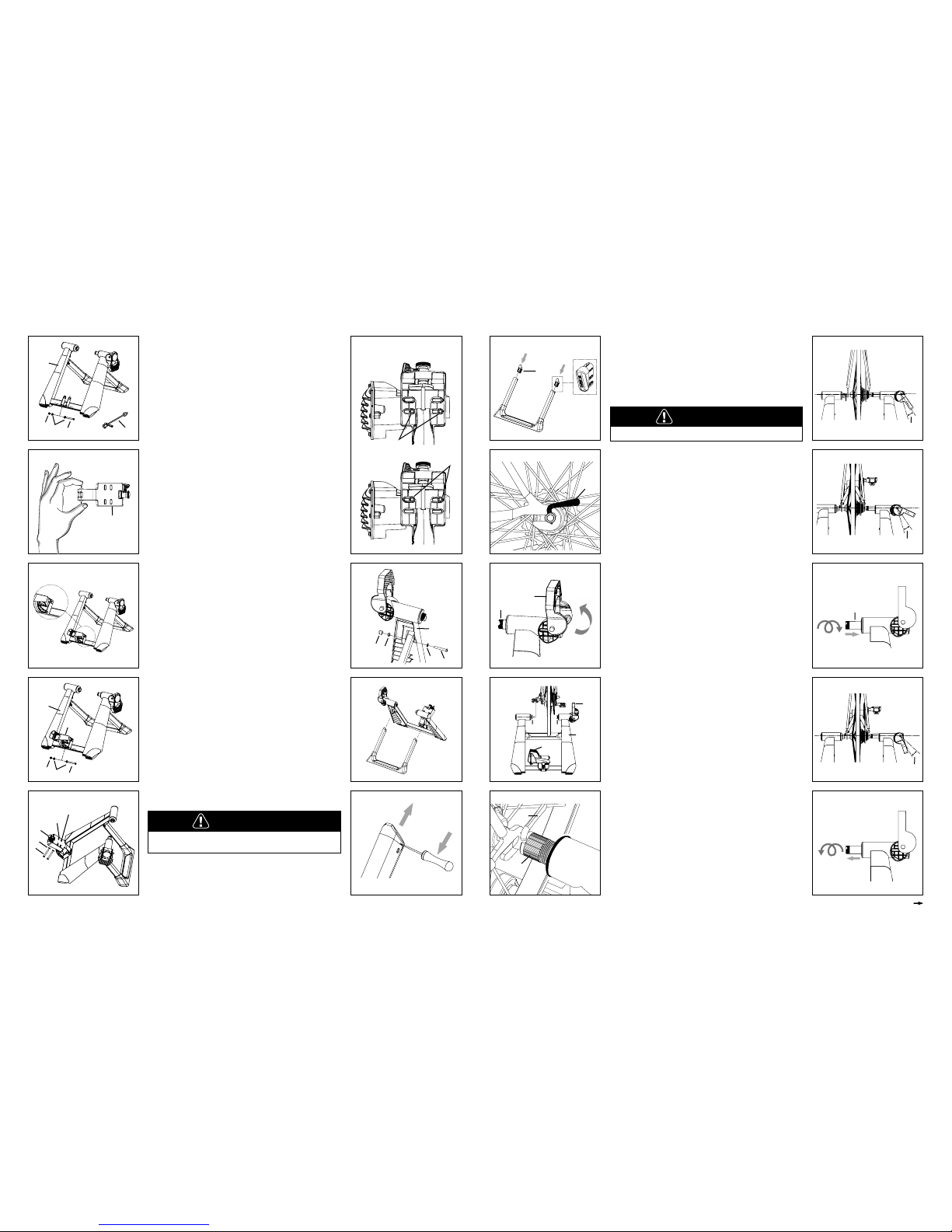
1. Remove the trainer frame, resistance unit and all parts from the
box. Open the frame and set it on a flat, stable surface.
2.
Use the included 5mm hex wrench to remove the bolt, washers
and nut (J) from the frame (A). See Figure 1.
3. Attach the base plate (C) to the frame (A). Depress the two buttons
at the end of the base plate with your fingers and align them with
the holes in the tabs on the trainer frame. See Figure 2 and 3.
Then reinstall the bolt, washer and nut (J) and tighten. See Figure 4.
4.
Use the included 5mm hex wrench to attach the resistance unit
(B) to the base plate (C) using two bolts and washers (I). See
Figure 5 and 6. There are two sets of mounting holes in the base
plate to accommodate different wheel sizes. Use the appropriate
set of mounting holes for your wheel size.
5.
For wheels with a diameter larger than 28”, you should also
replace the plastic plugs in the front legs of the trainer frame to
reduce the open angle of the frame. This requires removing the
front legs from the trainer frame.
a. Remove the nut cover, nut, bolt and washer (K) from each leg
and remove the legs from the frame. See Figure 7 and 8.
b.
Use a small flat blade screwdriver to remove the plastic end cap
(L) from the end of each leg and install the included end caps in
their place using a rubber mallet if necessary. See Figure 9 and 10.
c. Align the legs with the frame and reinstall the bolts, washers,
nuts and nut covers (K).
Page 2
BICYCLE INSTALLATION:
1. Replace the bicycle’s rear wheel quick release (QR)
skewer with the one provided (M) with the trainer. Orient the
QR skewer lever so it is horizontal and pointed toward the
rear of the bike. See Figure 11. See bicycle owner’s manual
for instructions on how to properly adjust the QR skewer.
Make sure the QR skewer is tight and not damaged or bent.
2. Set the trainer on a flat, stable surface and open the lever
handle (D). See Figure 12.
3. Lift the bicycle into position and fit the QR lever on the
left side of the wheel into the left axle support cup (G). See
Figure 13. Orient the axle support cup so the notch in the cup
is at the top and aligned with the lever. See Figure 14.
4. Close the lever handle (D), making sure that the right side
axle support cup (H) begins pressing against the QR skewer
nut within the 55 to 65 degree working range of the handle as
shown in Figure 15.
5. If the axle support cup begins pressing against the QR
skewer nut too soon (see Figure 16), open the lever handle
(D) and thread the right side axle support cup (H) further into
the frame by turning it clockwise. See Figure 17.
6. If the axle support cup does not begin pressing against the
QR skewer nut soon enough (see Figure 18), open the lever
handle (D) and thread the right side axle support cup (H)
further out of the frame by turning it counterclockwise. See
Figure 19.
7. Once the extension length of the right side axle support
cup is adjusted correctly, lift the bicycle into position again,
fitting the QR skewer lever into the left side axle support cup
(make sure the cup is still oriented with the notch at the top to
accommodate the QR skewer lever—see Figure 14).
8. Close the lever handle (D) with the palm of your hand so
that the right side axle support cup (H) presses against the
QR skewer nut, clamping the bicycle in place. Make sure the
QR skewer lever and QR skewer nut are fully seated in the
axle support cups.
9. Check that the bicycle is securely attached to the trainer
by pushing or pulling on the bicycle’s top tube or seat. If the
bicycle is not secure, check to see that the QR skewer lever
and nut are properly positioned in the axle support cups and
that the lever handle is in the fully closed position.
10. Check the position of the rear wheel on the resistance unit
roller. While it is not necessary for the rear tire to be perfectly
centered on the roller, you may encounter a clearance
issue between the tire and resistance unit if the wheel is not
centered, particularly when using wider tires. See Figure 20.
To center the wheel on the roller, loosen the resistance unit
attachment bolts (I), slide the resistance unit left or right as
necessary, and re-tighten the bolts. See Figure 21.
Failure to securely attach bicycle to trainer could
result in serious injury.
WARNING
USING YOUR TRAINER:
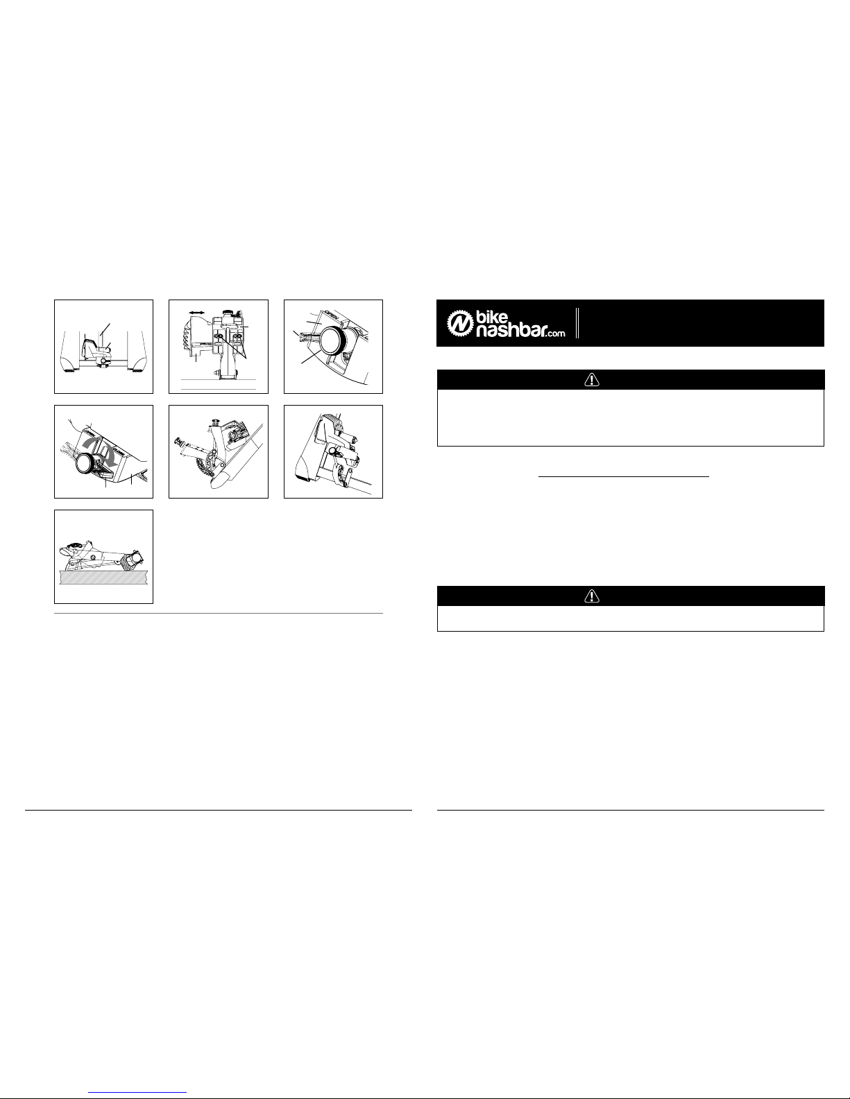
1. Make sure the red load lever (E) on the resistance unit is in
the OPEN position. See Figure 22. Then turn the resistance
unit control knob (F) counterclockwise until the resistance unit
roller contacts the tire. Once the resistance unit roller contacts
the tire, flip the load lever (E) to the CLOSE position. See
Figure 23.
Fig 6
A
M
J
J
J
Fig 1
Fig 10
C
Fig 2
OPEN CLOSE
Fig 11
Fig 3
! CLICK !
! CLICK !
Fig 12 Fig 17Fig 7
Fig 4
C
J
J
J
Fig 13Fig 8
Fig 5
C
I
I
29”
26”/650c/27”/700c
Fig 9
26”/650c/27”/700c
29”
A
K
K
K
K
L
L
M
2. Fluid resistance provides smooth, naturally progressive
resistance that varies according to your wheel speed. You can
use your bicycle’s gearing the same way you would on the
road---lower gearing will generate less resistance (suitable for
a warm-up or light recovery riding) while higher gearing will
generate more resistance and a more intense workout.
3. To make your indoor workout as quiet as possible, set the
trainer on a trainer mat and use a rear tire with a smooth
tread pattern.
4. Riding on an indoor trainer may cause your rear tire to
wear more quickly than riding on the road. To minimize tire
wear, avoid letting the tire slip against the roller. Apply power
evenly when accelerating, and pedal with a smooth stroke.
DO NOT apply the rear brake while using the trainer. Use a
smooth tread tire that is at least 23mm wide and maintain the
maximum recommended inflation pressure for your tire.
5. If the rear tire continues to slip on the roller, flip the red
load lever (E) to the OPEN position. Turn the resistance unit
control knob (F) counterclockwise to apply additional pressure
to the rear tire and then flip the load lever to the CLOSE
position.
BICYCLE REMOVAL:
1. Flip the red load lever (E) on the resistance unit to the
OPEN position.
2. While supporting the bicycle, open the lever handle (D) and
lift the rear wheel up and forward to remove the rear axle from
the axle support cups.
3. The QR skewer provided with the trainer can be used
when riding the bicycle off the trainer as well. If you choose
to reinstall your bicycle’s original skewer, refer to your bicycle
owner’s manual for instructions on properly adjusting the
skewer. Before riding, ensure the quick release skewer is tight.
TRAVEL AND STORAGE:
1. To fold the trainer for transport or storage, raise the
resistance unit to the vertical position by turning the control
knob (F) counterclockwise as far as it will go. See Figure 24.
2. Fold the upright frame legs together. You can further
reduce space by releasing the resistance unit from the frame
and folding it flat. See Figure 25 and 26.
D
I
I
H
D
A
B
G H
Fig 19
H
figures continued on next page
Make sure resistance unit cable is clear of all moving parts.
CAUTION
M
G
Fig 14
A
Fig 15
Fig 16
Fig 18
55ₒ 65
ₒ
55ₒ 65
ₒ
55ₒ 65
ₒ
 Loading...