

Page 1
N1178
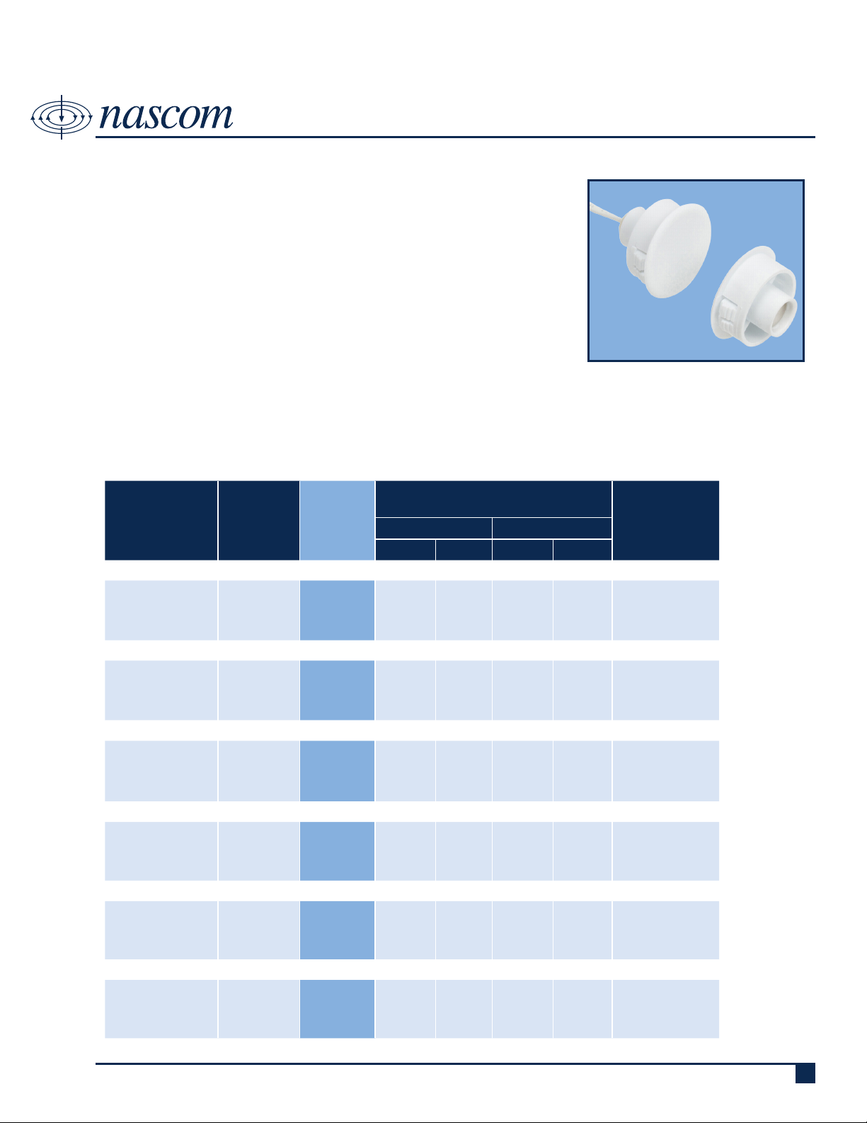
1” RECESSED WIDE GAP STUBBY DOOR CONTACT SET
DESCRIPTION
Nascom’s N1178 Series is a 1” recessed wide gap stubby door contact designed for residential, commercial and industrial steel and wood door applications.
The N1178 is the installer’s choice of contact conguration because the contact set is designed to cut installation times and helps to prevent false alarms
caused by shifting or warping doors.
The N1178 Series is designed for installation in every type of hinged door
including wood doors.
FEATURES
• SNAP FIT ON STEEL - NO GLUE REQUIRED • ENCAPSULATED HERMETICALLY SEALED CONTACTS
• 12” 22AWG WIRE LEADS • POLYPROPYLENE HOUSINGS
• WIDE GAP - N35 NdFeB RARE EARTH MAGNET • LISTED TO UL634 STANDARD
ORDERING INFORMATION
CONTACT RATING
PART
NUMBER
COLOR
OPERATE
GAP
(in inches)
(Max DC/Peak AC Resistive)
SWITCHING CARRY
V I V I
CLOSED LOOP, NORMALLY OPEN, 1FA, SWITCH/MAGNET SET:
N1178B/ST
N1178G/ST
N1178T/ST
N1178W/ST
BROWN
GREY
TAN
WHITE
0.875 to 1.50 200 VDC 0.5 Amps 10vA 1.5 Amps 150 mOhms
DUAL CLOSED LOOP, NORMALLY OPEN, 1FA, SWITCH/MAGNET SET:
N1178B/ST2CR
N1178G/ST2CR
N1178T/ST2CR
N1178W/ST2CR
BROWN
GREY
TAN
WHITE
0.875 to 1.50 200 VDC 0.5 Amps 10vA 1.5 Amps 150 mOhms
OPEN LOOP, NORMALLY CLOSED, 1FB, SWITCH/MAGNET SET:
N1178B/STFB
N1178G/STFB
N1178T/STFB
N1178W/STFB
BROWN
GREY
TAN
WHITE
0.75 to 1.25 30 VDC 0.2 Amps 3vA 0.5 Amps 150 mOhms
SINGLE POLE DOUBLE THROW, SWITCH/MAGNET SET:
N1178B/STSD
N1178G/STSD
N1178T/STSD
N1178W/STSD
BROWN
GREY
TAN
WHITE
0.75 to 1.25 30 VDC 0.2 Amps 3vA 0.5 Amps 150 mOhms
DOUBLE POLE DOUBLE THROW, SWITCH/MAGNET SET:
N1178B/STDD
N1178G/STDD
N1178T/STDD
N1178W/STDD
BROWN
GREY
TAN
WHITE
0.75 to 1.25 30 VDC 0.2 Amps 3vA 0.5 Amps 150 mOhms
HIGH SECURITY, NORMALLY OPEN, 1FA, SWITCH/MAGNET SET:
N1178B/STHS
N1178G/STHS
N1178T/STHS
N1178W/STHS
BROWN
GREY
TAN
WHITE
0.1875 to
0.5000
300 VDC
0.25
Amps
10vA
Royne Industries LLC, dba NASCOM
|
P: 800.843.5530
|
F: 800.727.4041
0.25
Amps
STATIC
CONTACT
RESISTANCE
(50mV, 100mA)
150 mOhms
initial
|
www.nascominc.com
DWG No. 120605-01 Rev. 1
1
Page 2
9.53
.375
20.32
.800
12.45
.490
29.46
1.160
24.38
.960
TOP
VIEW
SIDE
VIEW
12.45
.490
29.46
1.160
24.38
.960
9.53
17.15
.675
TOP
VIEW
SIDE
VIEW
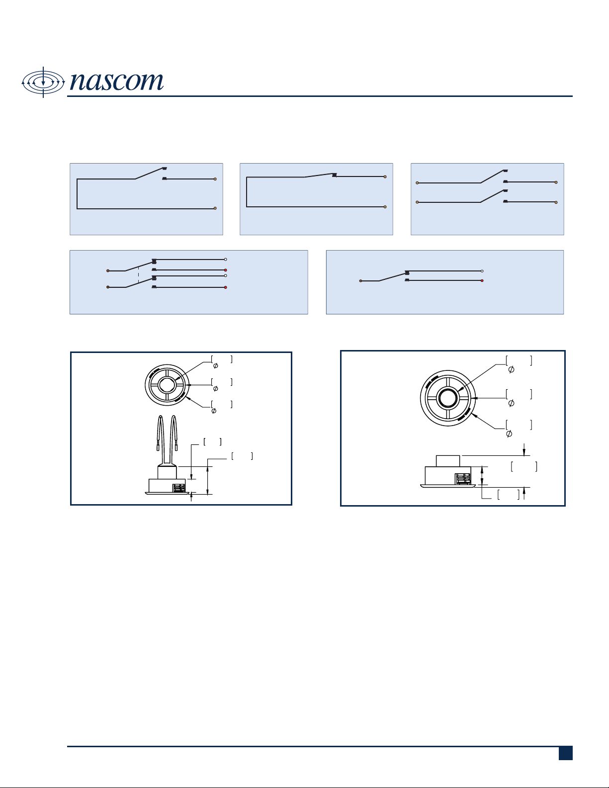
WIRING SCHEMATIC
N1178
1” RECESSED WIDE GAP STUBBY DOOR CONTACT SET
SWITCH
CONTACT
CLOSED LOOP,
NORMALLY OPEN CONTACT
COMMON
(BROWN)
COMMON
(BROWN)
OPEN LOOP,
NORMALLY CLOSED CONTACT
NC, OPEN LOOP (WHITE)
NO, CLOSED LOOP (RED)
NC, OPEN LOOP (WHITE)
NC, OPEN LOOP (RED)
SWITCH
CONTACT
COMMON
(BROWN)
DUAL CLOSED LOOP,
NORMALLY OPEN CONTACTS
DPDT, DOUBLE POLE DOUBLE THROW SPDT, SINGLE POLE DOUBLE THROW
DIMENSIONS - IN [mm]
NC, OPEN LOOP (WHITE)
NO, CLOSED LOOP (RED)
SWITCH
MAGNET
INSTALLATION INSTRUCTIONS
• Mark location for the switch on the door frame and mark the location for the magnet on the door.
• Make sure switch and magnet hole locations are aligned.
• Drill holes for the switch and magnet using a 1” Hole Saw for steel doors or a Forstner bit for wood doors.
• Press the magnet into the hole in the door until seated rmly against the head. Silicone may be used to secure the
magnet in wood doors.
• Connect the switch leads to the alarm circuit conductors. Hold the wire leads (not the switch housing) when cutting and
stripping to prevent damage to the switch.
• Feed the switch conductors into the hole and insert the switch housing pressing rmly until seated. Silicone may be used
to secure the switch in wood doors.
• Test switch for correct operation and make sure gap performance is acceptable.
Royne Industries LLC, dba NASCOM
|
P: 800.843.5530
|
F: 800.727.4041
|
www.nascominc.com
DWG No. 120605-01 Rev. 1
2
Page 3

PART NUMBER SYSTEM
N1178
X XX XXX/ XXXX XX XXX X
N1178
1” RECESSED WIDE GAP STUBBY DOOR CONTACT SET
XX
COLOR:
• B = BROWN
• G = GREY
• T = TAN
• W = WHITE
PRODUCT TYPE (1 or 2 digits):
• ST = SWITCH/MAGNET SET
• SW = SWITCH ONLY
• M = MAGNET ONLY
CIRCUIT (0, 2 or 3 digits):
• Blank = CLOSED LOOP
• 2CR = DUAL CLOSED LOOP
• FB = OPEN LOOP
• SD = SPDT
• DD = DPDT
• HS = HIGH SECURITY
LEAD LENGTH (zero, 3 or 4 digits):
• Blank - 12 Inches
• All other lengths specied in
Inches with 3 digits (e.g. 036 =
36 Inches)
END OF LINE RESISTOR (zero to 4 digits):
• Blank = Resistor in series with the switch
• P = Resistor in parallel with the switch
• SP = Resistor 1 in series to the switch; resistor
2 in parallel to the switch
BUILT-IN END OF LINE RESISTOR VALUE (zero to 4
digits):
• Blank = No built-in end of line resistor
• All other resistor values are specied (e.g. 1K
= 1,000 Ω)
LEAD WIRE COLOR (zero to 2 digits):
• Blank = Switch Color except:
» resistor contacts standard is red wire
» all 2 conductor jacketed wire is grey
• BL = Blue leads
• OL = Orange leads
WIRE TYPE (0 or 1 digit):
• Blank = UL1061 | 22AWG | 7/30
• Z = Zipcord ZIP NEC (UL) TYPE CL2
• J = 2-conductor PVC Jacketed NEC Type CL2
and CM
Royne Industries LLC, dba NASCOM
|
P: 800.843.5530
|
F: 800.727.4041
|
www.nascominc.com
DWG No. 120605-01 Rev. 1
3
 Loading...