

Nascom N1175123787W-STFB, N1175123787W-ST2CR, N1175123787W-ST, N1175123787T-STFB, N1175123787T-ST2CR Specsheet
...Page 1
N1175 123787
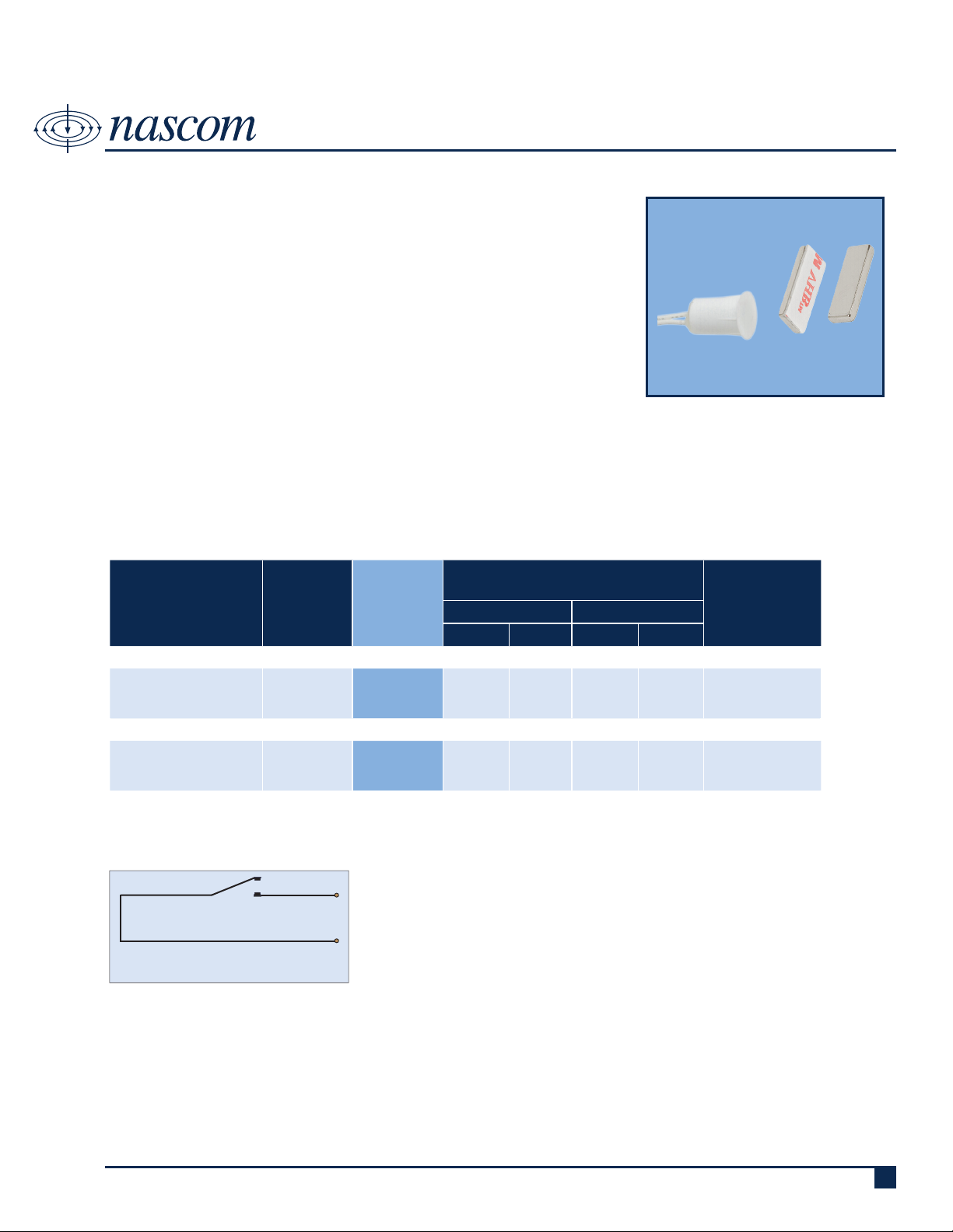
3/8” RECESSED MINI CONTACT WITH NdFeB BAR MAGNET
DESCRIPTION
Nascom’s N1175 123787 Series, mini 3/8” recessed contact with NdFeB bar
magnet, protects all nonferrous (e.g. wood, aluminum and vinyl) doors and
windows, in both residential and commercial settings.
The N1175 123787 is the installer’s choice of contact conguration where drill
depth is critical and excellent air and side-to-side gap are required to prevent
false alarms caused by shifting or warping doors and windows due.
FEATURES
• PRESS FIT SWITCH- NO GLUE REQUIRED • ENCAPSULATED HERMETICALLY SEALED CONTACTS
• 12” 22AWG WIRE LEADS • POLYPROPYLENE SWITCH HOUSING
• WIDE GAP - N35 NdFeB RARE EARTH MAGNET • LISTED TO UL634 STANDARD
ORDERING INFORMATION
CONTACT RATING
PART
NUMBER
COLOR
OPERATE
GAP
(in inches)
(Max DC/Peak AC Resistive)
SWITCHING CARRY
V I V I
CLOSED LOOP, NORMALLY OPEN, 1FA, SWITCH/MAGNET SET:
N1175123787B/ST
N1175123787G/ST
N1175123787W/ST
HIGH SECURITY, NORMALLY OPEN, 1FA, SWITCH/MAGNET SET:
N1175123787B/STHS
N1175123787G/STHS
N1175123787W/STHS
BROWN
GREY
WHIITE
BROWN
GREY
WHIITE
0.50 to 0.750 200 VDC 0.5 Amps 10vA 1.5 Amps 150 mOhms
0.1875 to 0.50 300 VDC
0.20
Amps
3vA 0.5 Amps
STATIC
CONTACT
RESISTANCE
(50mV, 100mA)
150 mOhms
initial
WIRING SCHEMATIC - IN [mm]
SWITCH
CONTACT
CLOSED LOOP,
NORMALLY OPEN CONTACT
Royne Industries LLC, dba NASCOM
|
P: 800.843.5530
|
F: 800.727.4041
|
www.nascominc.com
DWG No. 131119-03 Rev. 1
1
Page 2
.680
17.27
.030
0.76
.465
11.81
.355
9.02
FRONT
VIEW
TOP
VIEW
.875
22.23
.125
3.18
.375
9.53
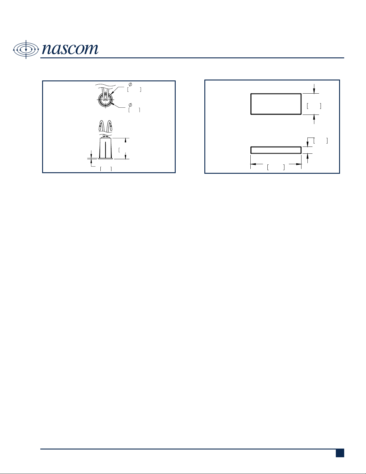
TOP VIEW
FRONT VIEW
DIMENSIONS - IN [mm]
N1175 123787
3/8” RECESSED MINI CONTACT WITH NdFeB BAR MAGNET
SWITCH
MAGNET
INSTALLATION INSTRUCTIONS
• Mark location for the switch on the door frame and mark the location for the magnet on the top edge of the door.
• Using a square, transfer the marks on to the top edge of the door and the opposing door frame.
• Using a tape measure or graduations on the square, locate the center of the door edge and place an intersecting line with
the rst mark. Remove the release liner for the VHB tape on the back of the magnet and position the end of the magnet
at the intersecting line.
• Repeat the above step to locate the hole position for the switch in the door frame. Drill a 3/8” hole in the door frame.
• Align the end fo the magnet to the switch body.
• Connect the switch leads to the alarm system. Caution! Hold wire leads, not the switch housing while cutting and
stripping to prevent damage to switch.
• Insert wire leads into hole followed by the switch and press the switch into the hole until the head is ush with the door
frame
• Test switch for correct operation and make sure gap performance is acceptable.
Royne Industries LLC, dba NASCOM
|
P: 800.843.5530
|
F: 800.727.4041
|
www.nascominc.com
DWG No. 131119-03 Rev. 1
2
Page 3

PART NUMBERING SYSTEM
N1175 123787
3/8” RECESSED MINI CONTACT WITH NdFeB BAR MAGNET
COLOR:
• W = WHITE
• B = BROWN
• G = GREY
CIRCUIT (0 or 2 digits):
• Blank = CLOSED LOOP
• HS = HIGH SECURITY
BUILT-IN END OF LINE RESISTOR VALUE
(zero to 4 digits):
• Blank = No built-in end of line
resistor
• All other resistor values are
specied (e.g. 1K = 1,000 Ω)
N1175123787
END OF LINE RESISTOR (zero to 4 digits):
• Blank = Resistor in series with the switch
• P = Resistor in parallel with the switch
• SP = Resistor 1 in series to the switch; resistor
2 in parallel to the switch
X ST XX/ XXXX XX XXX X
XX
LEAD WIRE COLOR (zero to 2 digits):
• Blank = Switch Color except:
» resistor contacts standard is red wire
WIRE TYPE (0 or 1 digit):
• Blank = UL1061 | 22AWG | 7/30
• Z = Zipcord ZIP NEC (UL) TYPE CL2
LEAD LENGTH (zero, 3 or 4 digits):
• Blank - 12 Inches
• All other lengths specied in Inches with 3
digits (e.g. 036 = 36 Inches)
Royne Industries LLC, dba NASCOM
|
P: 800.843.5530
|
F: 800.727.4041
|
www.nascominc.com
DWG No. 131119-03 Rev. 1
3
 Loading...