

NASA Saturn S-1 Stage, Saturn SA-1 Handling, Transporting And Erection Instructions
HANDLING,
TRANSPORTING
AND
ERECTION
SATURN
INSTRUCTIONS
S-l
STAGE,
SA-1
,
J
:
....
GEORGE
."
C.
MARSHALL
SPACE
HTTP://HEROICRELICS.ORG
HUNTSVILLE
FLIGHT
ALABAMA
CENTER
TITLE
Handling, T
Erect
ion
ranspor ing,
Inst
ructions, Sat urn S
Stage
~
SA
=1
And
T
ABLE
=1
OF CONTENTS
GEORGE
MARSHALL
SPACE FLIGHT
PROCEDURE
DATE
PAGE
1
1
OF
c.
CENTER
147
Paragraph
LIST
INTRODUCTION
10
OF
CHAPTER
PREPARING
ILLUSTRATIONS
0
000
000
Q
I T
RANSPORTATION,
BOOSTER
VOOOGOOOOOOOOOOOOOOOO
<:)
I,)
U 0 0
(J
0
HANDL
FOR
ERECTION
000000
0 0 0 0 0 0
ING,
AND
ooooooooo
101 Positioning Transporter (J=AF= 2004)
102
"103
2 0 ER
2
2~2
30
Installing
and
Removal
ECTI.NG
01
Posit~oning
Removing
T
hrus t Ring
REMOVING
Bumper
Two
Cable Asse mblies (J=1
Procedu
BOOSTER
Transpor t
Booster
BOOSTER
Assembly (D=
re
Rear Ring Sec
0 I,)
(J
0 0 0 v 0 0 0 0 0 0 0
er
from T
0,)
a 0 0 0
()
0 0 0 0 0 0 a 0
FROM
TEST TOWER
10426438) ,
0424771)
'ti
(.0
(J 0 (J
and At
tachin
ransporter
()
U 0 0 0 0 a 0 0 0 0
ons (J=AF91200
0 0 u 0 0 0 0 0 0 0 0 0 0 0 0 0 0 0 0 0 0 • a 0 0 0 0 • 0 0 Q
and Pos
Ovooooouooooooooooooooo
O .
OOOCOOOOOQO
I)
0 0
00000.)
0 0 0 0 0
ERECTION
o
oooooooooooooooouoooooooooooo
AT STATIC TES
oooooooooooooo
Two
Bumpers
oo oo
ooo
g Erection
itioni
(J
C.
0 0 0 0 0 v 0 0 0 0 0 GOO. 0 a 0 0 0 0 0 0 0
Page
OOO
OOOOOOOOOOOO
(.I
0 0
000
000000
o
ooopoooooooooo
(D=
. o o
oouoooooooooo
4=2
=0 000000000000000
0000
T T
OWER
10426434) ,
.
0 0
ooooo
(I
OO
O
000
000
o'o
I)
C 0 20
11
Cables 000000000000000 20
ng
on
Tower
(I
0 0 0 28
o
ooooooooooouo
35
3
5
7
7
7
7
3
01
Prepar
302
Removing
Trans
303
304
Installation
Removing
and
CHAPTER
10
PREPARING
1
01
Preparing
102
103
Positioning
Insta
(J
ing
Booster for
Booster from Towe
porter
Bumper
Two Cable
II
TRANSPORTATION,
BOOSTER
Servi ce St ruct
Tran
lli
ng
Beam
""",
1 0426668) 0 0
Removal
ooooovooo"oooo
r Thrus t Ring and
0 0 0
0.)
0 0 0 0 0 0 0 0 0 0 0 0 0 0 0 0 0 0 0 0 0 a 0 0 0 0 " 0
Proced
ure
Assem
Rear Ring Sect
bly
(D=1
0426438) , Two
Assemblies (J=10424771)
HANDLING9 AND
FOR
ERE
CTIO
N 00000000000000000000000000
ure for Er
sporter
Weldmen
()
0 0 0 0 0 u 0 v 0 0 0 0 0 Q 0 0 0 0 0
(J=AF= 2004 0000000000000000000 .
t (J=10426675) and Forward
ion
ERECTION
ecti
on
coo
o
ooo
ooooo
Pos
itioni
\.'I
0 0 0 0 0 0 0 0 0 0 0 0 0 0
s (J=AF=1
2004=2=0) 000
Bumpers
0000000000
AT
CAPE
ooocooOoooooooooooooo,ooo
0 0 0
I)
0 0 0 0 0 0 0
ooooooooooooo
ng
on
(J
0 0 0 0
ooo
0;1
0000000
(D=
10426434)
00 00
000.' 0 0000000000
CANAVERAL
00000
00000
00000000
oooo
000000000000
Sling
Assemblies
I;)
0 0 0 0 0 0 0 0 0 0 0 0 0 0 0 0 0 51
35
0 0 37
40
44
47
47
47
47
EORGE C.
PROCEDURE
MARSHALL
EP=141
SPACE
PAGE
FLIGHT
CENTER
OF
2 1
47
TABLE
OF
CONTEN
TS
(Con
o)
Paragraph Page
104
105 Removal
:2
2
,2
30
40
4
4~2
Remova
0
EREC
TING
01
Posit
2
Removing
0
REMOVING
REMOVING
RING DET
.1
Removing
front Trans porter
Preservi
l Procedure Forward Ri
Procedure Rear Ring Secti
BOO STER
ioning
Booster
BOOSTER
RING
AILS
Forwa
ng
Forward and Rear Ring Deta
I)
0 0 0 0 0 0 0 0 0 0 0 0 8 0 0 0
Transport er and A
from Transpor t
FROM
LAUNCH
SECTIONS
AND ATT
WITH
ACHING
rd and Rear Ring Sect i ons w
I)
0 0
(.)
0 0 0 0 0 0 0 0 0 0 0 0
ng
Sectio
tta
er
PEDESTAL
ns (J=AF=12
ons (J=AF=1
(I
Q 0 0 0 0 0 0 0 0 0 0 0 0 G
ching Cab
and
Pos
les
iti
00000000000000000000000
2004=2=O)
0000000000000000000000000 64
oning on Launch
FIN I IDENTIFICATION
HARDWARE
0000000000000000000000
ith
Fin
4)
0 0 0
00
0 0 0 0 0 0 u 0 0 0 0 • 0 0 0 0 0 0 0 0
i!L
s and Attachi
004
=3=O)
000000
0000000
0000000000000000
OO
0 0 0 0 0 0 Q 0 0 0 0 0 " 0 0 0 e 0 0 0
Pedestal 0 72
00000000
AND
PRESERVING
ALL
0.000000000
I Ident
ification
ng
Hardware a 0
I)
I.) 0 0 0 0 0 0 0
54
60
64
0.
79
80
8D
eo
0 0
82
CHAPTER III
GENERAL
INSTRUCTIO
NS
FOR THE
8=1
T
RANSPORTER 0000
0000
000
0000
00
83
LIST
OF
ILLUSTRATIONS
PAGE
OF
EP-141 3 147
Figure
1.
2"
3.
40
Positioning
Removing Doors and
Installing Bumpers
Positioning
Equipment at
Horizontal
5. Removal of Rear Ring Sec
6.
7.
8.
9Q Erect
100
11
• Connect
2.
1
Rear Ring Sect
Removal
of
Identification
ion
Attaching
ion Attaching
Rear Ri
of
Beam
Ins t
Erection
ng
Fin
allation
ing Aft Cable Assembly
Forward Support Clamps
Static
Plates
oooe
and Cable
Pla
tform and
ti
ons
Section
Line
and Out
Beam
and Cable Assemblies 0' 0000'
o.
0 0 • 0 0 • 0 • 0 0 0 0
Title
Test
Tower 0000
o o o
oooo
o
ooocooooooo
Assemblies
0.000 •• 0
Personnel
(J=AF=12004-2~0
Poin
ts
•••
000. 0. 0.00.0 •• 0,'0
at Outrigger
rigger
oeeoooooooooo
••• 00. o
Noo 2
Numbers
ooooo •••
••
0 ••• 0 0 0 0 • 0 0 • 0 0 • 0
•.•
0 0 0 • 0
•• 00. 0 •• 0
o
CJOOOOOClOOOO
••• 0 ••••
•••
• 0 •.
O O O O 9
00
•. 000.0 10
000000.00"00'.00..
)
0.0
00000.00 •••••
.'0
•• 0" 0 14
••• 0 .. 0 .....
0'0.0.00.00
oo
• • o
ooooo
00.0.
•• 0
ooeoo
0000000'0 0" 0 23
.•
0 . 0 0,' • 0 0 0 .' 0
••• 0 00
. 0 • • 25
•••
0 • • •
00
0.
..
oo
Page
8
12
13
18
19
21
27
13 0
14. Boost
15.
16
0
17.
18.
19.
20.
21.
22.
23
. Forward Ring Section Removal
24 .
Lifting
Boost
Positioning Boost
Preparing
Boost
er
Stabilization
er
in
er
Vert
Serv
ice Structure
off
Transporter
ical
Position
er
on
Preparatory
Positioning Equipment at
Preparing
Installa
ti
Boost
on
of
er
Beam
for
Erection 0 0 •• • •• 0 • •• 0
Weldmen
Removing Forward Ring Sect
Forward Ring
Attaching Aft
Section Attaching
and Forward
0 •• 0 • •
0000000
t o
Lifting
••••
000
..• 0 .•.•
0. 0 •• •• •• 0. 0. 0.0 0.· •
Support Bracket s 0.00 . 0
for
Erection
Firing Sit e 0
.000.00 •••
•••. 000. 0
•.
t and Forward
ions
(J=AF-12004~3~0) .~
Poin
t s
Procedures
Sling
Assemblies .000
•••
Sling
0 .
.0 .0
.... 00. 0 ••
••••
00
•• 0. 0000.000 •• 29
off
Transporter
0000
000
00
••
0. 0
•.••••..
. 0
••••••.
••• •• 0......
• . 0. 31
•••
•• 0 33
0 •• 36
0. 0
..
0 0 0 0 0 • 0 • 0 ••• p 0 0 0 0 . . •
Assemblies
0.
00
•••
00
00
••••
• 0.
•••• 00
.. 0 ••••• 00..
00
••
0' o . 00" 0
......
00
. • 00. 0
0 •• 0 56
00
48
49
52
53
55
57
65
GEORGE
C.
PROCEDURE
MARSHALL SPACE FLIGHT CENTER
EP
,·,1
41
PAGE
4
OF
147
Figure
Connec
26
27
28
0
.
.
L
8-1
Removing
29. Booster-
30.
31 0 Rear Ri ng Support Cl
P
ti
ng
ifti
ng Boost
Stage
Af t Cable Assembly and
Pedestal
to-
ositioning
Erect
ing
er
off
Cen'ter-or-Gravi
0
III
0 .
000
Launch
Boost
LIST OF
Beam
Transpor
••
0.0
ILLUSTRATIONS
Ti t
le
and Forward
er
0
•• 0 ••••
ty Di agram
Positioni
Q 0 • • " 0 • • 0 e • • 0 II 0 . 0 0 0 .
(Con
Sling Assemblies
• 0 • • 0
••••••
ng
o)
• 0 • • 0 • •
Booster
....
Pedestal Orientation Diagram..
er
on
Support A
amp
s Q. 0 0 • 0 0 • ·0 u •
rms
and Holddown
••
0
••
0 •
III
0 • 0
••
0 •
•••••
••••
...
0 0
. ..........
Arms
•••
••••
0 •
•• ••
on
!oJ
00000
.0...
•
•
•• 0..
•••••
00.
• 0 • •
Launch
•••
" 0 0
••
...
....
III
•••
0 • • • • • • 81
Page
• • • 69
••
• • 71
00
. 75
..
..
68
77
78
ER
Thi s
manual provide
erecting
and
chapt
II
ta
ers 0 Chapter
con
tai
ns
i ns
opera
ins
t i ng
Chapter I consi st s
sections,
va
tion
of
t he
Chapter
rear
pedes t
position
of tooling
rear ring sect i ons t o t he
II
ring
sections, posi t i oning and
al,
and
A complet e
T
ransporter
and Int
roducti
Equipmen
t ower and
por
t e
r, towing tractor
ranspor
t
handling
and i ncluding a
t e
at t he Cape Canaveral f
tat i on ring pl a t forms .
of
t he Boost er d
s t he necessary in
t he Saturn S
=I
Booste r
I cont ai ns instructi
t ruct i ons at t he
ins
t ructions
of
st ep=by=st ep procedures
i ng and erecting the
, pos
iti
oning
cons i st s
preserva
man
ual
of
t i on
con
taini
st ep=by=st ep
of tool
on i s inserted i n
ssential
t o proper ha
, gant
urin
INTRODU
~
ef
Cape Canaveral
for
t he Sat
t he Boost
Booster aft
erecting 'the Boost
i ng
ng ge
separa
neral inst
t e Tab l e
thi
s manual
ndling of
irin
g site i
ry
cra
ne, mobil
Sp
eci
al
g r e
mov
al
CTI
ON
st r uct i ons
fectivity SA
ons at t he
f i ri
urn
S=I T
ransporter
Boost
er
on t he t
er
i n t he
er sta
procedures
for shipp ing.
ructions
of
Con
t ent s ,
as
Chap
t he Boost
nclu
des t he fol
e c
rane, fork
hardware
and
erection.
assures
for transporting,
=1
and
is divided int o t
static tes
ng sit e.
t tower.
Chapter
.
for
r e
moving
t he
static test t ower ,
ransp
or t
er,
and
t i c test
for
for
firing
removi ng t he
er
from t he
t he Sat
List of
t er
III
.
er
at t he
lowing: trans
l i f t ,
safe
horizontal
and
handling
Chapter
III
rear ring
reassembly
.
forward
launch
urn
S=I
Ill
ustrati
static tes
efficient
hree
con=
pres
and
ons,
t
=
and
,
er -
Divi
T
his
sions
publ
0
i cat i
on
i s a
com
bin
ed
effort
of
t he M=
LOD, M=T
EST,
and M-
F&AE

PROCEDURE
PAGE
OF

CHAPTER
I
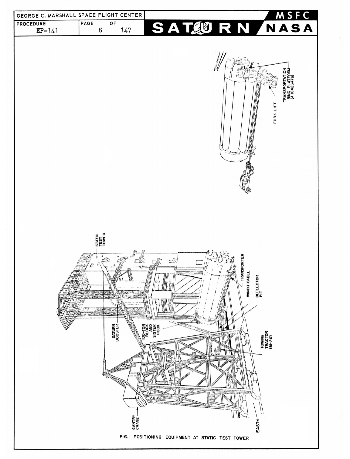
1.
PREPARING
1.1
1
Pos
1.1.
1.
.2
Installing
and
1.
1.2.2
TRANSPORTATION,
BOOSTER
iti
oning
1 Pos
r i ght
FOR
Transporter
iti
on transporter
angle
bridging
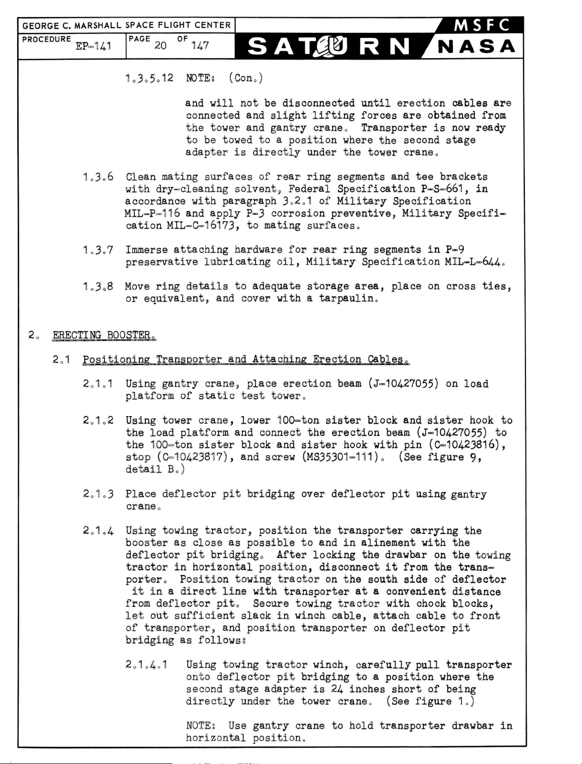
1.2
area
Lock t
around
(See
figure 1 for
ransporter
Bumper
Two
Cable Assemblies
2.1
Move tractor
boos t
Using
er
fork
personnel
(D-10426438) , t
(J-10424771) . (See
HANDLING,
TEST T
ERECTION
0
(J=AF=12004
on nort h
t o
deflector pit
at a di stance which
t he t
ransporter
the rel ative
brakes
and chock wheels .
Assembly (D-10426438).
(J-10424771~
and t
ow
bar
.
lift,
raise transpor
to a height necessary
wo
bumpers (D-10426434
figure 2.)
AND
OWER
)o
for
clear
ERECTION
side
of
and
aline
will
provi de
t he mobile
positions
Two
of the
tat
ion
for att
AT
STATIC
sta
tic tes
wit h
sufficien
of
Bumpers
forward
ring
aching
),
and
t t ower at a
deflector pit
t working
crane
and
fork
t he equipment. )
(D-1042643~
end
of
t he
pla
t form and
bumper assembly
cable
assemblies
)
lift
!
.
1.
2.1 .1
1.
2. 1. 2
1.201
.3
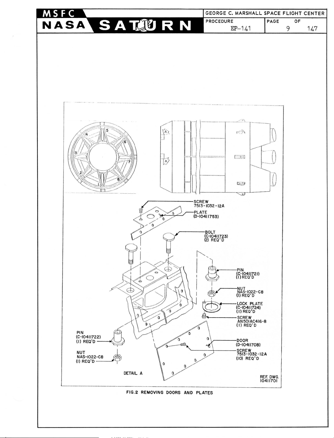
1.201.4
Remove
attached
adapter
doors
t o int
~o
gain
assembly attac
I=beams
Remove att
fairing
for
shown
NOTE:
and st
boost
No.3,
aching
t o second stage adapt
bumper
in
All
figure
assemblies
doors
oredo Th
er
has been
figure 2 for
Install
bump
wi t h detai l
Install
B
~
bumpers (D-10426434)
figure
3.
(D-10411708) and pl at
er
st age
access
hing
4,
fairing
t o bumper and
poi
nt s . Attaching
5,
6,
and 7.
hardware t hat
er
es
and second st
secures int
at at
and forward sli ng
2.
and a
i s hardwar e wi
erec
list of attaching
tta
t ed
ching
in
hardware t o be packaged
ll
be
t he test t ower. See
hardware.
er assembly (D-10426438)
A,
figure
3.
in
accordance
(D-10411753)
age
forward
poin
t s
ers
sling
are
tage
taching poi nt s
assemblies
installed aft
in
accordance
wi
t h
at
as
er the
detail
PROCEDURE
EP
=141
PAGE
OF
8 1
47
FIG.I POSITIONING EQUIPMENT
AT
STATIC
TEST
TOWER
-----
--,--
--
---------------
---
---_._-._----------
...
_-----
[I
--
L
---------
-------
--------
"~?,-.-
1%2'\
----
E§
--
---
7\
-
__
U
PIN
(C-10411722)
(I)
NUT J_
NAS-1022
(I)
~
REQ'O
~
REQ'O I
U
D
~------SCREW
/ 7513-1032 -12A
i
~
~
S>
~
I /
I)
I)
~
I
l1
i ' 1
Q '
~
I I
.r-PLATE
~
(0-10411753)
(~~~~1I723)
~
REQ'O
'1
~
I I
~
I
I)
'-----~-----SCREW
r-~~J-1022-C8
~
,
~
,,1,
.....
~
I-----SCREW
~---OOOR
{f)-~OE4J!621l
(I)
REQ'O
LOCK
PLATE
(C-10411724)
(Il
REQ'O
AN501AC416-8
(I)
REQ
' O
(0-10411708)
7513
-1032-12A
(10)
REQ' 0
-0
DETAIL
A
FIG.2 REMOVING
DOORS
AND PLATES
REF.
OWG
10411701
.
GEORGE
PROCEDURE
C.
EP=141
MARSHALL
SPACE
PAGE
10 147
FLIGHT
OF
CENTER
ill
R
BUMPER
UNSCREW
SEATED
BRACKET.
AGAINST
[~
.
~-jJ~ ,-~:~ =-i-~.:-
~~
IS
BOTH
SECURED
BOLTS
BOLT
BUMPER
BY
BOLT
AN12-14,
(AN8-6A)UNTIL
HOLDING
(D~0426438)(REF)
EACH
SHROUD
IS
TO
_-~-=~1r'
---Q--
~
"
BOLT
AN8-6A
TANI2-14
WASHER
NOTE:
WHENEVER
BOLTS,WASHER,AND
TO
BE
DISCARDED
NOTE: WIPE OFF
CLEAN RAGS
WITH
ASSEMBLIES
TOROUE
LUBRICATE
BEFORE
2-
22-WASHER NASI43-16C,RFF.
2-
HEAD
INSTALLATION
CABLE
ASSY
BOLT
NAS156-68,
WASHER
NAS~3-I.'R?
CABLE
.
ALL
OF
BOLT
THREADS,
(J-1042477il,
NUTS
SHANK
REF
AT
(NAS
fi
ASSEMBLY
SHALL
LUBRICANT FROM BOOSTER PARTS
TIME
156-68)
OF
WITH
R
_
~
1042477
BY
INSTALLED,USED
OF
REMOVAL
TO
BOLT,
AND
MOLYKOTE
_
6000
EACH
TYPE
INSTALL
PULL
IS
ATTACHED,NEW
HARDWARE
OF
SLING
INC
LBS(500FT
SIDE
OF
"G'.'
LUG
OF
IN
CABLE-
WASHERS
LINE
. LBS.).
OF
SEE
A-A
BOLT
AN14-14
WASHER
FIG
AN945-14
. 3 .
INSTALLING
2-NUT(A-10424915),
BUMPERS
AND
~
~
R
~
CABLE
ASSEMBLIES
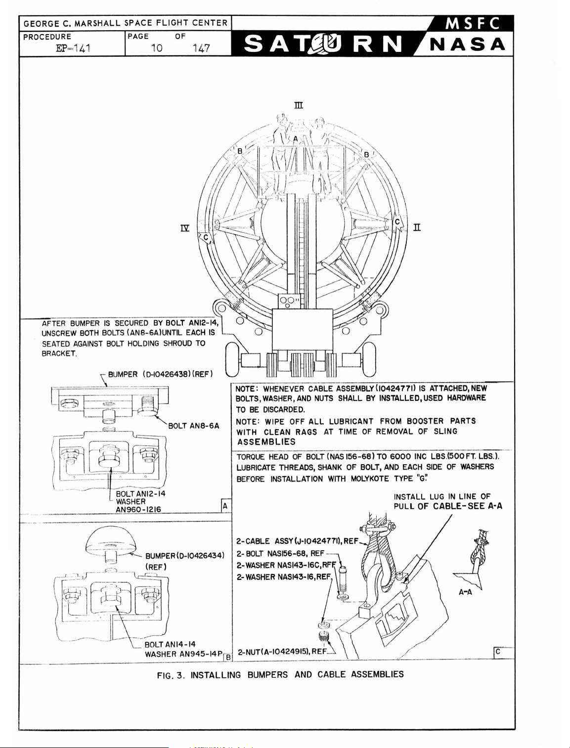
1020105 Install
w
ith instructI
assemblie
cab l e
s toget
assemblie
s (J=10424771)
ons i n deta
her
t o prevent damage to boos
il
C~
f i g
ure
in acc
30 T
ordan
ie
tero
cabl
ce
e
1
1.
03
302
2
1
0
0
01
Posi t i on m
abov e t he r e
mov
r e
Using m
and p
ring so t hat
for
ti
ono (See f i
comple
WARNIN
(J=,10424771) i s ext,remel
washers
shank and
si de
Gg
Cor
~
and nut s sha
thr
of t he
rect
eads
wash
el~
inst
allat
ion
y importa.nto New
ll
be used o
of t he bol t s (
s
(
NAS
143=16 and
of
cab
le
assemblies
Lubricatin
NAS
156=68) and ea eh
NAS14J=16C
obtaining a torque va l ue of 600=inch pounds (500 foot
po
sh
10
6 Q
ti
r e
al
of a 1 r e
obile
er
son
removal
te
t he
unds) f r
earin
uality
on of
cord
obile
ar rin
crane~
nel
the
of
followi ng p
om
the
hea d
g of
the
attac
Control Divisio
the
cab
le assemblies (.T=1
the
tor
que val ues
cra
ne so t hat t he two
g" The
ar
ring section
raise and
on t,op
t he re
gur
pla
e
tf o
4,,
of
t he boos
rm
ar
r i ng sec
) W
i s res
orkin
rocedure
hin
crane
pos
g f
of bol
t s i s
mandatory
g hardware du
n sha
ll insp
ect
0424771 ) , check and
of bolt
boom
crane
can n
s (
NAS156=68
hooks
ow
s o
ition
t he
hori
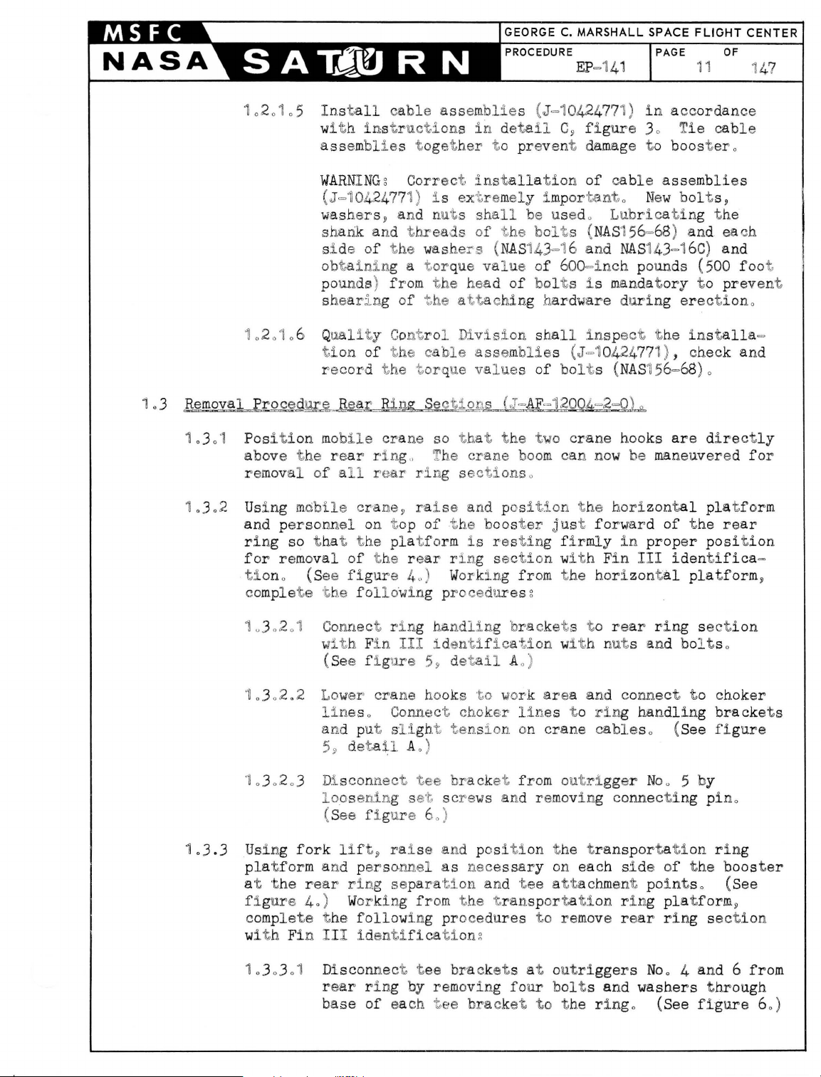
ter just forward
ting firmly
tio
n with F
rom
t he horizont
in
in
s g
ring
t he installa
are directly
be
maneuvered for
zontal
of
prop
III
identifica
al
bolt
s,
g t he
) and
t o preven't
erectiono
)0
pla
t form
the
rear
er
position
platform
=
=
~
1
.3.3
10
302
'~
.302
10
30203 Di
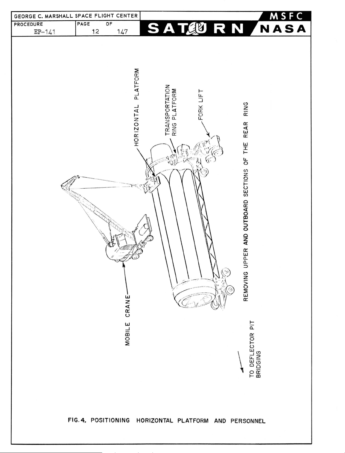
Using
pla
t f
1 Connect ri ng
0
wi
th
F
in
.2
Lower
1ine
and p
loosenin
fork
orm
and perso
(See f i g
5
~
scon
(S
ee
lift~
ure
crane hook
s o Connect choker
ut sli
deta
il
nect
g s
fi. gur e 6
ra
handling 'bra
III
iden
59
ght
A 0 )
tee
et scre
0)
i se and p
nnel
as
at 'the rear rlng separat,;i
f i g
ure 40) Working from
c
omplete
wi
t h Fi n I II
10303
t he following proce
identif
01
Disconnect t ee
re
ar
ri ng by removing
base
of
each t ee
ica
t iong
t i fica t,
detail
s ,
to
ion wit
A 0 )
work area and conne
line
ten
si on on
bracket fro
ws
and re
osition
nece
ssary
on and
t he t
tee attachment point
ransportation ring
dures
bracket
s at o
four bol
bracket
cket s t o
rear
ring
sec t
h nuts and bolt s 0
ct
to
s t o
ring handling
crane
cable
s o (See figu
m outrigger Noo 5 by
moving conn ecting pino
t he t
ransportati
on each si de of
on
the
s o (See
p
latf orm
to remov
utri
e re
ggers
ar
ring sectio
4
No
o
and 6 from
t s and washers t hrough
to
t he ringo (See f i
ion
choker
brackets
re
ring
booster
~
n
gure 60)
GEORGE C. MARSHALL SPACE FLIGHT CENTER
PROCEDURE
EP
=141
PAGE
OF
12 147
::E
0::
o
LL
I-
«
0..
--.l
«
I-
w
z
«
0:
U
W
--.l
Ql
o
::E
--.l
l-
LL
::J
~
0::
o
LL
\
(.!)
Z
0:
0:
«
w
0:
W
I
l-
LL
o
(/)
z
Q
I-
U
W
(/)
o
0:
«
o
Ql
~
:)
o
o
z
«
0:
W
0..
0..
::J
(.!)
Z
>
o
::E
w
0:
I-
0..
0:
o
I-
U
W<!)
~Z
W-
og
00:
I-Ill
FIG.
4.
POSITIONING
HORIZONTAL PLATFORM
AND
PERSONNEL
PROCEDURE
EP=141
FLIGHT
OF
13 147
.
CHOKER
CENTER
LINE
CHOKER
TYPICAL
LINE
\ I
~
;
)""-IJ-AF-12004-2-01
ASSEMBLY
HANDLING
IJ-I04244401
F.:OR
BRACKET
ALL
REAR
RING
RING
RING SECTIONS
FIG
. 5 REMOVAL
AFT
VIEW LOOKING
OF
TRANSPORTER
FORWARD
REAR RING SECTIONS
GEORGE
PROCEDURE
C.
EP
MARSHALL
-141
SPACE FLIGHT CENTER
PAGE
OF
14 147
(J"AF-12004 -2"17)
SCREW
ROTATED
180·
) B(AF-12004-2"3)
,
~
C6~~ECTING
~
~
---
·TEE
BRACKET
D(AF"12004-2"2)
TYPICAL
FIG.6 REAR
DETAIL
AT
OUTRIG
RING
SECTION ATTACHING
A
GERS NO
.2.4.6
POINT
AND
S
8
1.303.2
Remove
holes
holes
t he 4!=
of each
on opposi
screws t o
di sco
l ocat
of
are
rear
r i
and
nnectin
NO
TEg
or (A=AF=1
each ring
c
onn
ring
ng
at
locators
One 4!=
ect,ed~
each splic
sections o
inch
scr
ews
ring sectiony inser
te
si de
of
pull locato
g pos
inch
rs
(A=AF=1
iti
ono (See fi g
screw (J=AF=1
2004=2=14)
section; t
herefore,
one screw i s on t he
and one s cr ew i s
e j o
into
(A=AF=1
2004=2=14) rema
(J=AF=
12004=2=18) from
t t
hese
ring sections
2004=2=14) t o t he
ure 60)
2004=2-18) and one
are
loca
t ed
when
forward
on
t he aft
Screws
(J=AF=1200
in wit h t he
screws
in
, and t i ght en
in
t he end
t he
ring
sections
side
side
of
of
t he
4~2~18)
ring
end
hole
t he
rear
1
.3.4
103.3.3 Dis
connect
ti
on from
6 by remov
six
screws (J=AF=1
5 and 60)
1
0303
04
Co
nne.d tag
iden
t ifica
work
ing areao Use tag line
men
t 0 (See f i
10
3.3.5 Disconnect r
ion wit h F
t
lines
10
30306 Using
p
Us
ing
fork
and
personne
section wit h
from t he t
pro
cedur es g
10
3.4
.1
Con
Fin
f i g
from mobile cra
mob
er
sonnel
lif
t , raise
l t o a hei ght
Fin
ranspor
nect
IV
ure
rear
ring sectio
rear rin
in
g t
wo
g s
barrel
2004=2=17) at
line
tio
to
r e
n and hoi st
gure 50
ing handling
in
III
i dent i f
ile
crane, lower
t o
the
gro
und 0
and posi t
as
nece
IV
i d
entification.
tation ring pla
ring
handling
identification
5. )
n with Fi n
ecti
ons at out ri
nut s (J=AF=1
ar ring secti
off
of
t o cont
)
brackets
icatio
ne hooks .
horizon
ion transporta
ssary
for
(See
tform, compl
bracke
with
t s t o r ear
bolts
III
identific
ggers
No
. 4 and
2004=2=6) and
each
boost,er
end. (See
on w
ith Fin III
and lower i nt o
rol
swinging
from
rear
ring
figures
move
sec
n and remove choker
tal
pl at form and
t i
on
ring
removal
figure 4.)
ete
t he
pla
of
rear
Work
following
i ng
ring sectio
and
nut
s.
(See
a-
-
=
tform
ring
n with
1
.3.4.2
1.3.4
Using mobil e
to
work
03
Connect
ri
ng sect i on wit h F
t
ension
area
cho
on
crane wit
and con
ker
l i
crane
h t
wo
nect
nes
t o ring hand
in
IV
hooks,
t o choker
i d
enti
lower
lineso
ling
bracke
fication and put
cables. (See figure 5.)
crane
t s on
hooks
rear
sligh
t

GEORGE C.
PROCEDURE
MARSHALL
EP=141
SPACE FLIGHT CENTER
PAGE
1
.3.4.4
OF
16 1
Disconnect
47
outrigger
t
ee.
Remove
at out ri gger No. 8. (See
tee
No.7
two
bracket
from
by removing
bol
t s only from base
rear
ring
four
bolts
figure 6.)
section
from base
of
t ee
bracket
at
of
1
.3.4.5
10
304.6
1.3.
4.7
1.3.4.8
1.3.4.9
NOTEg The
t ee
bra
until
erection
forces
Disconnect
t
ion
by performing
in
paragraphs 1
Connect tag
wi
t h
Fin
Lower personnel and t
fork
lif
hoisting
Wi
t h
personnel
lift rear
of
t he bOOster and lower int o working
crane.
Disconnect
ti
on
and remove choker
remaining t
wo
cket at outrigger
are
cables
obtained
rear
ring
are
from t he t
section
the
.3.3
.2 and 1
line
to
lower end
rv
identification.
ransportation
t and
rear
clear
ring
immediat e
section
positioned
ring
(See
section wit h
figure
ring
handling
5. )
bol
t s t hrough t he base
No
0 8
connect ed and
with
applicable
.3.3.3.
(See
free
t o
maintain a taut tag
Fin
brackets
lines
from mobile crane hooks.
will
remain
ower
and
Fin
procedures
of
rear
figure
ring
area
preparatory
of
booster
IV
identification
from
of
t he
installed
slight lifting
gantry
IV
identifica-
cranes.
outlined
ring
section
5.)
platform wit h
t o
.
line,
free
area with mobile
rear
ring
sec-
1
.3.5
103.4.10 Using
and
fork
lif
personnel
t ee bracket s from out
se
t screws and removing connecting
6. )
1.
3.4.
11
Lower transportati
t he ground with f ork lift.
Using fork lift, raise
form and
ring
Working
following
1.3. 5
1.
3.5
personnel
section wit h
t o a hei ght
Fin
from t he t ranspor t ation ring
.1
procedu
Connect
wi
th
figure
Fin
5.)
res
ring
II
:
.2 Using mobile crane wi
t o work
area
t , rai
t o a
and
II
se transpor
height as
riggers
on ring
position
as
necessary
Noo 6 and 7
pla
tform and pereonnel
transportation
neceSSary
identification.
platform
handling
bracket s t o
identification wit h
th two
hooks, lower crane hooks
and connect choker
tat
ion
(See
rear
bolts
lines.
ring
pins.
pla
and
disconnect
by
(See
tform
loosening
ring
for
removal
figure
4.)
, complet e t he
ring
and
nuts.
(See
section
figure
figure
to
platof
rear
(See
5. )

T
CENTER
147
1.3.5.3
1.
3. 5
1.
3.5. 5 Disconnect r ear ring sect
Connect choker lines t o
ring s
ension
t
04
Disconnect t ee
out r i
of
by
ecti
on
on
crane
ggers NOe
each t ee
bra
performing
wi t h F
t he app
in
cables.
brackets
2 and 3 by removing
cke
t.
paragraphs 103.3.2 and 10303.
1.3.5.6
1.
3. 5.7
figure 8 for
numbers
.)
Connect tag l i ne t o lower end
Fin
II
ide
Inser
t t
section wit
and
secure tee
bol
t s . (See
NO
TEg The t
bracke
t at out r i
t he er ection
for
ces
are obtaine
identification
ntifica
wo
barrel nut
h Fi n I
brack
fig
wo bol
cables are connecte
t iono (See
identification at out r i
ur e 6
t s t hrough t he
gger
d from t he t ower and gant
ring handling bra
II identification
(See f i gu
from
rear ring sections at
re 5.)
four
(See f i
gure 6.)
ion wit h Fi n
licable
pro ced
30
of
Fin
of
ure
(See
Li nes and outrigger
rear ring
figure
s (J=AF=12004=2=6)
et
t o
rear ring
0)
base
Noo 2 w
ill
r emai n
d and
cket s on
and put
bol
II
identification
sligh
t s at
s outlined
figure 70)
section wit h
5.
)
in
rear
ring
gger No. 2
section wit h t
of
t he t ee
installed unt
slight
lifting
ry
cranes
rear
t
base
in
(See
wo
il
o
1.
305.8 Lower pe
fork lif t a
hois
t i ng
10
30509
Wi
t h pe
lift rear ring sec
of boos t
crane
1.
3. 5010 Disconnect
t
ion
10
3050
11
Using
pe
rso
bracke
screws
1.
305.12
Low
er pe
wi
t h
ransporter ont o t he
t
NO
TEg The aft end
hree
t
ring
No
o 2 and 8 at out
are sti
wo
of
t
sections stHl
rsonn
el and trans
nd cle
rear
rso
nne l positioned t o maintain
ar
ring sec
t i on with Fin
er
and lower i nt o worki
imme
t i
portat
dia
t e
on
free
ion
ring
area
preparatory
of
boos tero
II
i d
ng
area wit h mobile
0 (See figur e 50)
ring handling bracket
s from
and remove choker lines from mobi
fork
lif
t~
raise t
nnel
t o a hei ght
t s from out ri ggers
and r e
fork
points
moving conn
rsonnel
l i ft and
~
and t
t ee
brackets Noo
section with Fin I identifica
riggers
ll
connect ed t o t
t he four bolt
install
ransportati
as
necessary
Noo 3 and 4 by
ectin
g pins o (See
ransportation ring
clear
the
area
deflector pit
of
t he boost
er
1,
No
o 2 and 8,
heir
out
rigg
s t hrough t
ed o Tee
heir
bracket Noo 1
on r i
and di sconnect t
preparatory
bridgingo
is
2 and 8
t i on o Tee
er beams and have
base
pla
t form wit h
t o
a taut t ag l i
enti
fication
rear
l e
crane
ng
ring sec
hooks
pla
tform
loosening set
figure 60)
pla
t form
to
now
resting
of
t he
bracke
respe
ctively
t o t he ri
is
ne,
free
·=
and
ee
moving
on
rear
t s
y
ng
inta
o
ct
GEORGE
PROCEDURE
C.
EP
MARSHALL
~141
SPACE FLIGHT CENTER
PAGE OF
18 1
47
TEE BRACKET
(D-AF-12004-2-2)
(J-AF-12004-2-8)
SCREW
-~
,
WASHER
(J-AF-12004-2-7)
NOTE: OUTRIGGER 8 CONNECTING
PIN OMITTED
FOR
CLARITY
.
SET
SCREW...::...J
(J-AF-12004-2-10l
l-
lrl1!
~
FIG. 7. REMOVAL
OF
REAR
RING
SECTION
AT
OUTRIGGER NO.2
U>
b
z
a:
w
<.!)
<.!)
r--.
b
z
a:
w
<.!)
<.!)
a:
I-
::>
0
CD
b
z
a:
w
<.!)
<.!)
PAGE
OF
19 147
10
b
z
a:
w
<.!)
<.!)
a:
I-
::>
0
~S
<.!)
z
0:
z
0
i=
~
a:
0
0..
en
z
<I:
a:
Il-
LL
<I:
~
b
z
a:
w
<.!)
<.!)
a:
I-
::>
0
f()
b
Z
a:
W
<.!)
<.!)
a:
I-
::>
0
b
z
a:
w
<.!)
<.!)
a:
l-
::>
0
b
z
~H
LL
0
a:
<t
~
a:
0
LL
<.!)
Z
:lI::
0
0
...J
~
W
:;:
l-
LL
<t
FI
G.
8 I
DE
NTIFICATION
OF
FIN LINE AND
OUT
RiGGER
NUMBERS
GEORGE C.
PROCEDURE
MARSHALL
EP
=141
SPACE FLIGHT CENTER
PAGE 2 OF 1
0
47
20
10306
10307
10
308
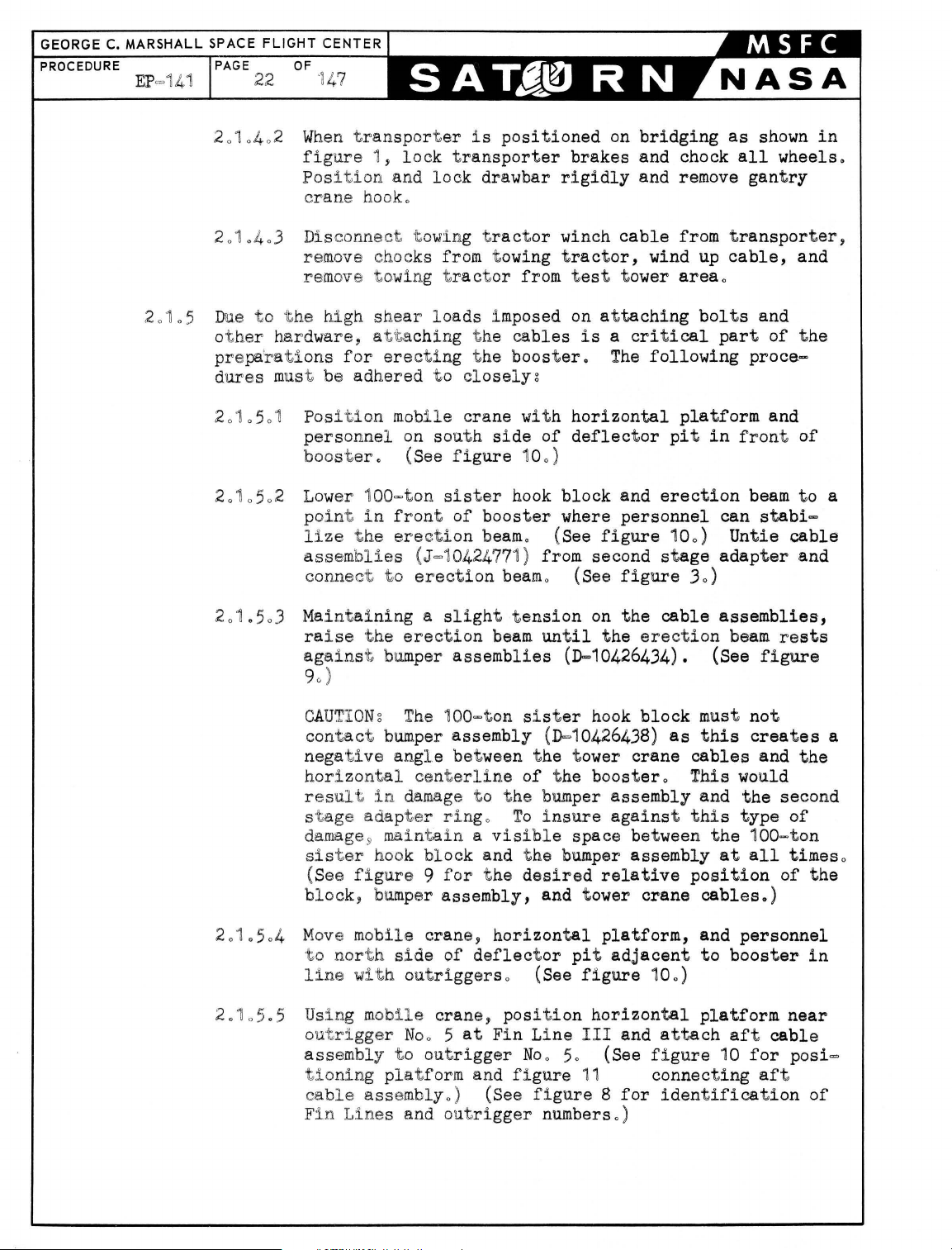
ERECTING
2
01
Pos
2
0101
and wil l not be
connec t ed and
th
e t
ower
and gant
t o be t
adap t
Clean mating
wi
t h
dry~cleaning
owed
er
is directl
surfaces
solven
accordance wit h paragraph 302
MIL-P=11
cation
Immerse attaching
preserv
Move ring
or
BOOSTER
iti
oning T
Using gant
pla
6 and
MIL
-C=1
ati
ve
details
equivalen
o
ransporter
ry
t form
of
apply
6173, t o mat
hardware
lubricating oil ,
t o adequat e st orage
t , and cover w
and A
crane
static
~
t es t t
disconnected unt
slight
t o a
lifting
ry
crane 0
position
y under t he t
of
P-3
rear
t~
corrosion
ring
Federal
01
ing
surfaces
for
of
rear
Military
ith
a t
arpaulin
tta
ching Erect
place erection
ower
o
il
erection
forces
are
Transporter
where t he second
ower
crane
cables
obtained
is
now
stage
o
segment s and tee bracke t s
Specification
Military
prevent
ive,
p-s=66
1,
Specification
Military
Specifi-
o
ring
segment s
Specification
area,
place
in
P-9
MIL-L
on
cross ties,
0
ion
beam
Cab1es
(J~10427055)
g
on
load
are
from
ready
in
=6440
10
2 Using t
2
0
t he l oad
t he 100=t
st
de
20103 Place
cra
2
0104 Using t owing t
boost
ower
pla
on
op
(C=10423817) , and screw
tail
Bo)
defl
ne
o
er
as
deflector pit
t
ractor
portero
it
from
l
et out
in
Position towing tractor
i n a dl
def
lect
sufficient slack
of transporter , and pos
bridging
as
crane,
t form and connect
sister
lower 1
00=ton
block and
sister
the
sister
(MS3530
ect
or pit
ractor,
close
bridgingo After
horizontal
bridging
as
poss
over
position
ibl
e t o and
pos
ition
t he t
locking
, disconnect
on
rect line with transporter
or pito Secure towi
in
ng tractor with chock
winch
ition transporter
follows
Using t owing
onto deflect
second
d
irectly under t
g
stage
t
ractor
or pit
bridging
adapter i s
he tower
winch,
block
erection
hook wit h
1=11
1) 0 (See
deflector pit
ransporter
in
alinement wit h t he
the
t he south
at a
and
sister
beam
(J=10427055)
pin (C=1
figure
using
carrying
drawbar
it
from
side
on
the
of
convenient
0423816),
gant
t he towi
deflector
dis
blocks,
cable, attach
on
carefully
t o a
24 inches
cable
deflector pit
pull transporter
position
short of
where t he
being
t o
crane 0 (See fi gure 10)
hook t o
9,
ry
t he
trans-
t ance.
fron
to
ng
t
NO
TEg
hori zon
Use
tal
gant
ry
crane t o hold t
position.
ransporter
drawbar
in

= _ '
_0
r~
O
__
y-
~
A / ' '
~
--£
~'I .-=~"
"
~
r
-
o-"
~
4-
~
"-
"
TON
100
SISTER
HOOK
BLOCK
ERECTION
BEAM
(J-10427055)
"-
f11
- -
' -
BUMBER ASSY (0-
2-BUMPER
~~~~
]
!
~
I
I
10426438)
(0-10426434)
PIN (C-10424412)
~424
:
~)
PAGE
21 147
1\~,\
A
/-
GANTRY
\
).1
BLOCK
https://manualmachine.com/-
AFT
r ASSEMBLY
Il
(0-10423292)
111
(
CONNECTING
{/'
(~~~424657)
1
i~
A
__ 1
~
OF
CRANE
ASS'Y
CABLE
f---------
CONNECTING
TYPICAL
__
NOTE:
BUMPER
NEVER
HAS SOME VISABLE
"-----
------
-----
_____
ERECTION
~
~
·
PIN
----~
FORWARD
TWO
__
.. ______________
ASSEMBLY
BE
LESS THAN
~:
CABLE ASSEMBLY
(J-10424
PLACES
10426438
SPACE
(J-10427055)
~~
ERECTING
771)
IS
90°
FROM
BETWEEN IT
--
2-CABLE
ASSY
(J-10424771
~1
_
~
~
-
-----
f~-
---.---
BEAM
COTTER PIN
--
:::~
J
-
I
_
__________
NOT
DESIGNED
THE
HORIZONTAL CENTERLINE
---
AND
------
FIG.9 ERECTION BEAM INSTALLATION
...
J
~
__
TO
RESIST
EXCESSIVE LOADS,
THE
BUMPER ASSEMBLY_ C
--------"
._.-
--
L--::::::
\
~
[
OF
THE
--
-
---------------
-----.
BOOSTER
,
TOWER
CRANE CABLES SHALL
SO
THAT THE SISTER
8
HOOK
GEORGE
PROCEDURE
C.
MARSHALL SPACE FLIGHT CENTER
EP
=141
PAGE
22
OF
"1
47
20105
2010402 When tran
fig
ure
1,
Position
c
ran
e hook.
2010403
Disconnect t owing
remove chocks from t owing
remove towi
Due to
ot
prepa'rations
dures
2
0"10501
her
the
high
hardwar
mus
t be
Pos
shear
e, at'ta
for
adhered
ition mobi
personnel
booster.
2
010502 Lower
100=ton
point in
l
:l.ze the
201.5
03
assemb
conne
Mai
ra
lies
ct
ntai
ning a slight
ise the
against bum
90 )
sporter i s
lock
and
lock
tran
drawbar
positioned
sporter
tract
ng t
ractor
l oads imposed
chi
ng
the
erecting the
to
closelyz
l e
crane
on south
(See
side
figure 100
sister
front of
booster
erection beamo
(J=1
0424771 ) from second
to
erection
erection
per
beam
assemblies
or
from t
cables
booster.
with
of
)
hook
(See
beam
o (See
tension
until
on
bridging
brakes
rigidly
winch
and chock
and remove
cable
tractor,
est
tower
on
attaching
is a critical
The
horizontal
deflector
block
where
and
personnel
figure
wind
following
pit
erection
100)
stage
as
from
area
transporter,
up
cable,
o
bolts
part
platform
in
can
Untie
adapter
figure 30)
on
the
the
cable
erection
assemblies,
beam
(D-10426434). (See
shown
all
wheels.
gantry
and
and
of
the
proce-
and
front of
beam
to
stabi=
cable
and
rests
figure
in
a
2
0'10
2.105
CA
UTIO
Ng
The
contact bum
per
negative ang l e between
horizontal
res
ul t in
centerl
damage
stage adapter
darnage9 maintain a visi
sister
(See f i
hook
gure 9 for
block, bumper
504
Mov
e mobile
t o nor t h
side
line with outriggerso
.5
Using m
o
utrigger Noo 5
assembly
tioning
ca
F
in
ble
Line
obUe
to
pla
tform and
assemblyo
s and out
100=ton si
ster
hook
assembly (D-10426438)
the
t ower
ine
of the boostero This would
t o
the
bumper assembly and
ringo
block
assembly,
crane,
of
crane,
at
outrigger
) (See
To
insure
ble
space between
and t he bumper assembly
t he
desired
and tower
horizontal
deflector
position
Fin
pit adjacent
(See
figure
horizontal
Line
III
Noo 50
figure
11
figure 8 for
rigger
numberso )
block
crane
as
cables
must
this
not
creates
the
against this type
the 100
at
all
relative
platform,
crane
position
cables.)
and
personnel
to
booster
100)
platform
and
(See
attach
figure
aft
10
for
connecting
identification
and
second
of
=to
times
of
near
cable
aft
a
the
n
o
the
in
posi=
of
STATIC
TEST
TOWER
PROCEDURE
EP-141
PAGE
23
STATIC
TEST
TOWER
FT
ASSEMBLY
OF
CABLE
147
TOWING TRACTOR
(M-
26)
DEFLECTOR
PIT BRI DGING
TRANSPORTER
DEFLECTOR
HORIZONTAL
PLATFORM
MOBILE
HORIZONTAL
PLATFORM
SATURN
BOOSTER
TRANSPORTER
DEFLECTOR
PIT BRIDGING
CRANE
FIG.
STEP I
ATTACHING
10
ATTACHING ERECTION BEAM AND CABLE ASSEMBLIES
CABLE
ASSEMBLIES
TO
ERECTION
BEAM
ATTACHING
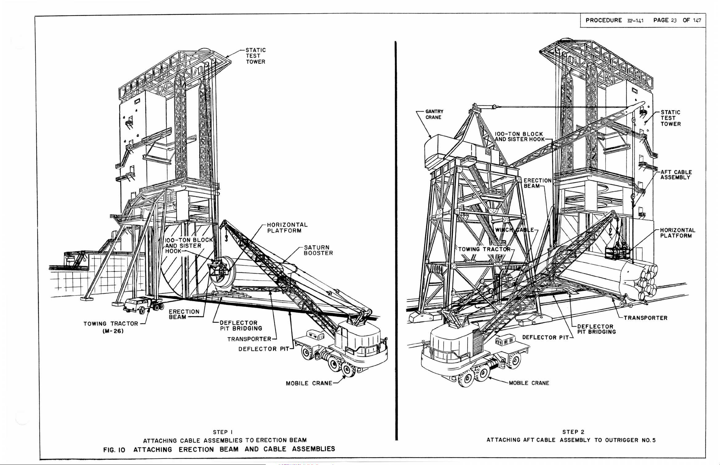
AFT
CABLE ASSEMBLY
STEP
2
TO
OUTRIGGER
NO.5
~
GANTRY
BLOCK
CRANE
ASSEMBLY
- - - -
---
-
---
CONNECTING
---
PIN~
~
--------AFT
.
~
...
-----
CABLE
ASSEMBLY
(0-10423292)
COTTER
PIN
CONNECTING
(0-10424657)
NUT
OUTRIGGER-------.y-
LINK
(DOG
BONE)
~
.
~
FIG. II. CONNECTING
@;
AFT
~
CABLE ASSEMBLY
CONNECTING
PIN
A
PROCEDURE
EP-141
PAGE
26 147
OF
201.5
2.1.5
2
.1.
508 Using
2.105
2.1.50
.6 Lower gan t
assembly
NOTE:
lifting
ry
gant
forces
t he boos t
ry
t o
Prior
forces
cranes
should not,
er
ware yet t o be r e
07
Remove
aft se
set
Connecting
figure
ring
of
.9
Remove two
bracke
large
t screws
screw t hrough
pin
60
)
fork
pla
lif
t form and
t he boos t
rema
t at out ri
10 Disconnect t ee
loosening
(See
figure
set
crane
block
to
as
Bal~lok
er
block
assembly
assembly. (See f
t he
following
must be
obtained
t o support t he
however, be
t hi s would
moved
in
t ee
base
remains
t ,
raise
cause
from t he
pin
and
bracke
of
t he t ee
in
out
and
position
personnel
at outriggers
ini
ng bol
ggers
brackets
t s t
No
2 and 8.,
o
from outriggers
and at
igure 100)
proceduresy substantial
from t he tower and
booster
great
.
enough t o
binding
forward
loosen
t at out
rigg
t he
rigger
is
t o remain
er Noo
t he transportation
as
necessary
No.2
hro
ugh b
and 8
ase
(See f
screws and removing connecting
60
)
tach aft
The
lifting
of
t he
and
rear
forward
No.1.
10
(See
on
each
of
rear
of
each tee
igure 60)
No
2 and 8 by
o
lif
hard-
fixed
pins.
cable
t
rings
and
The
.
side
ring
o
.
NOTE:
lower
porter.
2.1
05.11 At
tach two
NOTE~
equal,
201.5.12
Place
Lower
201.5.
13
fork
Remove
lif
porter
2.1.5.14
Clean mat
brackets wit h
tion
p=s=661,
Military
corrosion
MIL=C=
01.5.1 5 Immerse at
2
bracke
Specification
Boost
section
approximately
tee
personnel
er retai
tag
Tag
lines
bracke
t and cle
of
rear
lines
t o be
t s on t
and t
ar
ns
ring
t o
75
ransportati
immediat e
support clamps from
. (See
ing
figure
surfaces
dry
cleaning
in
accordance
12
of
Specification
preventive,
161
73,
taching
t s'
in
t o mati
P-9
preservative
MIL
Military
ng
hardware
=L=644.
the
horizontal
remains attached
each
outrigger
1=i
nch diamet
feet
long
o
ransportation
on
area
forward
0)
support
clamps and
solvent,
with
paragraph
MIL
=P-116 and
Specification
surfaces
for
0
support
lubricating
position
Noo 3 and 70
er
hemp
ring
ring
near
ring
pla
rear
and
Federal
apply
clamps and
oil,
and
t o t
rans=
pla
rope,
tformo
or
tform wit h
ring
o
trans=
tee
Specifica=
3.2.1
of
P=3
tee
Military
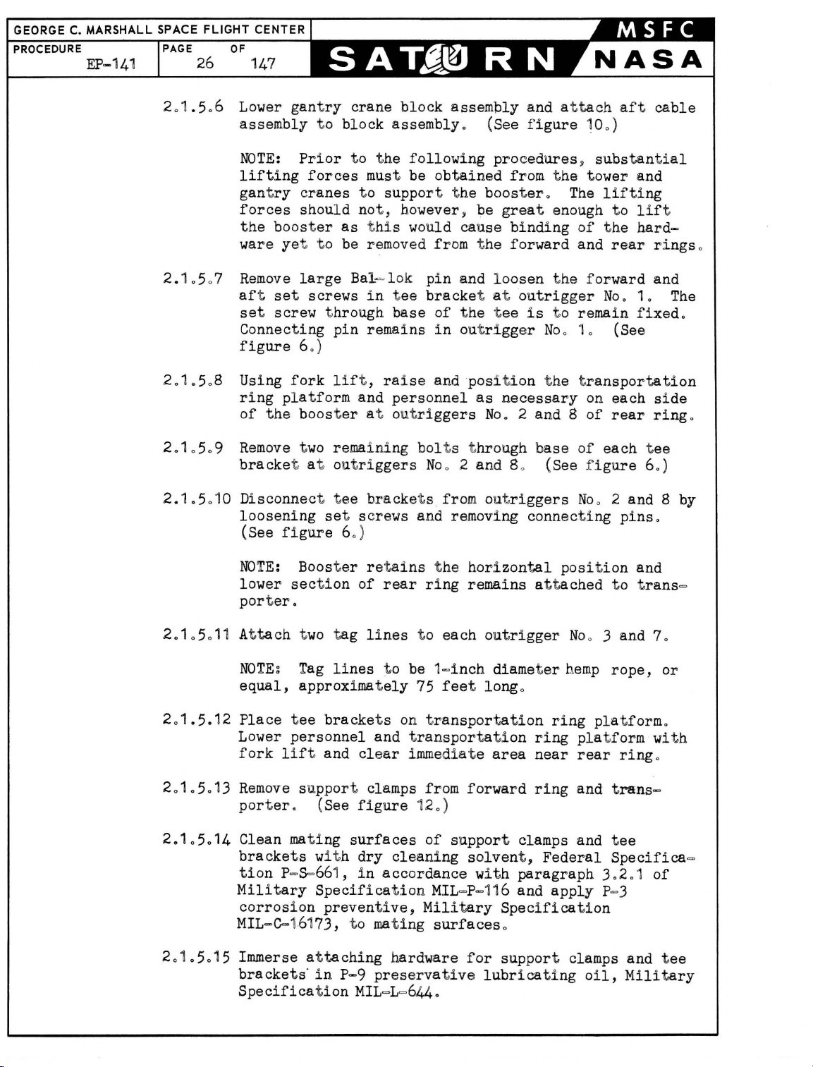
GEORGE C.
_-
________ . (J-AF-12004-3-0)
FORWARD
RING
HOLDDOWN
(J-AF-12004
FORWARD
ROLLER -
- 4-36)
--1
V
=
VIEW
LOOKING
DETAIL A
AFT
-HOLOOOWN
BRACKET
(J-AF-12004-4-31l
Y/~
CAP
~
(J-
1----
SCREW
i-II
NC 8 REa'o
8
AF-12004-4-32)
TRANSPORTER
FIG.12
FORWARD
SUPPORT CLAMPS

GEORGE C. MARS
PROCEDURE
202
Removing Boost
L SPACE
PAGE
201
0
FLIGHT
28
5016
er
CENTER
OF
147
Move
storage
c
ov
from
support clamps and t ee
area,
er
with a tarpaulin
Transporter
place
and
on
Positioning
bra
cross ties,
0
cket s t o adequat e
or equivalent, and
on
Tow
er Th
rus
t Ringo
2.201
Have
ment of
figure
bar
20
20102
2020103 Using t
202
02 With tower
booster
ring
20203
Using towing
Clean and
ou
tl
men
hold
boost
13
0)
Using t ower
lifting
above t he
rear
Gonne:c
using tow
the
free
This st.
of
crane
off transporter
section
o
preserve transporter
ined
in
paragraphs
each
er
as
of
it
force
bottom set scr ew
out
rigger
t towing t
bar
rac
t orjl
connecting
In t he
l9.b.ilizes
transporter
and
gantry cra
(See
figure
tractor,
t he
four
is
raised
cra
ne and gant
t o
tag
from t he
raise boo
lin
ry
ster
es
to
transporter o (See
crane~
approximately t=inc
located
No
10
o
ractor
0
(See f i
t o t he aft end
move transporter
pin
in
out
slot of
t ee
booster
prepara
bracket
rigger
gur
es 13 and 140)
f orward
No
at out
t ory t o liftin
o tSee f i gur es 13 and 14
ne lif t i ng
to
a hei gh't that wi
sim
ll cle
130)
remove tran
10205
sporter f rom
us i ng app
and
10
2060
licab
prevent undue move=
appl y a
slig
ht
h
in tee
bra
of
t ransporter
cket
at
or aft unt i l
0 1 i s
floating
rigger Noo
10
g clear
0)
ultane ous
ar
stat
le specifi ca
ly~
hoist
t he r e
ar
i c test ar ea
tion
s
o
20204
Wi
t h
the
booster still
t
ransportery remove
out
rigger
No
20205 Using tower
202.6
202,.7
20
2.8
gantry
maneuver
Using mobile
outrigger,
at
No
Lower
'
crane
Using tower
main
vertically
lines
position
Fin
if
5
o
horizontal
and
load
to
crane
0 (S
Line
conditions
horizontal
platform,
personnel
i t a few
in
horizont,a
pin
in
out
rigger
0 1
if
crane
t o
ee
crane
cond! t
~
hois
sta
bi lize booster and take up sl ack
figure
and hori zontal pl at form t o gai n
ions
t boost
150)
warra
er into
disconnect aft cable ass
1110 (See f i
gure
150) A
warranto
pl at form
pla
craney hoist booster
move
over
opening
on main
fee
t above t
using mobile c
tform from stat i c test H
t o a he
boost
of
er hori zon
main
load
load
pla
hrus
l
posi
t.i
on~
but free
No
10
At
o
nt
0 (See f i g
vertical positi
tach tag line t o
ure
14
0)
ono
duri
access
embly from outrigg
er Noo 5
ttach tag line t o outr i gg
ran
e'. Re
ight suffici
tall
pla
tform, transfer tag
t form; lower boost
move mobile
rea
o
ent
y t o a posiUon
er
t ringo (See f i gur e
of t,he
Use
ng
t o
to cle
and
150
)
er
ar
TOWER
CRANE
HOIST
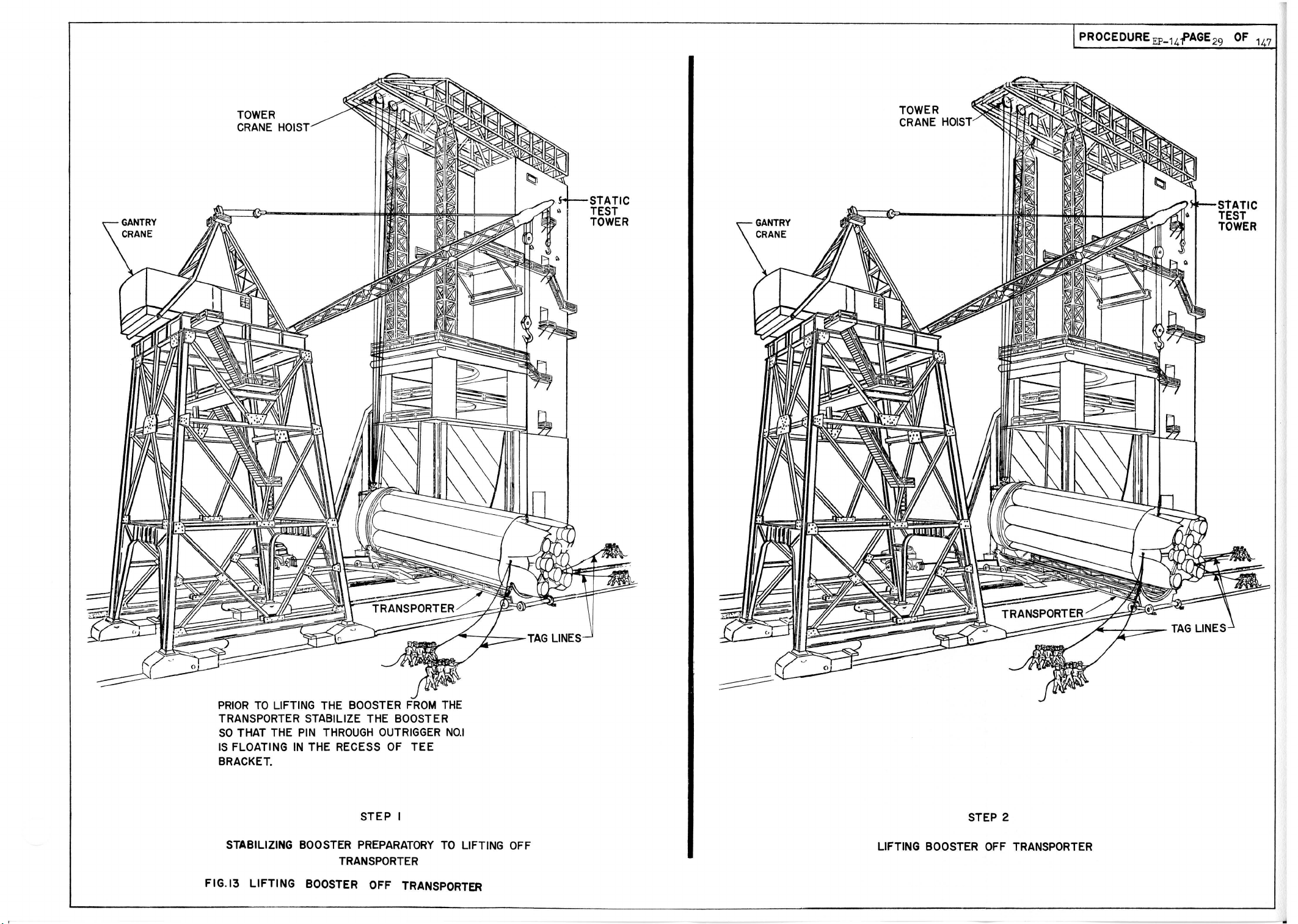
PROCEDURE
EP-14f
AGE
29
OF
stATIC
TEST
TOWER
147
PRIOR
TO
LIFTING THE BOOSTER
FROM
TRANSPORTER STABILIZE THE BOOSTER
SO
THAT THE
IS
FLOATING
PIN
THROUGH
IN
THE RECESS
OUTRIGGER
OF
TEE
BRACKET.
STABILIZING BOOSTER
STEP
PREPARATORY
I
TRANSPORTER
FIG.13
LIFTING
BOOSTER OFF TRANSPORTER
THE
NO.1
TO
LIFTING OFF
STEP 2
LIFTING BOOSTER
OFF
TRANSPORTER

OUTFllGCiER
[\10.
1
PIN CONNEC
(B-AF-12004-2-3)
FIG.14. BOOSTER
TING
STABILIZATION
PREPARATORY
TO
LIFTING
OFF
TRANSPORTER
 Loading...