

Page 1
HANDLING,
TRANSPORTING
AND
ERECTION
SATURN
INSTRUCTIONS
S-l
STAGE,
SA-1
,
J
:
....
GEORGE
."
C.
MARSHALL
SPACE
HTTP://HEROICRELICS.ORG
HUNTSVILLE
FLIGHT
ALABAMA
CENTER
Page 2
TITLE
Handling, T
Erect
ion
ranspor ing,
Inst
ructions, Sat urn S
Stage
~
SA
=1
And
T
ABLE
=1
OF CONTENTS
GEORGE
MARSHALL
SPACE FLIGHT
PROCEDURE
DATE
PAGE
1
1
OF
c.
CENTER
147
Paragraph
LIST
INTRODUCTION
10
OF
CHAPTER
PREPARING
ILLUSTRATIONS
0
000
000
Q
I T
RANSPORTATION,
BOOSTER
VOOOGOOOOOOOOOOOOOOOO
<:)
I,)
U 0 0
(J
0
HANDL
FOR
ERECTION
000000
0 0 0 0 0 0
ING,
AND
ooooooooo
101 Positioning Transporter (J=AF= 2004)
102
"103
2 0 ER
2
2~2
30
Installing
and
Removal
ECTI.NG
01
Posit~oning
Removing
T
hrus t Ring
REMOVING
Bumper
Two
Cable Asse mblies (J=1
Procedu
BOOSTER
Transpor t
Booster
BOOSTER
Assembly (D=
re
Rear Ring Sec
0 I,)
(J
0 0 0 v 0 0 0 0 0 0 0
er
from T
0,)
a 0 0 0
()
0 0 0 0 0 0 a 0
FROM
TEST TOWER
10426438) ,
0424771)
'ti
(.0
(J 0 (J
and At
tachin
ransporter
()
U 0 0 0 0 a 0 0 0 0
ons (J=AF91200
0 0 u 0 0 0 0 0 0 0 0 0 0 0 0 0 0 0 0 0 0 • a 0 0 0 0 • 0 0 Q
and Pos
Ovooooouooooooooooooooo
O .
OOOCOOOOOQO
I)
0 0
00000.)
0 0 0 0 0
ERECTION
o
oooooooooooooooouoooooooooooo
AT STATIC TES
oooooooooooooo
Two
Bumpers
oo oo
ooo
g Erection
itioni
(J
C.
0 0 0 0 0 v 0 0 0 0 0 GOO. 0 a 0 0 0 0 0 0 0
Page
OOO
OOOOOOOOOOOO
(.I
0 0
000
000000
o
ooopoooooooooo
(D=
. o o
oouoooooooooo
4=2
=0 000000000000000
0000
T T
OWER
10426434) ,
.
0 0
ooooo
(I
OO
O
000
000
o'o
I)
C 0 20
11
Cables 000000000000000 20
ng
on
Tower
(I
0 0 0 28
o
ooooooooooouo
35
3
5
7
7
7
7
3
01
Prepar
302
Removing
Trans
303
304
Installation
Removing
and
CHAPTER
10
PREPARING
1
01
Preparing
102
103
Positioning
Insta
(J
ing
Booster for
Booster from Towe
porter
Bumper
Two Cable
II
TRANSPORTATION,
BOOSTER
Servi ce St ruct
Tran
lli
ng
Beam
""",
1 0426668) 0 0
Removal
ooooovooo"oooo
r Thrus t Ring and
0 0 0
0.)
0 0 0 0 0 0 0 0 0 0 0 0 0 0 0 0 0 0 0 0 0 a 0 0 0 0 " 0
Proced
ure
Assem
Rear Ring Sect
bly
(D=1
0426438) , Two
Assemblies (J=10424771)
HANDLING9 AND
FOR
ERE
CTIO
N 00000000000000000000000000
ure for Er
sporter
Weldmen
()
0 0 0 0 0 u 0 v 0 0 0 0 0 Q 0 0 0 0 0
(J=AF= 2004 0000000000000000000 .
t (J=10426675) and Forward
ion
ERECTION
ecti
on
coo
o
ooo
ooooo
Pos
itioni
\.'I
0 0 0 0 0 0 0 0 0 0 0 0 0 0
s (J=AF=1
2004=2=0) 000
Bumpers
0000000000
AT
CAPE
ooocooOoooooooooooooo,ooo
0 0 0
I)
0 0 0 0 0 0 0
ooooooooooooo
ng
on
(J
0 0 0 0
ooo
0;1
0000000
(D=
10426434)
00 00
000.' 0 0000000000
CANAVERAL
00000
00000
00000000
oooo
000000000000
Sling
Assemblies
I;)
0 0 0 0 0 0 0 0 0 0 0 0 0 0 0 0 0 51
35
0 0 37
40
44
47
47
47
47
Page 3
EORGE C.
PROCEDURE
MARSHALL
EP=141
SPACE
PAGE
FLIGHT
CENTER
OF
2 1
47
TABLE
OF
CONTEN
TS
(Con
o)
Paragraph Page
104
105 Removal
:2
2
,2
30
40
4
4~2
Remova
0
EREC
TING
01
Posit
2
Removing
0
REMOVING
REMOVING
RING DET
.1
Removing
front Trans porter
Preservi
l Procedure Forward Ri
Procedure Rear Ring Secti
BOO STER
ioning
Booster
BOOSTER
RING
AILS
Forwa
ng
Forward and Rear Ring Deta
I)
0 0 0 0 0 0 0 0 0 0 0 0 8 0 0 0
Transport er and A
from Transpor t
FROM
LAUNCH
SECTIONS
AND ATT
WITH
ACHING
rd and Rear Ring Sect i ons w
I)
0 0
(.)
0 0 0 0 0 0 0 0 0 0 0 0
ng
Sectio
tta
er
PEDESTAL
ns (J=AF=12
ons (J=AF=1
(I
Q 0 0 0 0 0 0 0 0 0 0 0 0 G
ching Cab
and
Pos
les
iti
00000000000000000000000
2004=2=O)
0000000000000000000000000 64
oning on Launch
FIN I IDENTIFICATION
HARDWARE
0000000000000000000000
ith
Fin
4)
0 0 0
00
0 0 0 0 0 0 u 0 0 0 0 • 0 0 0 0 0 0 0 0
i!L
s and Attachi
004
=3=O)
000000
0000000
0000000000000000
OO
0 0 0 0 0 0 Q 0 0 0 0 0 " 0 0 0 e 0 0 0
Pedestal 0 72
00000000
AND
PRESERVING
ALL
0.000000000
I Ident
ification
ng
Hardware a 0
I)
I.) 0 0 0 0 0 0 0
54
60
64
0.
79
80
8D
eo
0 0
82
CHAPTER III
GENERAL
INSTRUCTIO
NS
FOR THE
8=1
T
RANSPORTER 0000
0000
000
0000
00
83
Page 4
LIST
OF
ILLUSTRATIONS
PAGE
OF
EP-141 3 147
Figure
1.
2"
3.
40
Positioning
Removing Doors and
Installing Bumpers
Positioning
Equipment at
Horizontal
5. Removal of Rear Ring Sec
6.
7.
8.
9Q Erect
100
11
• Connect
2.
1
Rear Ring Sect
Removal
of
Identification
ion
Attaching
ion Attaching
Rear Ri
of
Beam
Ins t
Erection
ng
Fin
allation
ing Aft Cable Assembly
Forward Support Clamps
Static
Plates
oooe
and Cable
Pla
tform and
ti
ons
Section
Line
and Out
Beam
and Cable Assemblies 0' 0000'
o.
0 0 • 0 0 • 0 • 0 0 0 0
Title
Test
Tower 0000
o o o
oooo
o
ooocooooooo
Assemblies
0.000 •• 0
Personnel
(J=AF=12004-2~0
Poin
ts
•••
000. 0. 0.00.0 •• 0,'0
at Outrigger
rigger
oeeoooooooooo
••• 00. o
Noo 2
Numbers
ooooo •••
••
0 ••• 0 0 0 0 • 0 0 • 0 0 • 0
•.•
0 0 0 • 0
•• 00. 0 •• 0
o
CJOOOOOClOOOO
••• 0 ••••
•••
• 0 •.
O O O O 9
00
•. 000.0 10
000000.00"00'.00..
)
0.0
00000.00 •••••
.'0
•• 0" 0 14
••• 0 .. 0 .....
0'0.0.00.00
oo
• • o
ooooo
00.0.
•• 0
ooeoo
0000000'0 0" 0 23
.•
0 . 0 0,' • 0 0 0 .' 0
••• 0 00
. 0 • • 25
•••
0 • • •
00
0.
..
oo
Page
8
12
13
18
19
21
27
13 0
14. Boost
15.
16
0
17.
18.
19.
20.
21.
22.
23
. Forward Ring Section Removal
24 .
Lifting
Boost
Positioning Boost
Preparing
Boost
er
Stabilization
er
in
er
Vert
Serv
ice Structure
off
Transporter
ical
Position
er
on
Preparatory
Positioning Equipment at
Preparing
Installa
ti
Boost
on
of
er
Beam
for
Erection 0 0 •• • •• 0 • •• 0
Weldmen
Removing Forward Ring Sect
Forward Ring
Attaching Aft
Section Attaching
and Forward
0 •• 0 • •
0000000
t o
Lifting
••••
000
..• 0 .•.•
0. 0 •• •• •• 0. 0. 0.0 0.· •
Support Bracket s 0.00 . 0
for
Erection
Firing Sit e 0
.000.00 •••
•••. 000. 0
•.
t and Forward
ions
(J=AF-12004~3~0) .~
Poin
t s
Procedures
Sling
Assemblies .000
•••
Sling
0 .
.0 .0
.... 00. 0 ••
••••
00
•• 0. 0000.000 •• 29
off
Transporter
0000
000
00
••
0. 0
•.••••..
. 0
••••••.
••• •• 0......
• . 0. 31
•••
•• 0 33
0 •• 36
0. 0
..
0 0 0 0 0 • 0 • 0 ••• p 0 0 0 0 . . •
Assemblies
0.
00
•••
00
00
••••
• 0.
•••• 00
.. 0 ••••• 00..
00
••
0' o . 00" 0
......
00
. • 00. 0
0 •• 0 56
00
48
49
52
53
55
57
65
Page 5
GEORGE
C.
PROCEDURE
MARSHALL SPACE FLIGHT CENTER
EP
,·,1
41
PAGE
4
OF
147
Figure
Connec
26
27
28
0
.
.
L
8-1
Removing
29. Booster-
30.
31 0 Rear Ri ng Support Cl
P
ti
ng
ifti
ng Boost
Stage
Af t Cable Assembly and
Pedestal
to-
ositioning
Erect
ing
er
off
Cen'ter-or-Gravi
0
III
0 .
000
Launch
Boost
LIST OF
Beam
Transpor
••
0.0
ILLUSTRATIONS
Ti t
le
and Forward
er
0
•• 0 ••••
ty Di agram
Positioni
Q 0 • • " 0 • • 0 e • • 0 II 0 . 0 0 0 .
(Con
Sling Assemblies
• 0 • • 0
••••••
ng
o)
• 0 • • 0 • •
Booster
....
Pedestal Orientation Diagram..
er
on
Support A
amp
s Q. 0 0 • 0 0 • ·0 u •
rms
and Holddown
••
0
••
0 •
III
0 • 0
••
0 •
•••••
••••
...
0 0
. ..........
Arms
•••
••••
0 •
•• ••
on
!oJ
00000
.0...
•
•
•• 0..
•••••
00.
• 0 • •
Launch
•••
" 0 0
••
...
....
III
•••
0 • • • • • • 81
Page
• • • 69
••
• • 71
00
. 75
..
..
68
77
78
Page 6
ER
Thi s
manual provide
erecting
and
chapt
II
ta
ers 0 Chapter
con
tai
ns
i ns
opera
ins
t i ng
Chapter I consi st s
sections,
va
tion
of
t he
Chapter
rear
pedes t
position
of tooling
rear ring sect i ons t o t he
II
ring
sections, posi t i oning and
al,
and
A complet e
T
ransporter
and Int
roducti
Equipmen
t ower and
por
t e
r, towing tractor
ranspor
t
handling
and i ncluding a
t e
at t he Cape Canaveral f
tat i on ring pl a t forms .
of
t he Boost er d
s t he necessary in
t he Saturn S
=I
Booste r
I cont ai ns instructi
t ruct i ons at t he
ins
t ructions
of
st ep=by=st ep procedures
i ng and erecting the
, pos
iti
oning
cons i st s
preserva
man
ual
of
t i on
con
taini
st ep=by=st ep
of tool
on i s inserted i n
ssential
t o proper ha
, gant
urin
INTRODU
~
ef
Cape Canaveral
for
t he Sat
t he Boost
Booster aft
erecting 'the Boost
i ng
ng ge
separa
neral inst
t e Tab l e
thi
s manual
ndling of
irin
g site i
ry
cra
ne, mobil
Sp
eci
al
g r e
mov
al
CTI
ON
st r uct i ons
fectivity SA
ons at t he
f i ri
urn
S=I T
ransporter
Boost
er
on t he t
er
i n t he
er sta
procedures
for shipp ing.
ructions
of
Con
t ent s ,
as
Chap
t he Boost
nclu
des t he fol
e c
rane, fork
hardware
and
erection.
assures
for transporting,
=1
and
is divided int o t
static tes
ng sit e.
t tower.
Chapter
.
for
r e
moving
t he
static test t ower ,
ransp
or t
er,
and
t i c test
for
for
firing
removi ng t he
er
from t he
t he Sat
List of
t er
III
.
er
at t he
lowing: trans
l i f t ,
safe
horizontal
and
handling
Chapter
III
rear ring
reassembly
.
forward
launch
urn
S=I
Ill
ustrati
static tes
efficient
hree
con=
pres
and
ons,
t
=
and
,
er -
Divi
T
his
sions
publ
0
i cat i
on
i s a
com
bin
ed
effort
of
t he M=
LOD, M=T
EST,
and M-
F&AE
Page 7

PROCEDURE
PAGE
OF
Page 8

CHAPTER
I
1.
PREPARING
1.1
1
Pos
1.1.
1.
.2
Installing
and
1.
1.2.2
TRANSPORTATION,
BOOSTER
iti
oning
1 Pos
r i ght
FOR
Transporter
iti
on transporter
angle
bridging
1.2
area
Lock t
around
(See
figure 1 for
ransporter
Bumper
Two
Cable Assemblies
2.1
Move tractor
boos t
Using
er
fork
personnel
(D-10426438) , t
(J-10424771) . (See
HANDLING,
TEST T
ERECTION
0
(J=AF=12004
on nort h
t o
deflector pit
at a di stance which
t he t
ransporter
the rel ative
brakes
and chock wheels .
Assembly (D-10426438).
(J-10424771~
and t
ow
bar
.
lift,
raise transpor
to a height necessary
wo
bumpers (D-10426434
figure 2.)
AND
OWER
)o
for
clear
ERECTION
side
of
and
aline
will
provi de
t he mobile
positions
Two
of the
tat
ion
for att
AT
STATIC
sta
tic tes
wit h
sufficien
of
Bumpers
forward
ring
aching
),
and
t t ower at a
deflector pit
t working
crane
and
fork
t he equipment. )
(D-1042643~
end
of
t he
pla
t form and
bumper assembly
cable
assemblies
)
lift
!
.
1.
2.1 .1
1.
2. 1. 2
1.201
.3
1.201.4
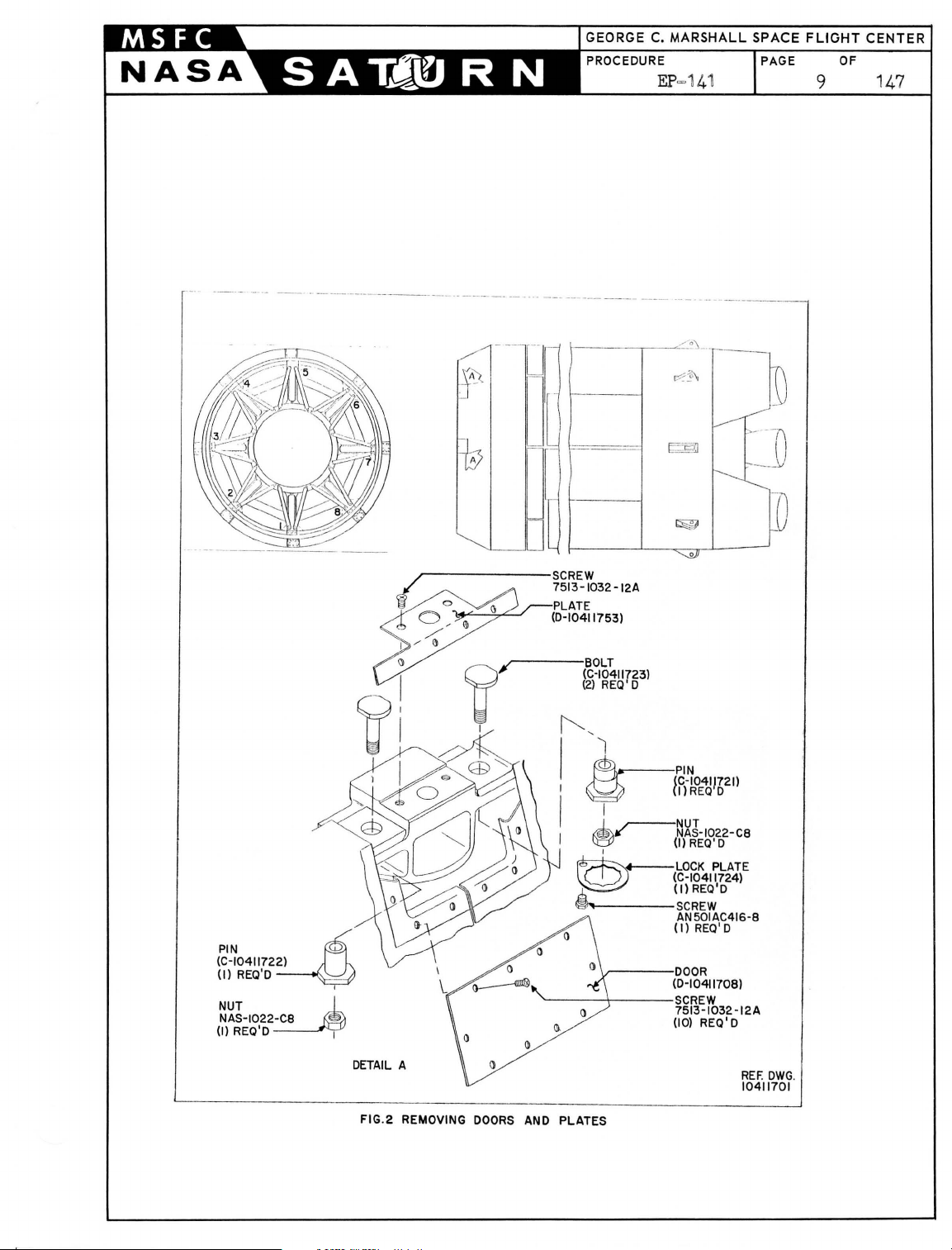
Remove
attached
adapter
doors
t o int
~o
gain
assembly attac
I=beams
Remove att
fairing
for
shown
NOTE:
and st
boost
No.3,
aching
t o second stage adapt
bumper
in
All
figure
assemblies
doors
oredo Th
er
has been
figure 2 for
Install
bump
wi t h detai l
Install
B
~
bumpers (D-10426434)
figure
3.
(D-10411708) and pl at
er
st age
access
hing
4,
fairing
t o bumper and
poi
nt s . Attaching
5,
6,
and 7.
hardware t hat
er
es
and second st
secures int
at at
and forward sli ng
2.
and a
i s hardwar e wi
erec
list of attaching
tta
t ed
ching
in
hardware t o be packaged
ll
be
t he test t ower. See
hardware.
er assembly (D-10426438)
A,
figure
3.
in
accordance
(D-10411753)
age
forward
poin
t s
ers
sling
are
tage
taching poi nt s
assemblies
installed aft
in
accordance
wi
t h
at
as
er the
detail
Page 9
PROCEDURE
EP
=141
PAGE
OF
8 1
47
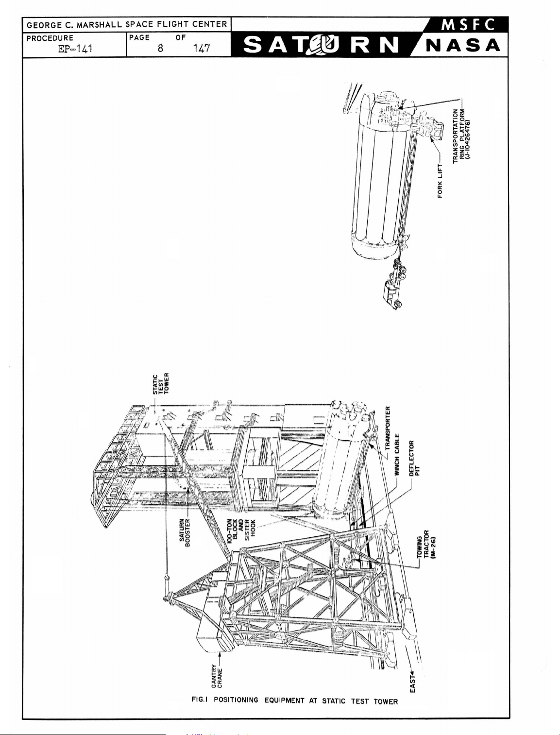
FIG.I POSITIONING EQUIPMENT
AT
STATIC
TEST
TOWER
Page 10
-----
--,--
--
---------------
---
---_._-._----------
...
_-----
[I
--
L
---------
-------
--------
"~?,-.-
1%2'\
----
E§
--
---
7\
-
__
U
PIN
(C-10411722)
(I)
NUT J_
NAS-1022
(I)
~
REQ'O
~
REQ'O I
U
D
~------SCREW
/ 7513-1032 -12A
i
~
~
S>
~
I /
I)
I)
~
I
l1
i ' 1
Q '
~
I I
.r-PLATE
~
(0-10411753)
(~~~~1I723)
~
REQ'O
'1
~
I I
~
I
I)
'-----~-----SCREW
r-~~J-1022-C8
~
,
~
,,1,
.....
~
I-----SCREW
~---OOOR
{f)-~OE4J!621l
(I)
REQ'O
LOCK
PLATE
(C-10411724)
(Il
REQ'O
AN501AC416-8
(I)
REQ
' O
(0-10411708)
7513
-1032-12A
(10)
REQ' 0
-0
DETAIL
A
FIG.2 REMOVING
DOORS
AND PLATES
REF.
OWG
10411701
.
Page 11
GEORGE
PROCEDURE
C.
EP=141
MARSHALL
SPACE
PAGE
10 147
FLIGHT
OF
CENTER
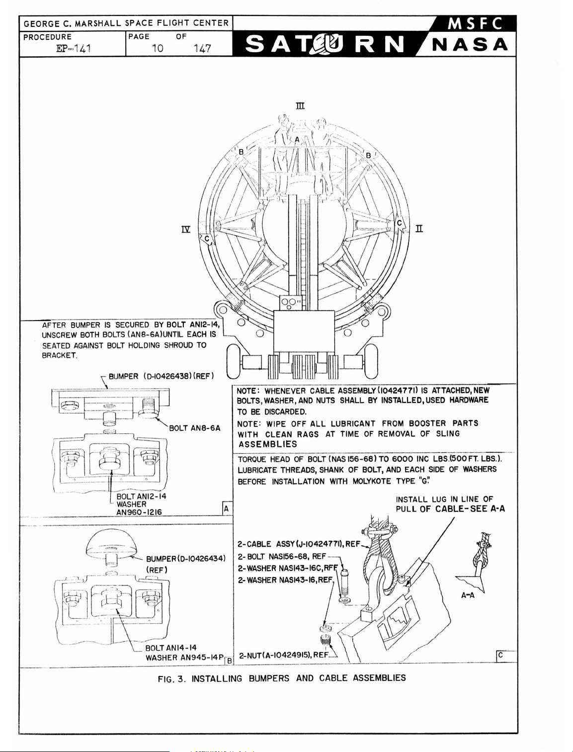
ill
R
BUMPER
UNSCREW
SEATED
BRACKET.
AGAINST
[~
.
~-jJ~ ,-~:~ =-i-~.:-
~~
IS
BOTH
SECURED
BOLTS
BOLT
BUMPER
BY
BOLT
AN12-14,
(AN8-6A)UNTIL
HOLDING
(D~0426438)(REF)
EACH
SHROUD
IS
TO
_-~-=~1r'
---Q--
~
"
BOLT
AN8-6A
TANI2-14
WASHER
NOTE:
WHENEVER
BOLTS,WASHER,AND
TO
BE
DISCARDED
NOTE: WIPE OFF
CLEAN RAGS
WITH
ASSEMBLIES
TOROUE
LUBRICATE
BEFORE
2-
22-WASHER NASI43-16C,RFF.
2-
HEAD
INSTALLATION
CABLE
ASSY
BOLT
NAS156-68,
WASHER
NAS~3-I.'R?
CABLE
.
ALL
OF
BOLT
THREADS,
(J-1042477il,
NUTS
SHANK
REF
AT
(NAS
fi
ASSEMBLY
SHALL
LUBRICANT FROM BOOSTER PARTS
TIME
156-68)
OF
WITH
R
_
~
1042477
BY
INSTALLED,USED
OF
REMOVAL
TO
BOLT,
AND
MOLYKOTE
_
6000
EACH
TYPE
INSTALL
PULL
IS
ATTACHED,NEW
HARDWARE
OF
SLING
INC
LBS(500FT
SIDE
OF
"G'.'
LUG
OF
IN
CABLE-
WASHERS
LINE
. LBS.).
OF
SEE
A-A
BOLT
AN14-14
WASHER
FIG
AN945-14
. 3 .
INSTALLING
2-NUT(A-10424915),
BUMPERS
AND
~
~
R
~
CABLE
ASSEMBLIES
Page 12
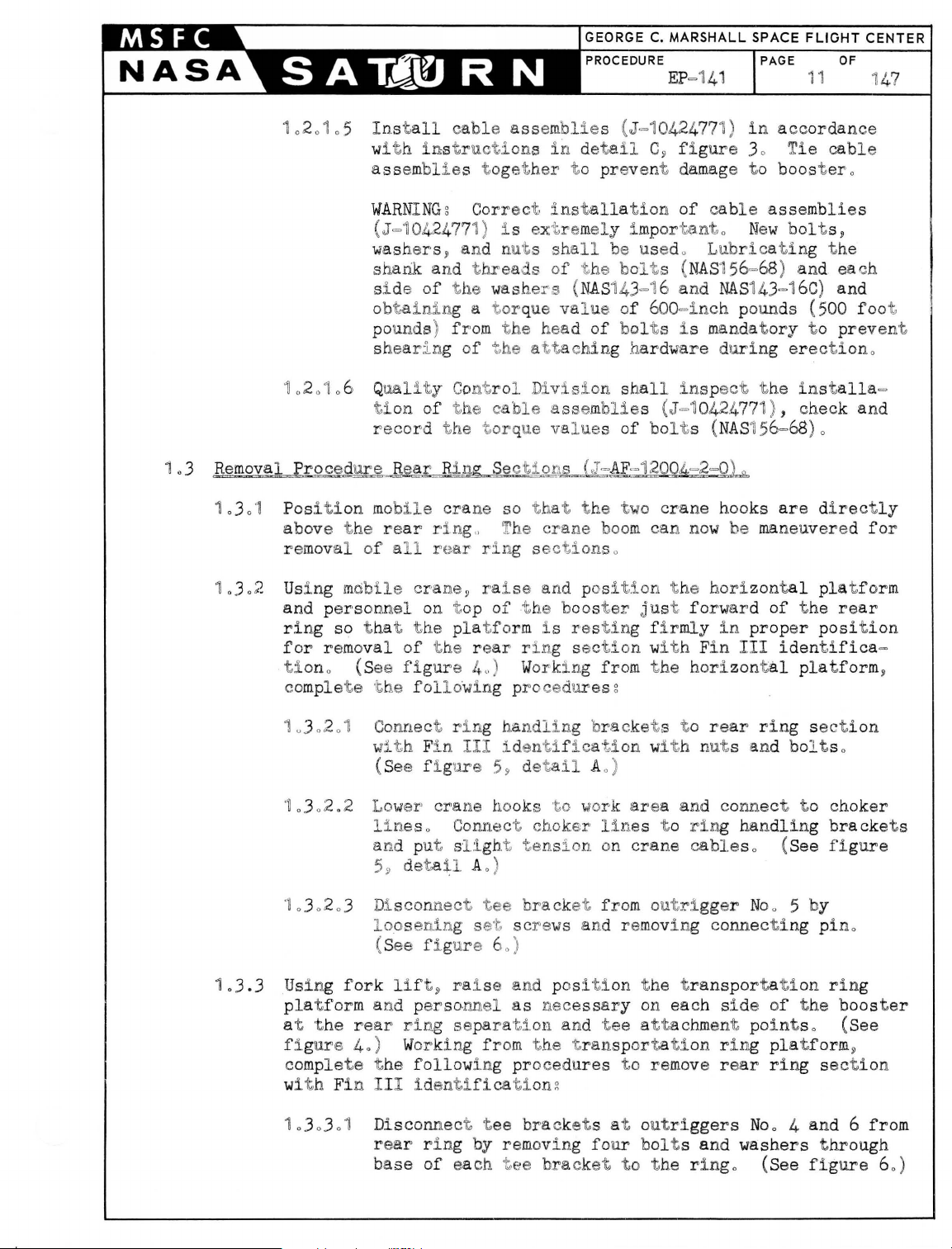
1020105 Install
w
ith instructI
assemblie
cab l e
s toget
assemblie
s (J=10424771)
ons i n deta
her
t o prevent damage to boos
il
C~
f i g
ure
in acc
30 T
ordan
ie
tero
cabl
ce
e
1
1.
03
302
2
1
0
0
01
Posi t i on m
abov e t he r e
mov
r e
Using m
and p
ring so t hat
for
ti
ono (See f i
comple
WARNIN
(J=,10424771) i s ext,remel
washers
shank and
si de
Gg
Cor
~
and nut s sha
thr
of t he
rect
eads
wash
el~
inst
allat
ion
y importa.nto New
ll
be used o
of t he bol t s (
s
(
NAS
143=16 and
of
cab
le
assemblies
Lubricatin
NAS
156=68) and ea eh
NAS14J=16C
obtaining a torque va l ue of 600=inch pounds (500 foot
po
sh
10
6 Q
ti
r e
al
of a 1 r e
obile
er
son
removal
te
t he
unds) f r
earin
uality
on of
cord
obile
ar rin
crane~
nel
the
of
followi ng p
om
the
hea d
g of
the
attac
Control Divisio
the
cab
le assemblies (.T=1
the
tor
que val ues
cra
ne so t hat t he two
g" The
ar
ring section
raise and
on t,op
t he re
gur
pla
e
tf o
4,,
of
t he boos
rm
ar
r i ng sec
) W
i s res
orkin
rocedure
hin
crane
pos
g f
of bol
t s i s
mandatory
g hardware du
n sha
ll insp
ect
0424771 ) , check and
of bolt
boom
crane
can n
s (
NAS156=68
hooks
ow
s o
ition
t he
hori
ter just forward
ting firmly
tio
n with F
rom
t he horizont
in
in
s g
ring
t he installa
are directly
be
maneuvered for
zontal
of
prop
III
identifica
al
bolt
s,
g t he
) and
t o preven't
erectiono
)0
pla
t form
the
rear
er
position
platform
=
=
~
1
.3.3
10
302
'~
.302
10
30203 Di
Using
pla
t f
1 Connect ri ng
0
wi
th
F
in
.2
Lower
1ine
and p
loosenin
fork
orm
and perso
(See f i g
5
~
scon
(S
ee
lift~
ure
crane hook
s o Connect choker
ut sli
deta
il
nect
g s
fi. gur e 6
ra
handling 'bra
III
iden
59
ght
A 0 )
tee
et scre
0)
i se and p
nnel
as
at 'the rear rlng separat,;i
f i g
ure 40) Working from
c
omplete
wi
t h Fi n I II
10303
t he following proce
identif
01
Disconnect t ee
re
ar
ri ng by removing
base
of
each t ee
ica
t iong
t i fica t,
detail
s ,
to
ion wit
A 0 )
work area and conne
line
ten
si on on
bracket fro
ws
and re
osition
nece
ssary
on and
t he t
tee attachment point
ransportation ring
dures
bracket
s at o
four bol
bracket
cket s t o
rear
ring
sec t
h nuts and bolt s 0
ct
to
s t o
ring handling
crane
cable
s o (See figu
m outrigger Noo 5 by
moving conn ecting pino
t he t
ransportati
on each si de of
on
the
s o (See
p
latf orm
to remov
utri
e re
ggers
ar
ring sectio
4
No
o
and 6 from
t s and washers t hrough
to
t he ringo (See f i
ion
choker
brackets
re
ring
booster
~
n
gure 60)
Page 13
GEORGE C. MARSHALL SPACE FLIGHT CENTER
PROCEDURE
EP
=141
PAGE
OF
12 147
::E
0::
o
LL
I-
«
0..
--.l
«
I-
w
z
«
0:
U
W
--.l
Ql
o
::E
--.l
l-
LL
::J
~
0::
o
LL
\
(.!)
Z
0:
0:
«
w
0:
W
I
l-
LL
o
(/)
z
Q
I-
U
W
(/)
o
0:
«
o
Ql
~
:)
o
o
z
«
0:
W
0..
0..
::J
(.!)
Z
>
o
::E
w
0:
I-
0..
0:
o
I-
U
W<!)
~Z
W-
og
00:
I-Ill
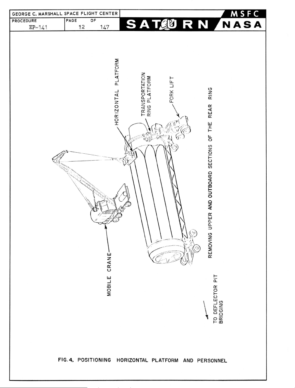
FIG.
4.
POSITIONING
HORIZONTAL PLATFORM
AND
PERSONNEL
Page 14
PROCEDURE
EP=141
FLIGHT
OF
13 147
.
CHOKER
CENTER
LINE
CHOKER
TYPICAL
LINE
\ I
~
;
)""-IJ-AF-12004-2-01
ASSEMBLY
HANDLING
IJ-I04244401
F.:OR
BRACKET
ALL
REAR
RING
RING
RING SECTIONS
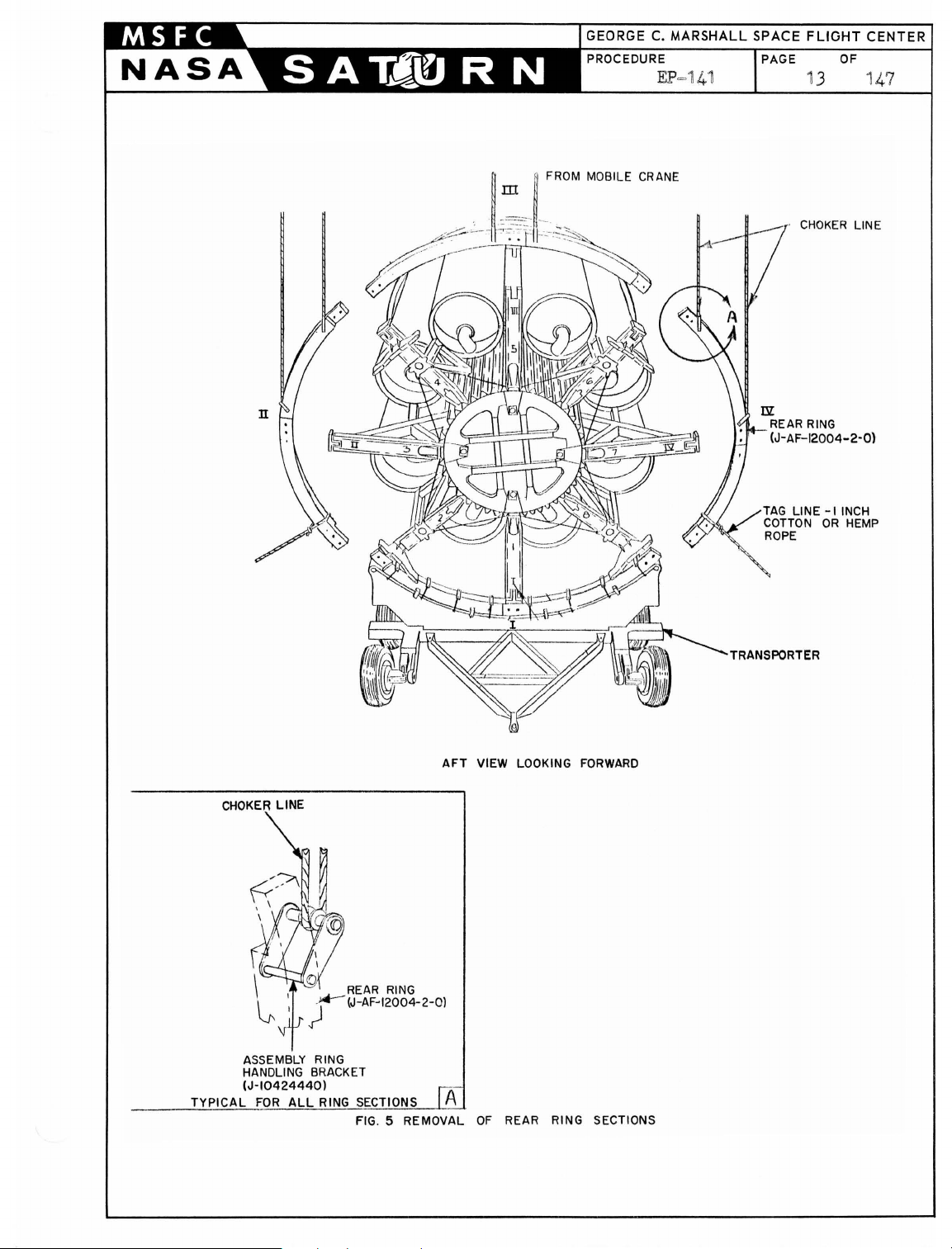
FIG
. 5 REMOVAL
AFT
VIEW LOOKING
OF
TRANSPORTER
FORWARD
REAR RING SECTIONS
Page 15
GEORGE
PROCEDURE
C.
EP
MARSHALL
-141
SPACE FLIGHT CENTER
PAGE
OF
14 147
(J"AF-12004 -2"17)
SCREW
ROTATED
180·
) B(AF-12004-2"3)
,
~
C6~~ECTING
~
~
---
·TEE
BRACKET
D(AF"12004-2"2)
TYPICAL
FIG.6 REAR
DETAIL
AT
OUTRIG
RING
SECTION ATTACHING
A
GERS NO
.2.4.6
POINT
AND
S
8
Page 16
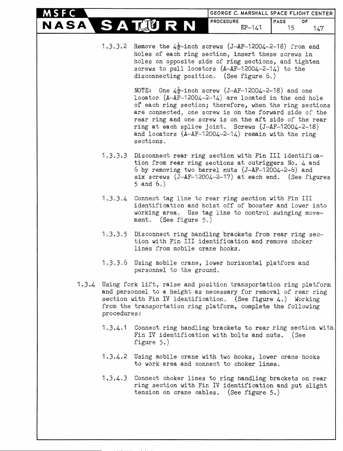
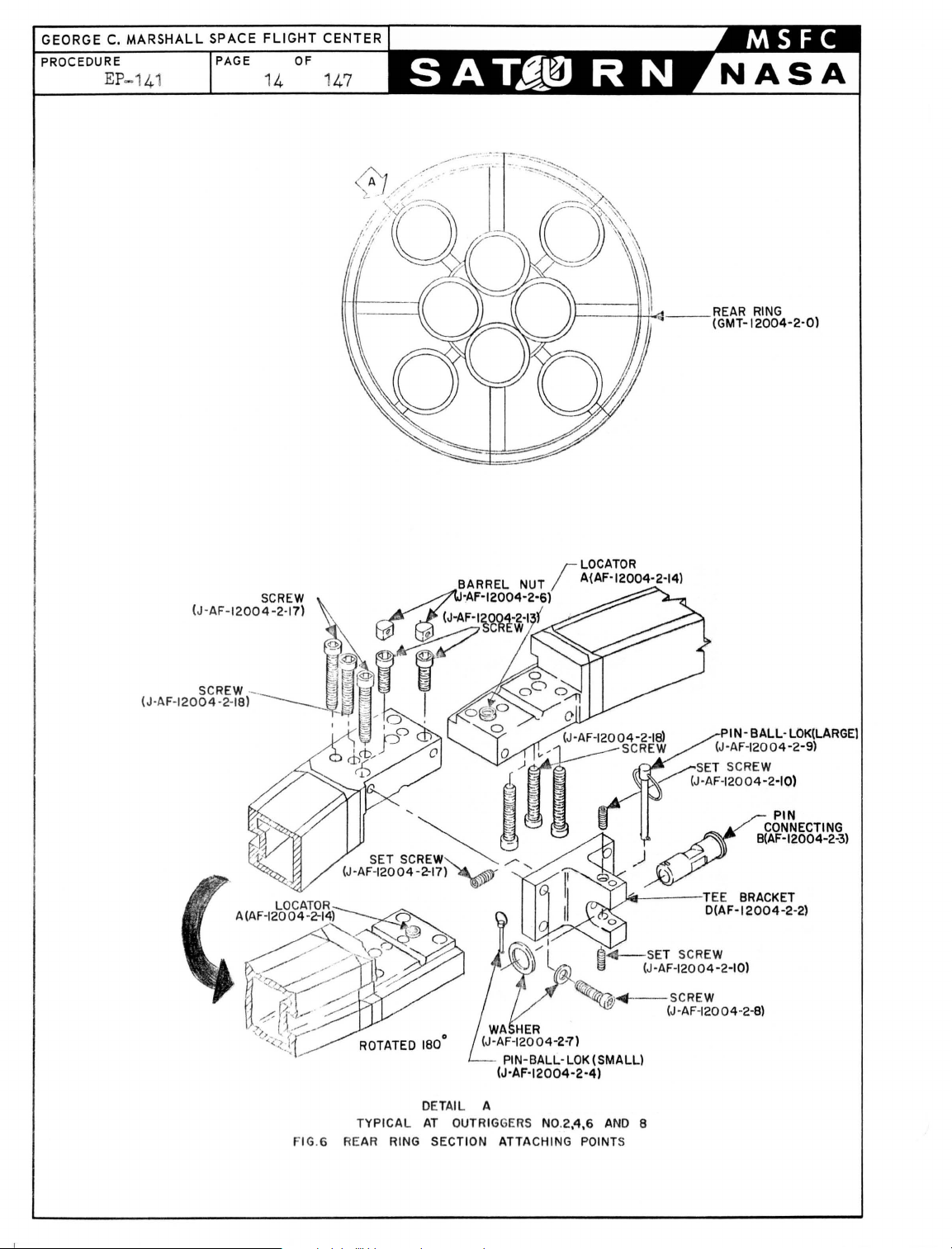
1.303.2
Remove
holes
holes
t he 4!=
of each
on opposi
screws t o
di sco
l ocat
of
are
rear
r i
and
nnectin
NO
TEg
or (A=AF=1
each ring
c
onn
ring
ng
at
locators
One 4!=
ect,ed~
each splic
sections o
inch
scr
ews
ring sectiony inser
te
si de
of
pull locato
g pos
inch
rs
(A=AF=1
iti
ono (See fi g
screw (J=AF=1
2004=2=14)
section; t
herefore,
one screw i s on t he
and one s cr ew i s
e j o
into
(A=AF=1
2004=2=14) rema
(J=AF=
12004=2=18) from
t t
hese
ring sections
2004=2=14) t o t he
ure 60)
2004=2-18) and one
are
loca
t ed
when
forward
on
t he aft
Screws
(J=AF=1200
in wit h t he
screws
in
, and t i ght en
in
t he end
t he
ring
sections
side
side
of
of
t he
4~2~18)
ring
end
hole
t he
rear
1
.3.4
103.3.3 Dis
connect
ti
on from
6 by remov
six
screws (J=AF=1
5 and 60)
1
0303
04
Co
nne.d tag
iden
t ifica
work
ing areao Use tag line
men
t 0 (See f i
10
3.3.5 Disconnect r
ion wit h F
t
lines
10
30306 Using
p
Us
ing
fork
and
personne
section wit h
from t he t
pro
cedur es g
10
3.4
.1
Con
Fin
f i g
from mobile cra
mob
er
sonnel
lif
t , raise
l t o a hei ght
Fin
ranspor
nect
IV
ure
rear
ring sectio
rear rin
in
g t
wo
g s
barrel
2004=2=17) at
line
tio
to
r e
n and hoi st
gure 50
ing handling
in
III
i dent i f
ile
crane, lower
t o
the
gro
und 0
and posi t
as
nece
IV
i d
entification.
tation ring pla
ring
handling
identification
5. )
n with Fi n
ecti
ons at out ri
nut s (J=AF=1
ar ring secti
off
of
t o cont
)
brackets
icatio
ne hooks .
horizon
ion transporta
ssary
for
(See
tform, compl
bracke
with
t s t o r ear
bolts
III
identific
ggers
No
. 4 and
2004=2=6) and
each
boost,er
end. (See
on w
ith Fin III
and lower i nt o
rol
swinging
from
rear
ring
figures
move
sec
n and remove choker
tal
pl at form and
t i
on
ring
removal
figure 4.)
ete
t he
pla
of
rear
Work
following
i ng
ring sectio
and
nut
s.
(See
a-
-
=
tform
ring
n with
1
.3.4.2
1.3.4
Using mobil e
to
work
03
Connect
ri
ng sect i on wit h F
t
ension
area
cho
on
crane wit
and con
ker
l i
crane
h t
wo
nect
nes
t o ring hand
in
IV
hooks,
t o choker
i d
enti
lower
lineso
ling
bracke
fication and put
cables. (See figure 5.)
crane
t s on
hooks
rear
sligh
t
Page 17

GEORGE C.
PROCEDURE
MARSHALL
EP=141
SPACE FLIGHT CENTER
PAGE
1
.3.4.4
OF
16 1
Disconnect
47
outrigger
t
ee.
Remove
at out ri gger No. 8. (See
tee
No.7
two
bracket
from
by removing
bol
t s only from base
rear
ring
four
bolts
figure 6.)
section
from base
of
t ee
bracket
at
of
1
.3.4.5
10
304.6
1.3.
4.7
1.3.4.8
1.3.4.9
NOTEg The
t ee
bra
until
erection
forces
Disconnect
t
ion
by performing
in
paragraphs 1
Connect tag
wi
t h
Fin
Lower personnel and t
fork
lif
hoisting
Wi
t h
personnel
lift rear
of
t he bOOster and lower int o working
crane.
Disconnect
ti
on
and remove choker
remaining t
wo
cket at outrigger
are
cables
obtained
rear
ring
are
from t he t
section
the
.3.3
.2 and 1
line
to
lower end
rv
identification.
ransportation
t and
rear
clear
ring
immediat e
section
positioned
ring
(See
section wit h
figure
ring
handling
5. )
bol
t s t hrough t he base
No
0 8
connect ed and
with
applicable
.3.3.3.
(See
free
t o
maintain a taut tag
Fin
brackets
lines
from mobile crane hooks.
will
remain
ower
and
Fin
procedures
of
rear
figure
ring
area
preparatory
of
booster
IV
identification
from
of
t he
installed
slight lifting
gantry
IV
identifica-
cranes.
outlined
ring
section
5.)
platform wit h
t o
.
line,
free
area with mobile
rear
ring
sec-
1
.3.5
103.4.10 Using
and
fork
lif
personnel
t ee bracket s from out
se
t screws and removing connecting
6. )
1.
3.4.
11
Lower transportati
t he ground with f ork lift.
Using fork lift, raise
form and
ring
Working
following
1.3. 5
1.
3.5
personnel
section wit h
t o a hei ght
Fin
from t he t ranspor t ation ring
.1
procedu
Connect
wi
th
figure
Fin
5.)
res
ring
II
:
.2 Using mobile crane wi
t o work
area
t , rai
t o a
and
II
se transpor
height as
riggers
on ring
position
as
necessary
Noo 6 and 7
pla
tform and pereonnel
transportation
neceSSary
identification.
platform
handling
bracket s t o
identification wit h
th two
hooks, lower crane hooks
and connect choker
tat
ion
(See
rear
bolts
lines.
ring
pins.
pla
and
disconnect
by
(See
tform
loosening
ring
for
removal
figure
4.)
, complet e t he
ring
and
nuts.
(See
section
figure
figure
to
platof
rear
(See
5. )
Page 18

T
CENTER
147
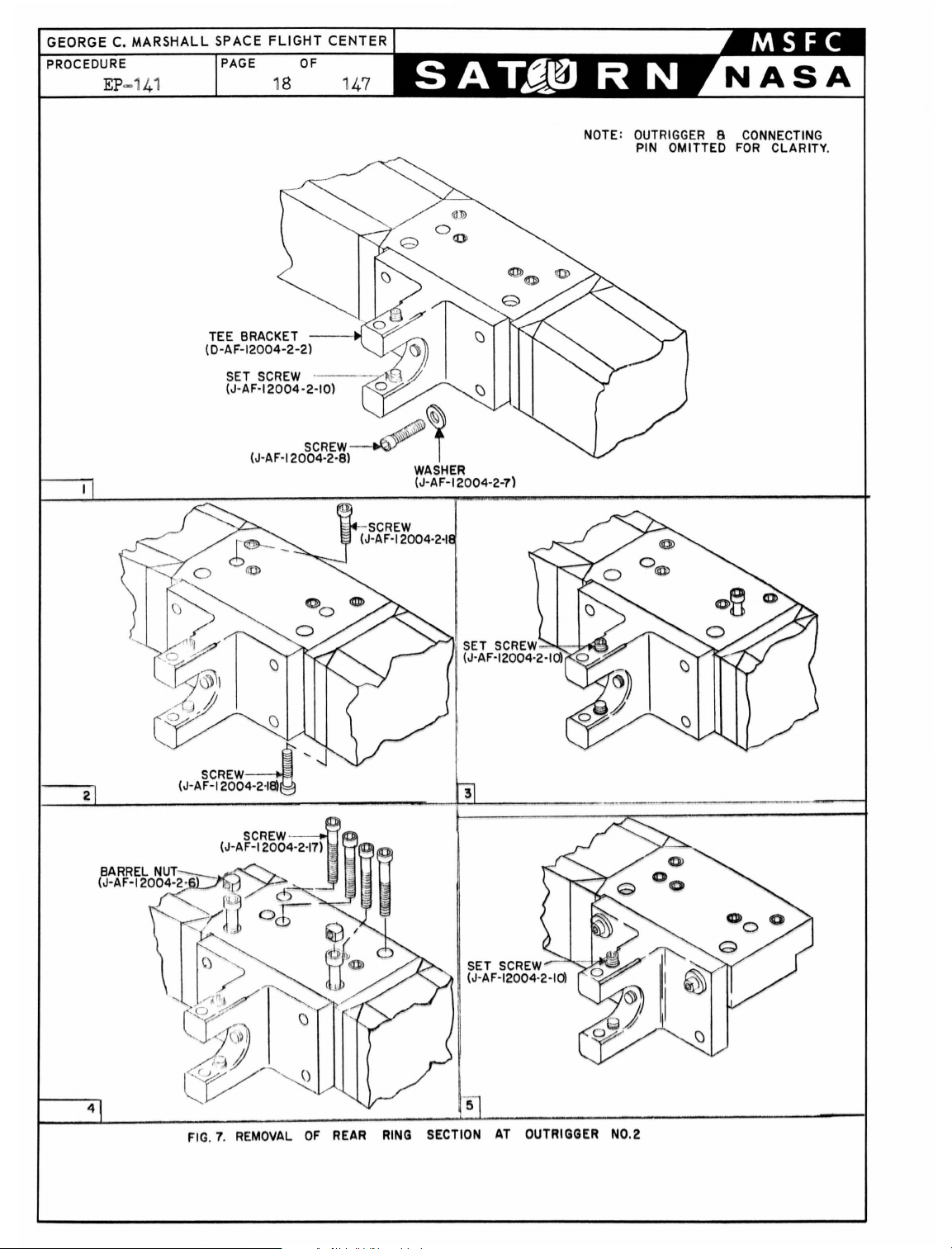
1.3.5.3
1.
3. 5
1.
3.5. 5 Disconnect r ear ring sect
Connect choker lines t o
ring s
ension
t
04
Disconnect t ee
out r i
of
by
ecti
on
on
crane
ggers NOe
each t ee
bra
performing
wi t h F
t he app
in
cables.
brackets
2 and 3 by removing
cke
t.
paragraphs 103.3.2 and 10303.
1.3.5.6
1.
3. 5.7
figure 8 for
numbers
.)
Connect tag l i ne t o lower end
Fin
II
ide
Inser
t t
section wit
and
secure tee
bol
t s . (See
NO
TEg The t
bracke
t at out r i
t he er ection
for
ces
are obtaine
identification
ntifica
wo
barrel nut
h Fi n I
brack
fig
wo bol
cables are connecte
t iono (See
identification at out r i
ur e 6
t s t hrough t he
gger
d from t he t ower and gant
ring handling bra
II identification
(See f i gu
from
rear ring sections at
re 5.)
four
(See f i
gure 6.)
ion wit h Fi n
licable
pro ced
30
of
Fin
of
ure
(See
Li nes and outrigger
rear ring
figure
s (J=AF=12004=2=6)
et
t o
rear ring
0)
base
Noo 2 w
ill
r emai n
d and
cket s on
and put
bol
II
identification
sligh
t s at
s outlined
figure 70)
section wit h
5.
)
in
rear
ring
gger No. 2
section wit h t
of
t he t ee
installed unt
slight
lifting
ry
cranes
rear
t
base
in
(See
wo
il
o
1.
305.8 Lower pe
fork lif t a
hois
t i ng
10
30509
Wi
t h pe
lift rear ring sec
of boos t
crane
1.
3. 5010 Disconnect
t
ion
10
3050
11
Using
pe
rso
bracke
screws
1.
305.12
Low
er pe
wi
t h
ransporter ont o t he
t
NO
TEg The aft end
hree
t
ring
No
o 2 and 8 at out
are sti
wo
of
t
sections stHl
rsonn
el and trans
nd cle
rear
rso
nne l positioned t o maintain
ar
ring sec
t i on with Fin
er
and lower i nt o worki
imme
t i
portat
dia
t e
on
free
ion
ring
area
preparatory
of
boos tero
II
i d
ng
area wit h mobile
0 (See figur e 50)
ring handling bracket
s from
and remove choker lines from mobi
fork
lif
t~
raise t
nnel
t o a hei ght
t s from out ri ggers
and r e
fork
points
moving conn
rsonnel
l i ft and
~
and t
t ee
brackets Noo
section with Fin I identifica
riggers
ll
connect ed t o t
t he four bolt
install
ransportati
as
necessary
Noo 3 and 4 by
ectin
g pins o (See
ransportation ring
clear
the
area
deflector pit
of
t he boost
er
1,
No
o 2 and 8,
heir
out
rigg
s t hrough t
ed o Tee
heir
bracket Noo 1
on r i
and di sconnect t
preparatory
bridgingo
is
2 and 8
t i on o Tee
er beams and have
base
pla
t form wit h
t o
a taut t ag l i
enti
fication
rear
l e
crane
ng
ring sec
hooks
pla
tform
loosening set
figure 60)
pla
t form
to
now
resting
of
t he
bracke
respe
ctively
t o t he ri
is
ne,
free
·=
and
ee
moving
on
rear
t s
y
ng
inta
o
ct
Page 19
GEORGE
PROCEDURE
C.
EP
MARSHALL
~141
SPACE FLIGHT CENTER
PAGE OF
18 1
47
TEE BRACKET
(D-AF-12004-2-2)
(J-AF-12004-2-8)
SCREW
-~
,
WASHER
(J-AF-12004-2-7)
NOTE: OUTRIGGER 8 CONNECTING
PIN OMITTED
FOR
CLARITY
.
SET
SCREW...::...J
(J-AF-12004-2-10l
l-
lrl1!
~
FIG. 7. REMOVAL
OF
REAR
RING
SECTION
AT
OUTRIGGER NO.2
Page 20
U>
b
z
a:
w
<.!)
<.!)
r--.
b
z
a:
w
<.!)
<.!)
a:
I-
::>
0
CD
b
z
a:
w
<.!)
<.!)
PAGE
OF
19 147
10
b
z
a:
w
<.!)
<.!)
a:
I-
::>
0
~S
<.!)
z
0:
z
0
i=
~
a:
0
0..
en
z
<I:
a:
Il-
LL
<I:
~
b
z
a:
w
<.!)
<.!)
a:
I-
::>
0
f()
b
Z
a:
W
<.!)
<.!)
a:
I-
::>
0
b
z
a:
w
<.!)
<.!)
a:
l-
::>
0
b
z
~H
LL
0
a:
<t
~
a:
0
LL
<.!)
Z
:lI::
0
0
...J
~
W
:;:
l-
LL
<t
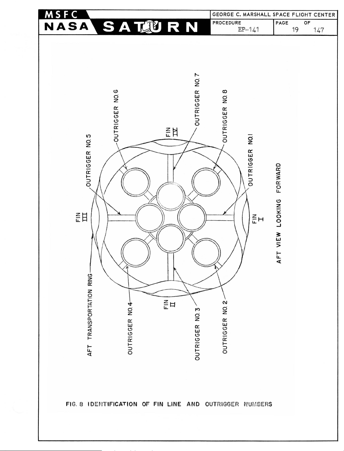
FI
G.
8 I
DE
NTIFICATION
OF
FIN LINE AND
OUT
RiGGER
NUMBERS
Page 21
GEORGE C.
PROCEDURE
MARSHALL
EP
=141
SPACE FLIGHT CENTER
PAGE 2 OF 1
0
47
20
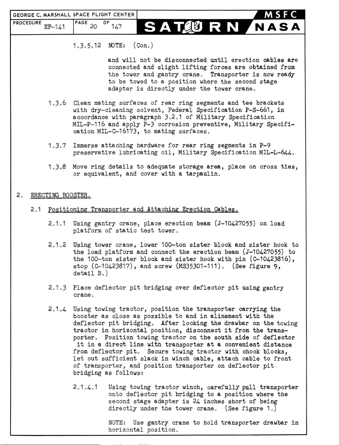
10306
10307
10
308
ERECTING
2
01
Pos
2
0101
and wil l not be
connec t ed and
th
e t
ower
and gant
t o be t
adap t
Clean mating
wi
t h
dry~cleaning
owed
er
is directl
surfaces
solven
accordance wit h paragraph 302
MIL-P=11
cation
Immerse attaching
preserv
Move ring
or
BOOSTER
iti
oning T
Using gant
pla
6 and
MIL
-C=1
ati
ve
details
equivalen
o
ransporter
ry
t form
of
apply
6173, t o mat
hardware
lubricating oil ,
t o adequat e st orage
t , and cover w
and A
crane
static
~
t es t t
disconnected unt
slight
t o a
lifting
ry
crane 0
position
y under t he t
of
P-3
rear
t~
corrosion
ring
Federal
01
ing
surfaces
for
of
rear
Military
ith
a t
arpaulin
tta
ching Erect
place erection
ower
o
il
erection
forces
are
Transporter
where t he second
ower
crane
cables
obtained
is
now
stage
o
segment s and tee bracke t s
Specification
Military
prevent
ive,
p-s=66
1,
Specification
Military
Specifi-
o
ring
segment s
Specification
area,
place
in
P-9
MIL-L
on
cross ties,
0
ion
beam
Cab1es
(J~10427055)
g
on
load
are
from
ready
in
=6440
10
2 Using t
2
0
t he l oad
t he 100=t
st
de
20103 Place
cra
2
0104 Using t owing t
boost
ower
pla
on
op
(C=10423817) , and screw
tail
Bo)
defl
ne
o
er
as
deflector pit
t
ractor
portero
it
from
l
et out
in
Position towing tractor
i n a dl
def
lect
sufficient slack
of transporter , and pos
bridging
as
crane,
t form and connect
sister
lower 1
00=ton
block and
sister
the
sister
(MS3530
ect
or pit
ractor,
close
bridgingo After
horizontal
bridging
as
poss
over
position
ibl
e t o and
pos
ition
t he t
locking
, disconnect
on
rect line with transporter
or pito Secure towi
in
ng tractor with chock
winch
ition transporter
follows
Using t owing
onto deflect
second
d
irectly under t
g
stage
t
ractor
or pit
bridging
adapter i s
he tower
winch,
block
erection
hook wit h
1=11
1) 0 (See
deflector pit
ransporter
in
alinement wit h t he
the
t he south
at a
and
sister
beam
(J=10427055)
pin (C=1
figure
using
carrying
drawbar
it
from
side
on
the
of
convenient
0423816),
gant
t he towi
deflector
dis
blocks,
cable, attach
on
carefully
t o a
24 inches
cable
deflector pit
pull transporter
position
short of
where t he
being
t o
crane 0 (See fi gure 10)
hook t o
9,
ry
t he
trans-
t ance.
fron
to
ng
t
NO
TEg
hori zon
Use
tal
gant
ry
crane t o hold t
position.
ransporter
drawbar
in
Page 22

= _ '
_0
r~
O
__
y-
~
A / ' '
~
--£
~'I .-=~"
"
~
r
-
o-"
~
4-
~
"-
"
TON
100
SISTER
HOOK
BLOCK
ERECTION
BEAM
(J-10427055)
"-
f11
- -
' -
BUMBER ASSY (0-
2-BUMPER
~~~~
]
!
~
I
I
10426438)
(0-10426434)
PIN (C-10424412)
~424
:
~)
PAGE
21 147
1\~,\
A
/-
GANTRY
\
).1
BLOCK
https://manualmachine.com/-
AFT
r ASSEMBLY
Il
(0-10423292)
111
(
CONNECTING
{/'
(~~~424657)
1
i~
A
__ 1
~
OF
CRANE
ASS'Y
CABLE
f---------
CONNECTING
TYPICAL
__
NOTE:
BUMPER
NEVER
HAS SOME VISABLE
"-----
------
-----
_____
ERECTION
~
~
·
PIN
----~
FORWARD
TWO
__
.. ______________
ASSEMBLY
BE
LESS THAN
~:
CABLE ASSEMBLY
(J-10424
PLACES
10426438
SPACE
(J-10427055)
~~
ERECTING
771)
IS
90°
FROM
BETWEEN IT
--
2-CABLE
ASSY
(J-10424771
~1
_
~
~
-
-----
f~-
---.---
BEAM
COTTER PIN
--
:::~
J
-
I
_
__________
NOT
DESIGNED
THE
HORIZONTAL CENTERLINE
---
AND
------
FIG.9 ERECTION BEAM INSTALLATION
...
J
~
__
TO
RESIST
EXCESSIVE LOADS,
THE
BUMPER ASSEMBLY_ C
--------"
._.-
--
L--::::::
\
~
[
OF
THE
--
-
---------------
-----.
BOOSTER
,
TOWER
CRANE CABLES SHALL
SO
THAT THE SISTER
8
HOOK
Page 23
GEORGE
PROCEDURE
C.
MARSHALL SPACE FLIGHT CENTER
EP
=141
PAGE
22
OF
"1
47
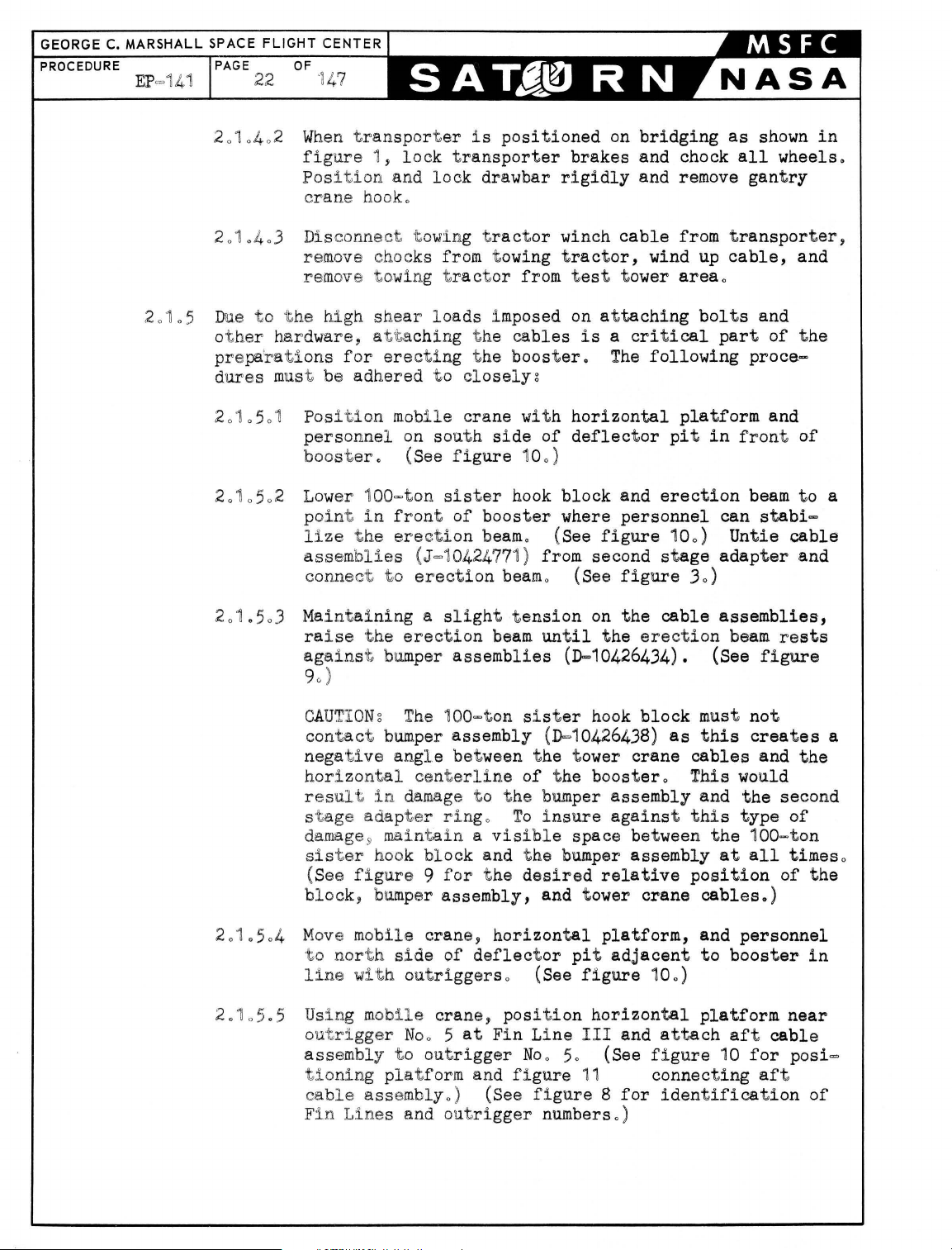
20105
2010402 When tran
fig
ure
1,
Position
c
ran
e hook.
2010403
Disconnect t owing
remove chocks from t owing
remove towi
Due to
ot
prepa'rations
dures
2
0"10501
her
the
high
hardwar
mus
t be
Pos
shear
e, at'ta
for
adhered
ition mobi
personnel
booster.
2
010502 Lower
100=ton
point in
l
:l.ze the
201.5
03
assemb
conne
Mai
ra
lies
ct
ntai
ning a slight
ise the
against bum
90 )
sporter i s
lock
and
lock
tran
drawbar
positioned
sporter
tract
ng t
ractor
l oads imposed
chi
ng
the
erecting the
to
closelyz
l e
crane
on south
(See
side
figure 100
sister
front of
booster
erection beamo
(J=1
0424771 ) from second
to
erection
erection
per
beam
assemblies
or
from t
cables
booster.
with
of
)
hook
(See
beam
o (See
tension
until
on
bridging
brakes
rigidly
winch
and chock
and remove
cable
tractor,
est
tower
on
attaching
is a critical
The
horizontal
deflector
block
where
and
personnel
figure
wind
following
pit
erection
100)
stage
as
from
area
transporter,
up
cable,
o
bolts
part
platform
in
can
Untie
adapter
figure 30)
on
the
the
cable
erection
assemblies,
beam
(D-10426434). (See
shown
all
wheels.
gantry
and
and
of
the
proce-
and
front of
beam
to
stabi=
cable
and
rests
figure
in
a
2
0'10
2.105
CA
UTIO
Ng
The
contact bum
per
negative ang l e between
horizontal
res
ul t in
centerl
damage
stage adapter
darnage9 maintain a visi
sister
(See f i
hook
gure 9 for
block, bumper
504
Mov
e mobile
t o nor t h
side
line with outriggerso
.5
Using m
o
utrigger Noo 5
assembly
tioning
ca
F
in
ble
Line
obUe
to
pla
tform and
assemblyo
s and out
100=ton si
ster
hook
assembly (D-10426438)
the
t ower
ine
of the boostero This would
t o
the
bumper assembly and
ringo
block
assembly,
crane,
of
crane,
at
outrigger
) (See
To
insure
ble
space between
and t he bumper assembly
t he
desired
and tower
horizontal
deflector
position
Fin
pit adjacent
(See
figure
horizontal
Line
III
Noo 50
figure
11
figure 8 for
rigger
numberso )
block
crane
as
cables
must
this
not
creates
the
against this type
the 100
at
all
relative
platform,
crane
position
cables.)
and
personnel
to
booster
100)
platform
and
(See
attach
figure
aft
10
for
connecting
identification
and
second
of
=to
times
of
near
cable
aft
a
the
n
o
the
in
posi=
of
Page 24
STATIC
TEST
TOWER
PROCEDURE
EP-141
PAGE
23
STATIC
TEST
TOWER
FT
ASSEMBLY
OF
CABLE
147
TOWING TRACTOR
(M-
26)
DEFLECTOR
PIT BRI DGING
TRANSPORTER
DEFLECTOR
HORIZONTAL
PLATFORM
MOBILE
HORIZONTAL
PLATFORM
SATURN
BOOSTER
TRANSPORTER
DEFLECTOR
PIT BRIDGING
CRANE
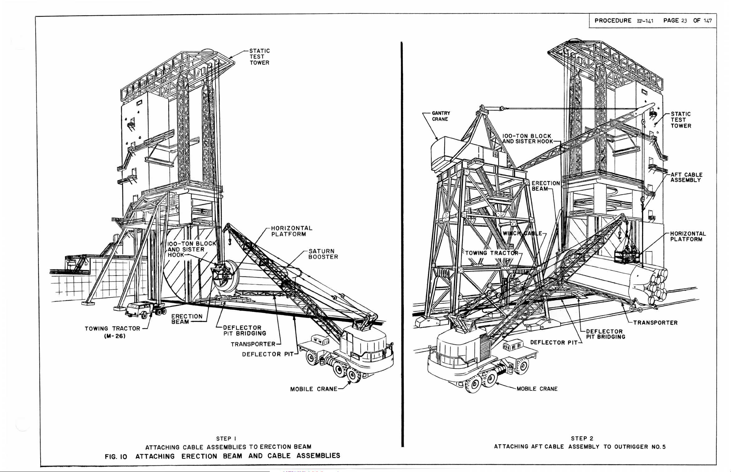
FIG.
STEP I
ATTACHING
10
ATTACHING ERECTION BEAM AND CABLE ASSEMBLIES
CABLE
ASSEMBLIES
TO
ERECTION
BEAM
ATTACHING
AFT
CABLE ASSEMBLY
STEP
2
TO
OUTRIGGER
NO.5
Page 25
~
GANTRY
BLOCK
CRANE
ASSEMBLY
- - - -
---
-
---
CONNECTING
---
PIN~
~
--------AFT
.
~
...
-----
CABLE
ASSEMBLY
(0-10423292)
COTTER
PIN
CONNECTING
(0-10424657)
NUT
OUTRIGGER-------.y-
LINK
(DOG
BONE)
~
.
~
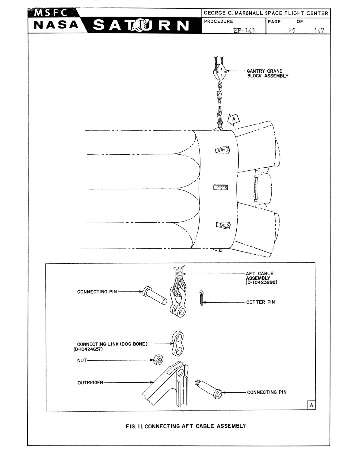
FIG. II. CONNECTING
@;
AFT
~
CABLE ASSEMBLY
CONNECTING
PIN
A
Page 26
PROCEDURE
EP-141
PAGE
26 147
OF
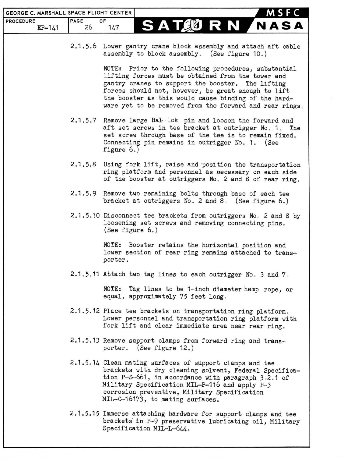
201.5
2.1.5
2
.1.
508 Using
2.105
2.1.50
.6 Lower gan t
assembly
NOTE:
lifting
ry
gant
forces
t he boos t
ry
t o
Prior
forces
cranes
should not,
er
ware yet t o be r e
07
Remove
aft se
set
Connecting
figure
ring
of
.9
Remove two
bracke
large
t screws
screw t hrough
pin
60
)
fork
pla
lif
t form and
t he boos t
rema
t at out ri
10 Disconnect t ee
loosening
(See
figure
set
crane
block
to
as
Bal~lok
er
block
assembly
assembly. (See f
t he
following
must be
obtained
t o support t he
however, be
t hi s would
moved
in
t ee
base
remains
t ,
raise
cause
from t he
pin
and
bracke
of
t he t ee
in
out
and
position
personnel
at outriggers
ini
ng bol
ggers
brackets
t s t
No
2 and 8.,
o
from outriggers
and at
igure 100)
proceduresy substantial
from t he tower and
booster
great
.
enough t o
binding
forward
loosen
t at out
rigg
t he
rigger
is
t o remain
er Noo
t he transportation
as
necessary
No.2
hro
ugh b
and 8
ase
(See f
screws and removing connecting
60
)
tach aft
The
lifting
of
t he
and
rear
forward
No.1.
10
(See
on
each
of
rear
of
each tee
igure 60)
No
2 and 8 by
o
lif
hard-
fixed
pins.
cable
t
rings
and
The
.
side
ring
o
.
NOTE:
lower
porter.
2.1
05.11 At
tach two
NOTE~
equal,
201.5.12
Place
Lower
201.5.
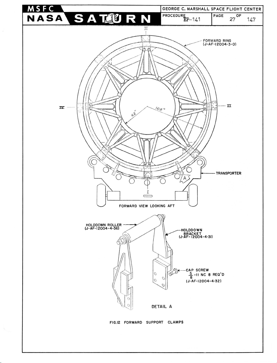
13
fork
Remove
lif
porter
2.1.5.14
Clean mat
brackets wit h
tion
p=s=661,
Military
corrosion
MIL=C=
01.5.1 5 Immerse at
2
bracke
Specification
Boost
section
approximately
tee
personnel
er retai
tag
Tag
lines
bracke
t and cle
of
rear
lines
t o be
t s on t
and t
ar
ns
ring
t o
75
ransportati
immediat e
support clamps from
. (See
ing
figure
surfaces
dry
cleaning
in
accordance
12
of
Specification
preventive,
161
73,
taching
t s'
in
t o mati
P-9
preservative
MIL
Military
ng
hardware
=L=644.
the
horizontal
remains attached
each
outrigger
1=i
nch diamet
feet
long
o
ransportation
on
area
forward
0)
support
clamps and
solvent,
with
paragraph
MIL
=P-116 and
Specification
surfaces
for
0
support
lubricating
position
Noo 3 and 70
er
hemp
ring
ring
near
ring
pla
rear
and
Federal
apply
clamps and
oil,
and
t o t
rans=
pla
rope,
tformo
or
tform wit h
ring
o
trans=
tee
Specifica=
3.2.1
of
P=3
tee
Military
Page 27
GEORGE C.
_-
________ . (J-AF-12004-3-0)
FORWARD
RING
HOLDDOWN
(J-AF-12004
FORWARD
ROLLER -
- 4-36)
--1
V
=
VIEW
LOOKING
DETAIL A
AFT
-HOLOOOWN
BRACKET
(J-AF-12004-4-31l
Y/~
CAP
~
(J-
1----
SCREW
i-II
NC 8 REa'o
8
AF-12004-4-32)
TRANSPORTER
FIG.12
FORWARD
SUPPORT CLAMPS
Page 28

GEORGE C. MARS
PROCEDURE
202
Removing Boost
L SPACE
PAGE
201
0
FLIGHT
28
5016
er
CENTER
OF
147
Move
storage
c
ov
from
support clamps and t ee
area,
er
with a tarpaulin
Transporter
place
and
on
Positioning
bra
cross ties,
0
cket s t o adequat e
or equivalent, and
on
Tow
er Th
rus
t Ringo
2.201
Have
ment of
figure
bar
20
20102
2020103 Using t
202
02 With tower
booster
ring
20203
Using towing
Clean and
ou
tl
men
hold
boost
13
0)
Using t ower
lifting
above t he
rear
Gonne:c
using tow
the
free
This st.
of
crane
off transporter
section
o
preserve transporter
ined
in
paragraphs
each
er
as
of
it
force
bottom set scr ew
out
rigger
t towing t
bar
rac
t orjl
connecting
In t he
l9.b.ilizes
transporter
and
gantry cra
(See
figure
tractor,
t he
four
is
raised
cra
ne and gant
t o
tag
from t he
raise boo
lin
ry
ster
es
to
transporter o (See
crane~
approximately t=inc
located
No
10
o
ractor
0
(See f i
t o t he aft end
move transporter
pin
in
out
slot of
t ee
booster
prepara
bracket
rigger
gur
es 13 and 140)
f orward
No
at out
t ory t o liftin
o tSee f i gur es 13 and 14
ne lif t i ng
to
a hei gh't that wi
sim
ll cle
130)
remove tran
10205
sporter f rom
us i ng app
and
10
2060
licab
prevent undue move=
appl y a
slig
ht
h
in tee
bra
of
t ransporter
cket
at
or aft unt i l
0 1 i s
floating
rigger Noo
10
g clear
0)
ultane ous
ar
stat
le specifi ca
ly~
hoist
t he r e
ar
i c test ar ea
tion
s
o
20204
Wi
t h
the
booster still
t
ransportery remove
out
rigger
No
20205 Using tower
202.6
202,.7
20
2.8
gantry
maneuver
Using mobile
outrigger,
at
No
Lower
'
crane
Using tower
main
vertically
lines
position
Fin
if
5
o
horizontal
and
load
to
crane
0 (S
Line
conditions
horizontal
platform,
personnel
i t a few
in
horizont,a
pin
in
out
rigger
0 1
if
crane
t o
ee
crane
cond! t
~
hois
sta
bi lize booster and take up sl ack
figure
and hori zontal pl at form t o gai n
ions
t boost
150)
warra
er into
disconnect aft cable ass
1110 (See f i
gure
150) A
warranto
pl at form
pla
craney hoist booster
move
over
opening
on main
fee
t above t
using mobile c
tform from stat i c test H
t o a he
boost
of
er hori zon
main
load
load
pla
hrus
l
posi
t.i
on~
but free
No
10
At
o
nt
0 (See f i g
vertical positi
tach tag line t o
ure
14
0)
ono
duri
access
embly from outrigg
er Noo 5
ttach tag line t o outr i gg
ran
e'. Re
ight suffici
tall
pla
tform, transfer tag
t form; lower boost
move mobile
rea
o
ent
y t o a posiUon
er
t ringo (See f i gur e
of t,he
Use
ng
t o
to cle
and
150
)
er
ar
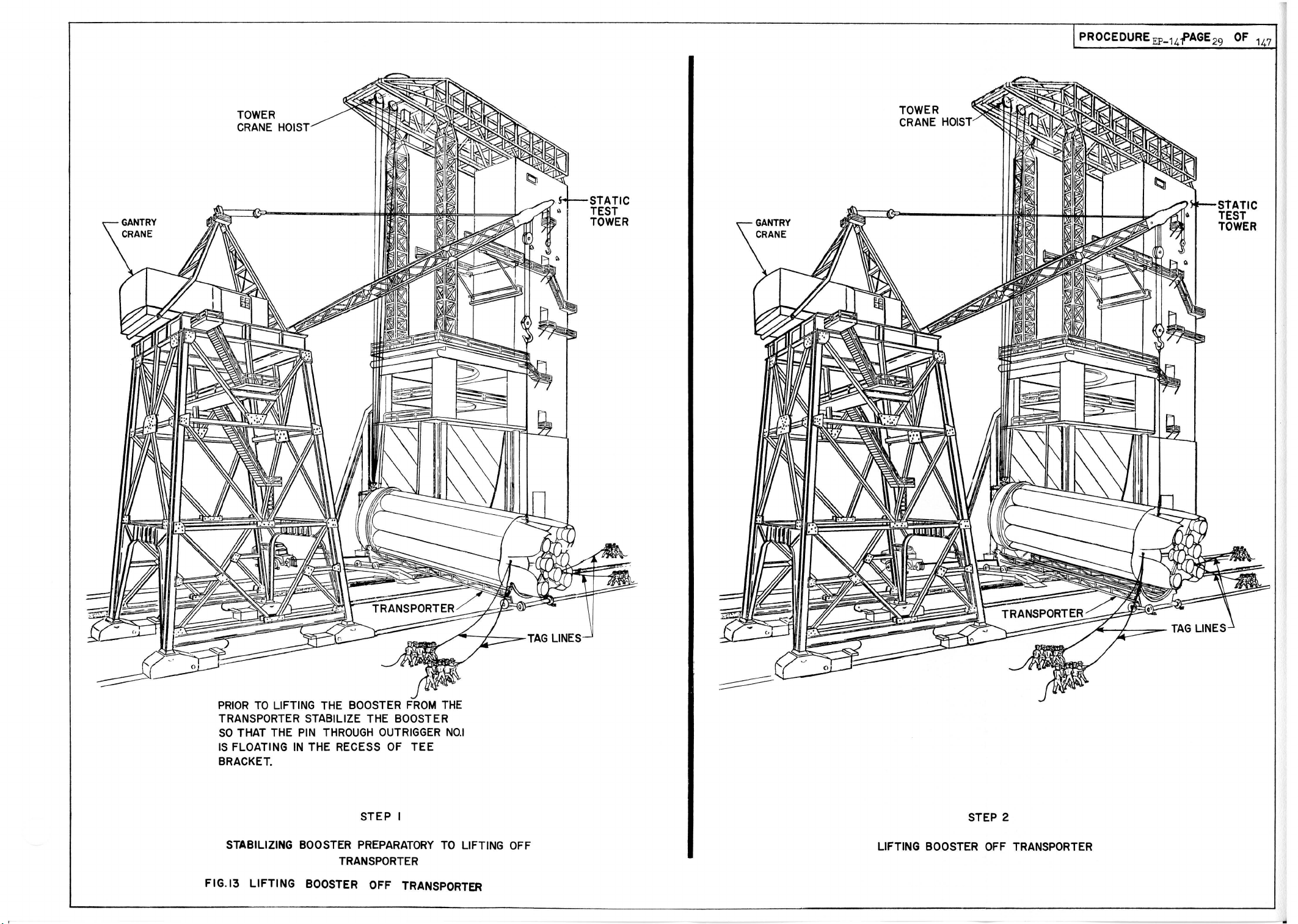
Page 29
TOWER
CRANE
HOIST
PROCEDURE
EP-14f
AGE
29
OF
stATIC
TEST
TOWER
147
PRIOR
TO
LIFTING THE BOOSTER
FROM
TRANSPORTER STABILIZE THE BOOSTER
SO
THAT THE
IS
FLOATING
PIN
THROUGH
IN
THE RECESS
OUTRIGGER
OF
TEE
BRACKET.
STABILIZING BOOSTER
STEP
PREPARATORY
I
TRANSPORTER
FIG.13
LIFTING
BOOSTER OFF TRANSPORTER
THE
NO.1
TO
LIFTING OFF
STEP 2
LIFTING BOOSTER
OFF
TRANSPORTER
Page 30

OUTFllGCiER
[\10.
1
PIN CONNEC
(B-AF-12004-2-3)
FIG.14. BOOSTER
TING
STABILIZATION
PREPARATORY
TO
LIFTING
OFF
TRANSPORTER
Page 31

PROCEDURE
PAGE
OF
Page 32

GANTRY
CRANE
TOWER
CRANE HOIST -
IOO-TON BLOCK
AND
SISTER HOOK
ERECTION
BEAM
AFT
CABLE
ASSEMBLY -
NO
.5 OUTRIGGER
--------1+-f---+!I
.......,.
....
~~~~~~
~
~~
PROCEDURE
OUTRIGGER
TEST
TOWER
PIN
~
ASHE
~<9
~
~\
~
~
NUT
A TYPICAL 8 PLACES
~
TIEROD
EP_1~GE
33
OF
SUPPORT
BRACKET
NUl)
WASHE~~
D
147
DETACHING
STEP I
AFT
OUTRIGGER
CABLE ASSEMBLY FROM
NO
.5
MOBILE
CRANE
o
STEP 2
POSITIONING BOOSTER
ON
TEST
TOWER
FIG.
15
BOOSTER
IN
VERTICAL
P{)SITION
Page 33

CENTER
20209 Us
tower
2020
'W
Remove tag
on
outrig
202
011
Inser t t est t ower pins (
accordance wit h inst ructions from M
202012 Us
'tower
202.13
202
Remove ga
014
Disconnect cable
adapt
cl e
CAUTION
blies t o prevent
202
015
The removal of bumper
(D=10426434)
I=>beams No
insi~ructions
(See fi gur es 3 a
in
g tag
t o t,h
in
g gant
er 0 Ra
ar
lines
support
rus
t ringy usi
gers
ry
area
0
~
brac
lin
es
int
o suppor t
crane,
aline
ket s
and lower booster through main
ntry crane
assem
i se
erection
of
boost
er
and lower t o t he groundo (See
g Care must be
damage
an
d t he
0 3
~
4)
5)
as
out
nd
boost er out r i
o
ng p
bracke
figure
remove
(See f i
ersonnel
defl
gure
t s o (See
16)
ect
or pit
from test t ower
blie
s (
J=1
0424771) from
beam
with
exer
ci sed
in
t o t he second
assembly
installation
(D=1042643
of
6 ~ and 7 1s essenti
line
d i n
paragraphs
4
0)
ggers wit h
15
0)
t o s
tea
dy
booster
figure
in
support
=TEST
LAB
o
bridging
area
o
cable
assemblies atta
disconnecting
stage
adapter o
8) and bumpers
original
ally
1020101
respective
load
pla
and
)
16
0
bracke
t s
from test
se
cond
stage
figure
cable
hardware at
t he
reverse
thr
ough 1
tes
tform
guide
in
ohed
3
0)
asseffi=
of
2
1
0
0
0
t
40
30
202016 C
REl10VI NG
.3
0 1
Pr
epar i
30
101
3
010
3
0103
3
0104
0105
3
le
ar
t,est t ower
BOOSTER
FROM
ng BOQ,ster
Pla ce
deflect
crane 0
< U
sing
t owing t
possi bl e t o and
A
ttac
h gant
horizo
ntal
Di sconnec t t
so
uth
si de of
and i n
lin
Attach wi nch
pos
,ition on t he
When transport
as shown
wh
eel
so
area
TEST TOWER
for
Rem
or pit
ractor
in alinemen
ry cra
ne t o drawbar and support t he drawbar
positio
ractor
the
e
with
the transporter 0 (See fig
to tra
defl
er
i s posi t i oned on
in
f igure
,
o
ovaL
bridging ov
, p
osi
t i on t he t
t with t he
no
from t ransport
def
lector pit
nsport
er
draw
ect or pi t b
1j
l ock tran
er deflect
ransporter
deflector pit
er
and move t he t
with
bar
ridgin
the tractor
and winch t
go (See
deflector
sporter
brakes
or pit
as clo
ure
1
ransporter int o
figure
pi t br idgin
and chock
using
bridging
ractor
wi nch
0)
gant
se
in
facing
10
)
g
ry
as
o
a
t o t he
all
Page 34

GEORGE C. MARSHALL SPACE FLIGHT CENTER
PROCEDURE
EP~141
PAGE
36
OF
1
47
NOTE:
SHROUD
NOT
SHOWN
A TYPICAL 8 PLACES
FOR
CLARITY
FIG. IS-POSITIONING BOOSTER
OUTRIGGER
------~--.-
ON
-
SUPPOR
T BRACKET
.---~--
.
..
--
- ----.
Page 35

MARSHALL
SPACE FLiOH
PAGE
37
OF
1
47
301.6 Lock
Move tractor
of t
30
107
010
3
30'09
.3
0 10 '
Uslng tower cra
wi
t h
to
a position
8 R
emove doors
4
~
5,
Install
A
~
fi gure
10
Ins
tall
f i gur e 30
30'
;11
Low
a
nd
washers,
f i gure 30
WARNING
i s ext remely impor
'U
sedo Lu
and each si de of t he
obtaining
from
a
tta
and posi t i oning
dra~bar
in
t o nor'th
ransporter o
erection
and
6
~
a
nd 7 as outlined in
bumper assem
.3
0
bumpers (0=,1042
er er
ection beam with
i ns
tall cable
and
nuts
g Corr
bricating the
a torq
th
e head
chme
nt
hardware
rigid
ne, low
beam
pos
iti
on
side
of test t ower and at
er 100=ton si st
and
cable
assemblies
and disconnect gant
tach
er block and
(J=1
0424771)
directly above t he second st age adapt
necessary fli
ght hardware at out
riggers
paragraphs1020L1 and 10201.20
bly
ect
of
(D=104
6434)
assem
blies (J=1042477
in
accordance wit h
ins
tal
lati
tan
to
shanks and t hreads
~ashers
ue
value
bolts
is
durin
on
trans
port ero
in
cable
26438)
accordance wit h
assemblies attached
in
accordance
1)
using
detail
new
instructions
on
of cable assemblies
Ne
w bol t s, washers, and nut s
of
bol
t s
(
NAS
143=16 and
of
6000
inc
h pounds (500 foot pounds)
mandat ,ory t o preve
g removal
of
boost
NAS143=
nt
shearing
er
from test t ower
ry
crane.
t o
aft
sister
er
a
tta
0
hook,
ched~
No
with
detail
B,
in
position
bolts,
in
detail
(J=1042
4771
sheil
(NAS156-68)
16c) and
of
ehd
o
C,
be
t he
3
~
)
.30101:2 Qua
30101
.3 0 '1014
.3 G 10
.3
02 Hemo
30201
lit
y Cont
cable ass
valUes of bolts (
3 Re
mova
l of test
~il
l
be performed i n
LAB
0
Use
per sonn
rol
emblies
el
to steady boost
Division
(
J=10424771
NAS156=68)o
t ower pins f r
accorda
thrust ring support bracket so
15 AJl;,t
ving Boost,er from T
.ach t wo t ag
7, and one e
NOTEg
approximat
Tag
ely
ach
lines ,to
75
Prior t o remoYi
following
t he
par
lin
es t o outrigg
to outrigg
be 1=inch diameter
feet longo
owe
r Thrust Ring and Posi t
ng
boo
s'ter f
t s
are
shall inspect t he
) ~
check and
om
t hrust ring support bracket s
nce wit h
instructions
er and t o guide out ri
ers
No 0 .3 ~ t
er s
No
o
an
d 5 i f conditions warranto
1
rom tower thrust ri
ava
ilableg
installation
record the t
wo
t o
hemp rope,
ionin
g on T
ng, check that
of
orq
ue
from M=TES
ggers
free
outriggers
or
equal,
ransporter o
t he
T
of
No
0
Page 36

GEORGE C.
PROCEDURE PAGE OF
MARSHALL
EP=141
SPACE
302.
FLIGHT
38
101
Rear
id
CENTER
147
ring
ent
ifi cati
section with Fin I
on
(1)
required
NOTE
30201. 2
302
010
3
302
010
4
g Rear
is
attached
Rear
rIng
i
dentification
Rear
rIng
identifi
Rear
ring
ring section wit h Fin I
to
transporter 0
sec
t i on wit h
sect
ion wIt h
ca
t i
on
section wit h
identification
3020105
installed
NOTE
sec
bracket is attac
F
in
3
020106 Screw
brackets wit h s
(J=AF=12004=2=
~
One
t ee
t i
on wIt h
III
identifica
(J=AFr=12004=2~".s
Fin I id
et
bra
cket
ent
hed t o r e
tion
)
Tee
3020107 Screw (J=AF=12004=2=13)
3
02
0108 Screw (J=AF=12004=2=17)
Fin
II
Fin
III
Fin
IV
screws
2)
is attached
ification
ar
ring
o
identification
(1 )
(1
)
(1 )
(6)
t o
rear
ring
and one t ee
sec
t i
on wit h
(32)
(8)
(32)
required
requi
red
requ.ired
required
required
required
required
020109 Barrel
3
30201
3020101
01
0 Connect i
1 Washer
30201012 Bal=
302
01013 Bal=
302
3020
302.
302
3020
3020
30201.
302
14
01
0
'01
5 Screw
1016 Bo
01017
101
8 Washer
1019
20
01021
Bracket
l t (J=AF=12004=4-33)
Washer (J=
Roller
Tubing (J=AF=12004
Hex Nut
nut
(J=AF=12004=2=6)
ng
pin
(B=AF~.1
(J=AF=12004~2=5)
lok pin (J=AF=12004
lok pin
(J-AF=1200
(J=AF=12004=2
(J=AF=
12004=4=31)
4=4~32)
AFd12004=4=34)
(J~AF~'12004='4 =35)
(D=AF=120
04~4=36
=4=37)
(J=
AF=12004~4=38)
2 004<'>2=3)
.'3
2=9)
=24.
)
)
(8)
req¢.red
(8) required
(8)
required
(8)
required
(8) required
(4)
required
(1
6)
require
(2) required
(4)
required
(4
.)
required
(2)
required
(2)
required
(2)
required
d
Page 37

302
302
302
302
02
Cl
ean mat
support
ven
t~
ing
cla
F
ederal
paragraph
a l
igh
t coat
Spec
ification
hardware 0
03
Raise boost er to a
04
Usi
ng tower cra
05
vertica
Have
boos
l ly over t he
men hol d each t ag
te
r o (See
surfaces
mps
302
01
of
MIL
of
, and at
taching
Speci f icat
of Milita
P=9 pre
=L=
644, to
heig
ne,
move bo
def
fig
ure
150
all
GEORGE
PROCEDURE
rear
ring
C.
MARSHALL
EP=141 PAGE 39 OF
sections,
hardware with
ion
p=s=661,
ry
Specification
in
accordance
MIL=P
servative lubricating
all mating surfaces
ht
of a
few
fee
t above
ost
er
horizontally
lect
or pit b
line
t o prevent undue
ridging
o (See
)
SPACE FLIGHT
tee
brackets,
dry~cleaning
sol-
with
=11
6 and
oil,
Military
and at
thrust
t o a
position
figure
movement of
apply
taching
ringo
150)
t he
147
30206 Lower
cable
boost
assembl yo (See fi g
30207 Using mobi
cable
110
ri
3
020
8 Lower h
mobile c
30209 Using t
t o a
f ig
302
01
0 Load
sma
transp
NOTEg
302011 Usin
p
at
assem
) (See f ig
gger
number
orizonta
rane
ower crane
horizontal
ure
'13
tee bracket
l l a
nd
ortation
The
g f o
rk lif t , rai
latform
tee att
er
t o a
height sufficie
ure 150)
l e crane, pos
bly
(0=1
ure
iti
on
0423292) t o outrigger
8 f
or
identi
s o)
l platform and personnel t o the ground and
and hor i zontal
and gant
pos
iti
on
ry
dire
0 )
s f
lar
ge Bal=l
or out
riggers
ok pin
ri ng plat formo
tee brackets are matc
se
and position
and personn
achment point s
el
as
nece
of
horizontal
fication
pla
tform
crane,
ctl
y above t
Noo 2 and
s f
or out
h=marked
ssary
outri
ggers Noo
nt t o
allow att
platform
No
o 50 (See
of Fin
clear
of transporter
simultaneously
ransporter
8,
riggers
t he t
on
each
No
for
proper
ransportation
side
1~
achment
and
Lines
conne
1,
o
of the
2,
and 80
of
af'
attach
aft
figure
and out=
move
ares
lower boost
o (See
cti
ng
pins
2,
and 8
location
r i
on
o
ng
boost
o
er
,
er
012 Install
302
No
o
connec
1~ 2~
pinso See fi g
302013 lns
t,a
ll
tee
la
rge Bal=lok
302014 Lover tran
an
d clear
302
015
Lower boos
so t ha t t he c
the
tee
bracket
tin
g pi n
and 80 Secu
throu
re connecti
ure 6 for pin
brackets to out rigger
pinso See fi g
sportation
of
the
t,er to reaso
onn
rin
g plat f
area
o
nable
ect
ing pin in outrigger
on
the bott
om
gh o
utri
gger bus
ng
pi ns wit h
location
ure
height d
s N
6 f
orm
s
oo
or
and pe
irect
rear ring se
o
2 and 80
pin
locations o
rsonnel
ly
Noo 1
cti
hin
gs at out
sma
l l
B~
Se
cure v
t o the gr.ound
over t he t
is
directly
ono
rigger
l=l
ok
ith
ransporter
above
Page 38

GEORGE C.
PROCEDURE
EP-141
MARSHALL
SPACE FLIGHT CENTER
PAGE
40
OF
147
3.2.16
3.2.17
3.2.18
3.2.19
3.2.20
3.2.21
Using towing
porter,
position
and
ring
Lower
rigger
ring
NOTE:
Install
move
in
the
section.
booster
No.
section.
The
two
the
outriggers
(See
figure
Adjust
to
8
(See
Install
set
center
figure
all
transporter.
Using mobile
necessary
outrigger
to
Noo
tractor
transporter
connecting
center
of
(See
onto
1
into
slot
(See
forward
bolts
No.
only
2 and 8
7.)
screws
in
connecting
60)
support
(See
crane,
disconnect
5.
(See
that
is
forward
pin
in
the
tee
figure
14.)
transporter;
of
tee
figure
ring
is
14.)
now
through
to
secure
tee
brackets
pin
in
clamps
figure
raise
that
12.)
horizontal
aft
cable
figure
attached
or
outrigger
bracket
guide
bracket
in
position
base
tee
at
center
secure
assembly (0=10423292)
11
)
0
to
the
aft
as
No.
slot
on
connecting
at
Fin
of
each
brackets
outriggers
of
tee
the
platform
aft
end
necessary
1
directly
the
bottom
pin
Line I of
on
transporter.
tee
b!'acket
to
ring
No.1,
bracket
forward
and
personnel
of
to
at
section.
notch.
ring
trans-
above
rear
out=
rear
at
2,
and
to
_from
the
as
3.3
3
2.22
0
Lower
mobile
3.2.23
Using
in
(See
3.2.24
Disconnect
Tie
(See
3.2.25
Using
the
3.2.36
Haiae
Installation
3.3.1
Using towing
static
with
sufficient
crane
3.3.2
Lock
horizontal
crane
gantry
front
of
figure
cable
figure
gantry
ground.
erection
Procedure
test
deflector
and
transporter
platform
and
horizontal
crane,
booster
10.)
two
cable
assemblies
3.)
crane,
beam
Rear Ring
tractor~
tower
at a right
pit
working
fork
lift.
brakes
and
personnel
platform
position
horizontal
in a position
to
to
the
clear
of
platform
disconnect
assemblies (J=10424771) from
together
lower
to
clear
Sections
position
bridging
area
around
(See
and chock
to
prevent
horizontal
booster.
(J=AF=12004=2=0).
transporter
angle
to
at a distance
the
transporter
figure
10)
wheels.
damage
platform
on
deflector
which
ground and
transporter
and
personnel
erection
erection
to
booster.
and
personnel
north
pit
side
and
will. provide
for
the
move
area.
beamo
beam.
to
of
aline
mobile
Page 39

303.3
3.
3.4 Att
Connect
section
ach
5
0)
ring
with
tag
handling
Fin
line
brackets
II
identification.
to
lower
portion
and choker
(See
of
ring
lines
figure
section.
to
5,
rear
detail
(See
ring
A.)
figure
30305 Using mobile
wi
t h
Fin
II
swinging moti
303.6
303
303.8
Load
ring
NOTEg
07
Using
pla
make
Fit
attached
sections
30308.1 Ut
two
tee
p1atformo
Tee bracke t s
fork
lif
tform and
ring
rear
splice
ring
to
as
ilizing
locator
section,
t o
section. (See
30
308.2
Install
bracket
crane wit h t
wo
identification
on wit h
bracke
t,
personnel
section
transporter
tag
t s and
are
raise
connect
line.
match-marked
and
as
ion
with
in
fo110ws g
the 4 1/2""inch screw (J-AF-12004-2-18) and
(A-AF-12604=2
aline
ring
insert locators
figures
remaining
at out
rigger
hooks,
position
opposite
(See
attaching
position
necessary
at
outrigger
Fin
II
identification
approximate
~
14)
in
sections
into
matching
6 and 7
two
bol
t s t hrough
Noo 2.
rear
Fin
II
on
booster.
figure
50)
hardware on
for
outriggers
the
transportation
to a height
Noo 2.
location.
end
holes
by
tapping
holes
0)
base
(See
figure 6.)
ring
section
Control
transportation
No.
3 and 4,.
ring
sufficient
(See
figure
to
ring
Connect
of
each
to
section
ring
ring
screw heads
of
opposite
of
tee
4.)
ring
303.
8.3
303.8
04
3.3.8. 5
3.30806
3.
3.8
07
Install
tig
No 0
four 8-inch
ht en
2.
(See fi
t,o
Remove two
section
with
and remove
section.
Install the
a t orque
of
Remove two
install
Tighten
each screw
screws
figure 70)
Install two
7
0)
screws (J-AF-12004-2-17) and
secure
bol
rear
gure
t s that
ring
70)
secure
Fin I identification
two
barrel
(See
figures
remaining
700
foot
4
1
/2~inch
nuts (J-AF-12004=2-6) from
6 and 70)
screws and t
poundso (See
screws (J-AF-12004-2-18) and
in
opposite
to a torque
barrel
nuts
(J-AF=12004-2-6)0 (See
sections
tee
side
of
700
at
bracket
at
outrigger
ighten
figure
of
foot
outrigger
to
rear
ring
No.2
ring
all
screws
70)
rear
ring.
pounds. (See
figure
to
Page 40

GEORGE C.
PROCEDURE
MARSHALL
EP=141
SPACE FLIGHT CENTER
PAGE
OF
42 147
3.3.9
3.3.10
3.3.
11
3.3.12
3.3.13
3.3.14
3.3.15
Position
No.
a t
outrigger
figure
outrigger
Install
and
Adjust
notch
NOTE:
3 and
6.)
connect
4.
set
of
It
and
4;
numbers.)
(See
tee
may
connection
Remove
ring
.
Connect
section
Attach
ring
section
ring
with
tag
5. )
Using mobile
wi
th
Fin
IV
swinging
motion
install
install
No.3,
(See
ing
figure
screws
brackets.
be
with
ring
handling
with
handling
Fin
line
to
crane
identifi
with
tee
brackets
tvlO
bolts
and
two
figure 8 for
pins
and
6.)
in
tee
bracket~
(See
necessary
to
section
brackets
Fin
II
identification.
brackets
IV
identification.
lower
with
cat
tag
portion
two
ion
line.
opposite
to
ring
at
outrigger
bolts
at
outrigger
identification
B
al~lok
t o
pins
center
figure 6.)
readjust set
with
Fin
III
and choker and
and choker
(See
of
ring
hooks,
position
Fin
(See
figure
section
No.2,
at
four
No.4.
of
Fin
Line
at out
riggers
connecting
screws t o
identification
tag
lines
lines
to
rear
figure 5.)
section. (See
rear
ring
IV
on boos
ter.
5.)
outriggers
bolts
(See
and
No.3
pin
in
make
.
from
ring
figure
section
Contro.l
3.3.16
3.3.17
3.3.18
Load
ring
two
platform.
NOTE:
Using
pla
make
Fit
fork
tform and
ring
rear
attached
sections
3.3.18.3
tee
Tee
brackets
lift1
splice
ring
t o t
as
Utilizing
locator
section,
to
ring
Install
of
Remove
install
Tighten
figure
brackets
are
raise
personnel
connection at
section
ransporter
follows&
t he 4 1!2=
(A=AF=
aline
insert
locators
section.
the
700
foot
two 4 1!2=inch
each
screws
6.)
and attaching
match=marked
and
position
as
necessary
outrigger
with
Fin
in
approximat e
IV
identification
inch
12004-2=14)
ring
sections by
into
matching
(See
figure 6.)
remaining
screws and
pounds. (See
screws (J=AF=12004-2=18) and
screw
in
opposite
to a torque
hardware on
for
outriggers
the transportation
to a height
No.8
location.
transportation
No.6
ring
sufficient
. (See
to
figure
ring
Connect
and
to
4.)
section
ring
screw (J=AF=12004=2-18) and
in
end
figure
of
700
holes
tapping
holes
ti~hten
6. )
side
foot
of
each
screw heads
of
opposite
to
a t orque
of
rear
ring
pounds. (See
ring
.
7.
Page 41

30301804
Install
two
figure 60)
barrel
nuts
(J~AF=12004~2-6)
(See
303019
Posi
tion
No
6 a
o
at
outrigger
nd
and
7;
figure 60) (See
303020
303021
outrigger
Install
70 (See
and
Adjust set screws
notch
NO
TEg
of
It
co
tee
numberso)
nnec
may
connection
303022
Rem
ring
ove
ring
section with
303023 Using mobile
and p
for
figure
ersonnel
ring
so that
installation
40)
install
in
sta
ll
No
0 7 ~ and t
figure 8 for
ting pins
figure 60)
brackets
be
necessary
with
ring
handling
Fin
crane~
on top
the
pla
of
tee
brackets
two
bolts
wo
and Bal=l
in
tee
brackets
(See
o
section wit h
brackets
IV
identificationo
raise
of
and
t he
tform
t he upper
to
at
outrigger
bol
tsa t outrigger
identification
ok
to
figure
to
readjust
Fin
and choker and
position
booster
is
resting
section
ring
pins
center
60)
set
III
the
just
firmly
of
section
Noo
at
outriggers
at
8,
No
0 6 0 (See
of
Fin
four
Line
connecting
screws
to
identificationo
tag
line
horizontal
forward
in
the
of
proper
rear
ringo (See
the
outriggers
bolts
and
No
6
o
pin
in
make
from
platform
rear
position
303024
Connect ring
handling
identification
3
030
25 Using m
NOTEg Rear
c
enter
tee
obile
ri
ng s
ecti
ring
bracket
crane with
on
and connect t o choker
303026 Connect choker
ring secti
tee
bracket
swinging
igure 50)
f
303027
303028
Install
Lower
connectin
s
ectiono
303029 Using a
pla
tform and personnel
tee
at tachment
40
)
on
with
is
movement of
connecting
rear
ring
g p
in in
(See
fork 1if t9 raise
brackets
with
nut s and
section with
attachedo
lines
Fin
to
III
directly
rear
pin
in out
section
outrigger
figure
50)
as
poin
t s
of out
to
ring
bolts
Fin
III
two
hooks,
ring
handling brackets
identification
above out
ring
rigger
section wit h
rigger
with
Fin
III
No
5
as
o
and
position
necessary
riggers
section
and
attach
identification
IDwer
crane hooks
lineso
t o a
Noo 50
tag
Noo
50
(See fi gure 60)
identification
a guide t o
t he t
ranspor
on
No
each
o
side
4 and
with
F;in
tag
lineso
o
Raise
position
Control
lineso
utilizing
position
tat
of
booster
90
(See
has
to
rear
where
ion
figure
III
rear
(See
ring
ring
at
Page 42

GEORGE
PROCEDURE
C.
MARSHA
EP
=141
3.3.
3.3
LL SPACEFLIGHT
PAGE
44
OF
30
Conne
ri
ct
ng sect
rear
accor dnace wit h pro
t hrough 3.
respe
031
Install two bol
No
cti
vely
o 4 and
CENTER
1
47
ring section with Fin
ions with Fin
II and F
cedures outlined in
3.8.7
and
paragr
.
t s 'through
6.
(See f i
gure 60)
III
i den
in
IV
identificati
paragra
tificati
phs
on t o
ons
in
3.3.801
aphs 3.3018.1 t hrough 3.3.18.4
base
of tee b
ra cket
s at o
utr
iggers
rear
303.32
303033
303034 Using
303035 Lower
304 Bemov
Two
3
0401
Adjust set screws
not ch
of tee brack
Remove ring hand
re
ar ring secti
mobile
from t
op
perso
u
sing
fork
ing
Bump
er Assembly
Cab
l e
A ssemblie
Prior
t o r emoving b
(D=1042643
following
t he
3040101
3040102
304.103
in
et
ling bracket
on wit,h F
cra
ne~
of
t he booster o
nnel and tran
lif
t o
(D=10426~J8)
s.J.~T
='104
4) j and t
par
t s a
Door (0=
s,'
Pl
cr
S
,10411708)
te
(D=
104'l'J753)
(7513~~·u
ew
t ee
brac
ket s t o
o
(See f
igure
s and choker and
in
III
re
move horizontal
spor
tation
,
24771JI'
ump
er assembly
wo
cab
le
assemblie
re
ava
ilableo
032=
']
2A)
cent
er
60)
,id
enti
f,icationo
platform
ri
ng p
lat
T}[Q
~Jlll1P,J!r
:?~D-
(D=1042643
s (J=10424771) , check t hat
(See fig
(5)
C')
).
(60)
connecting pin
in
tag lines from
and p
ersonn
el
form t o the ground
~1Q
4?&4}41,i,
8) , two
ure
20)
re
qu.ir ed
bumper
and,
s
requlred
required
30
40104
3040'1.5
.3
040106
304010'1
30401.8
3
04010
30402 Using
plat
f o
bumper
304.3
Remove
by removing
fi
gur
P
in (C=104'H721 )
in
P
N
ut
Bolt
Lock P
Screw
9
fork
rm
and pe
and
lif
cable
bumper
bolt (AN
e 3, deta,
( G= 10411722)
(
NAS=1022
'~C8
((,-:,104°11723)
late
(AN
t~
rsonnel
asse
(G=104'~17
501AC416
raise
and pos
to
assem
mbly
blieso
(D=1
I2=14) a
il
A 0 )
)
2
,)
~-8)
ltl
on
a hel ght nece
(See f
0426L~38
nd
washer
igure
)
from secon
the
(2)
require
requI
(2)
required
(4)
(4
)
require
(.2)
req\.L\red
(2)
required
t r
ansportation rin
ssary
3
0)
red
f or removal
d stage adapt er
(AN
960=1216
)0
d
d
g
of
(See
Page 43

EP=141
30404
Remove
places
(See f i gure
30405
30406
040
3
Un
tie
adap t
Install all
3.4
1c·1
0
7 Using
nel
er
to the
30408 St ore b
wo
cable
t
NOTEJ
from the test t
bumper
by
and re
0 (See
t hrough 304
(D=
10426434) from second
removing
3,
detail
mov
e cabl e assembl i
figure
fligh
bolt (AN14=
B
~)
14) and washer
3, detail C
t hardware that
010
90 (See f igure 20)
es
fork lif t9 lower transport at
groundo
ump
er
Tran
assembly (D=
assem
blie
sporter
ower area
s (J=10414771
and boost
10416438) , t
er
are
o
stage
(J=1
042477
o)
is
called
ion
ring
wo
) , and at
now
ready
adapter
(AN945=14P)0
1)
out
pla
bumpers
taching
to
at
two
from second
in
paragraphs
stage
tform and person=
(D=
10426434),
hardwareo
be
moved
Page 44

GEORGE C. MARSHALL SPACE FLIGHT CENTER
PROCEDURE
PAGE
OF
Page 45

CHAPTER
II
10
PREPARING
NOTE~
when
recommend
shows
TRANSPORTATION,
BOOSTER
The
actua
the
wind speed is slowesto
erec
loads imparted
TABLE
l time
tion at
I -
EFFECTS
WI
ND
(
MPH)
FOR
ERECTIONo
wind speeds
to
SPEED
5
10
15
20
25
30
35
40
45
HANDLING,
of
erection
the
booster
OF WIND
AND
ERECTION
should
The
procedures
of
15
at
SPEED
be
scheduled
MPH
or
different
DURING
ERECTION
AT GAPE
outlined
lesso
The
wind speedso
WIND
BOOSTER
1250
2250
3200
4375
5700
7200
CANAVERAL
at
the
time
in
this
chapter
following
OF
BOOSTER
FORCE
ON
(LBS)
100
350
800
of
table
day
10
1
10
2 Pos
Preparing
10101
101
Position bridge crane
02
Lower 60-to
(
J~1
the
03
101
Lower 40-t
assembly (D-104
and
itio
ning Transp
1
0201 Us
vicinity of
and with adequate
maneuver fork
0202
1
Lock transp
Service
Structure
for
Erectiono
at
l60-foot
n bl ock from bridge
0423l94)o
Raise
60-ton
work areao (See figure 170)
on block from
aft
cable
ort
ing towing
23292
assembly
er
P-AF~1 20 04
tractor
launch
pedestalj out
bridge
)0 (See
clear
j pos it
ion
clearance
lift
and mobile craneo (See
ort
er
brakes and chock wheelso
levelo
crane
block and
crane and
figure
of
L
on
the
trans
of
all
sides
170
work areao
porter
way
(See
and
attach
erecting
attach
) Raise
of
of
figure
erecting
beam
aft
40-ton
and boos
other
trans
equipment
porter
figure
clear
cable
ter
180)
170)
beam
of
block
in
to
Page 46

PROCEDURE
EP=141
SERVICE
STRUCTURE
~-
~::=~~~
~-#
~
-+Il
""::""4llJ.
BRIDGE
SO
IN
IS
~~-....!·BRIDGE
-:u...--
~~II----
CRANE
THAT
THE RETRACTED POSITION
160 FEET FROM
60-TON
ERECTING BEAM
(J-10423194)
40-TON
CRANE
CRANE
BLOCK
BLOCK
MUST
HOOK
BE
SET
HEIGHT
GROUND
.
SUPPORT ARMS
HOLDDOWN
ARMS
FIG. 17.
PREPARING
SERVICE
~
f¥.i'III~~~t;.!
STRUCTURE
FOR
II---AFT
ASSEMBLY
( D-
I0423292)
ERECTION
CABLE
Page 47

PROC£
DU~
E EP-141
PItOrE
49
OF
147
SERVICE
STRUCTURE
----I~hrul
-BRIDGE
SO
THAT
IN
THE
IS
160 FEET
CRANE
RETRACTED POSITION
MUST
CRANE
ABOVE
BE
HOOK
THE
SET
HEIGHT
GROUND.
SUPPORT ARMS
FORWARD
ASSEMBLY
1I!'!1t:~=ln
60-TON
BLOCK
(J-l042666B)---~H-_~..,..;W'&'
SLING
TOWING
TRACTOR
(M-26)
1ftW1tfHIr~::-ftt---40-TON
~
~~~~~--AFT
~
ASSEMBLY
(
0-10423292)
I4---tSATURN
BLOCK
CABLE
BOOSTER
TRANSPORTER
TRANSPORTATION
(J-1042597I)
ORIZONTAL
PLATFORM
(J-10426476)
RING
FORK
PLATFOR
LIFT
FIG.IS POSITIONING EQUIPMENT
AT
FIRING
SITE
Page 48

10203
Disconnect
tow
bar
to
tow
bar
allow
from
adequate
transporter
clearance
and
on
move
all
towing
sides
tractor
of
transportero
and
103
Installing
(J
-10426668) 0
10301
103.2
10303
10304
Using
sonnel
(
J-I0426675)
(See
Remove
interstage
3,
sling
Remove e.ttaching
second
forward
I
nstall
stage
and
20,
Beam
fork
to a height
figure
doors
4,
6,
assembly
stage
sling
mounting
adapter
nuts
detail
Weldment
lift~
and forward
19,
fairing
and
7,
adapter
(AN325-14 )
Eo
(J-I0426675)
raise
necessary
step
(D-I041l708) and
and second
to
gain
attaching
hardware
assemblies
brackets (J-l0427014
using
transportation
sling
1
0)
access
points
that
at
attaching
as
shown
two
bolts
for
each mounting
and Forward
for
attaching
assemblies
plates
stage
to
o (See
secures
(AN14C-32), washers (AN960-14l6),
(D-I04l1753)
adapter
beam
points
in
figure
Sling
ring
platform
beam
(J-I0426668)0
at
weldment and forward
figure
interstage
for
and
J-I0427097)
bracket
Assemblies
weldment
outriggers
20)
beam
2.
as
shown
and
per-
attached
fairing
weldment and
on second
in
to
Noo
to
figure
103
.5
10
3.6
10307
Using mobile
beam
weldment (J-I0426675 )
ment
detail
Attach
adapter
Figure
WARNING
nuts
i ng hardwareo Attachment
cable
Qua
sling
values
to
(
AN16C-54)
Eo
forward
(
NAS143-
20,
; Corr
(J-
10426668)
shall
in
detail
o
lity Contr
assemblies (J-I0426668
of
mounting
at
crane
and
Fin
l6 and
detail
is extremely
be
A,
figure
ol Division
bolts (NAS156-68
and
brackets
nuts (AN325-
sling
Lines
NAS143-16C) ~ and
Ao
ect
attachment
used.
20
two
assemblies
II
and
Lubrication
are
sling
into
(J-
I0427014 and
16)
as
IV
using
of
important
mandatory
lug
must
sha
l l
inspect
)0
)0
assemblies
position
shown
(J-
I0426668)
nuts
the
forward
.
and
be
Check and
and
J-I0427097)
in
figures
bolts (NAS156-68),
(C-424316)
New
bolts,
torque
to
avoid
in
same
the
installation
record
(10427036),
attach
to
sling
values
shearing
line
beam
19 and 20,
second
as
shown
assemblies
washers,
as
of
the
torque
raise
weld-
with
defined
pull
bolts
stage
washers
in
and
of
attach-
as
of
the
10308 Ti e forward sl
wire
to
avoid
ing
assembly
damaging second
cables
stage
to
beam
adapter.
weldment
with
rope
or
Page 49

GEORGE
PROCEDURE
C.
MARSHALL
EP=141
SPACE FLIGHT CENTER
PAGE OF
52
1
47
a:,.{
~
.'/"~
,
,
'~ ' ··:~
.
~
~
CONNECTING
FORWARD SLING ASSEMBUES,
SLlNG
ASSEMBLY
BEAM
WELDO<ENT (J-1
-'7f,~~
:J.-
---
STEP I
(10427036)
0426675
---
AND
-----":=
BEAM
WELDMENT
===
SATURN
BOOSTER
==--
TRANSPORTER
MOBILE
FORWARD
UPPER SECTION
RING
MOBILE
CRANE
CRANE
HORIZONTAL
PLATFORM
ON
SHROUD
REMOVING
----
HORIZONTAL
ON
STEP
2
FORWARD
~~::::---
PLATFORM
TANKS
....
(J-10426476)
FORK
LIFT
REAR RING
UPPER SECTION
SATURN
BOOSTER
~~
::s."?"I
FIG.
IJ.t~"'
''''-'--~
REMOVING
19
PREPARING BOOSTER
-'-
STEP 3
REAR RING
TRANSPORTER
FOR
ERECTION
SATURN
BOOSTER
TRANSPORTATION
PLATFORM
FORK
LIFT
RING
Page 50

I,
. /1
SLING ASSEMBLY
. - -_, ,
,
~
--
<,:::-...
':
,'
' .' i (J-10426668) .J
\~
~"
..
FORWARD
;;
SLING
ASSEMBLY
''\i'
TO
BRIDGE
AT
160 FT. LEVEL
\,t
/
'/
,.
.
~
""
\
tJ
CRANE
..
60-TON
[]
-
1
BLOCK
\----
F'-'-'=
E
FLIGHT
53
NOTE : WIPE OFF ALL LUBRICANT
FROM BOO STER PARTS
WITH
CLEAN
TIME
OF
SLING ASSEMBLIES
____
-L"o
~
--
:..:
-
~
RAGS AT I
REMOVAL
CENTER
OF
147
'''1
II
DF
IT\
"]
- BEAM
ASSEMBLY
(10426675)
I
I
i
---
-----
I
I.
TORQUE
LBS
. BO
WITH
NOTE: WHENEVER
WASHER
--
HEAD
OF
BOLT
(NASI56-68)
(500
FT.
LBS), WBRICATE THREADS, SHANK
LT a EACH
MOLYKOTE TYPE "G",
SLING
WASHER(NASI43~16C
NUT
SIDE
OF
WASHER
ARE
NUTS SHALL
TO
8E(}lSCARDED,
ASSY
BOLT {NASI56-68)REF.
~NAS
(C-424316IREF.
SLING 'ASSt:MBLIES
AT:rACHED,
143-16)
NEW
BE
INSTALLED, USED
PULL
(J- 10426668)REF.>
)REF
.
REF.--\
Yfj
INSTALL LUG
ti
BOLTS, 'WASHERS,
OF
-1
--...,/j
uv
TO
6000
INCH
OF
BEfORE INSTALLATION
(J-I0426668)
CABLE-SEE
HARDWARE
IN
LINE
A-A
AND
1
".~--
\"
OF
"-....
~
__
-'
---MOUNTING
.hOLT
l
0-
(J-104270141-
(J-104210971-
,M
/ /
{ANI4C-321
f------
--
BRACKET
SHOWN
0PPO
bJ
.~
-
-
--
,-------
--
BEAM
(J.-I0426675)
r--S_IT_E_S_I_DEL-...."
BOL~
_ _ _
-
----
..
_."
- -
WELDMENT
(AN'6C-,547
1
~,
----.J
-,
~
l
~uT
(.AN.325-16)
'.
__
._ _____
...
_____ ....
______
FIG, 20,' IN'
________
__
._.
SlALLAtl0N
____
OF
BEAM
._
,j
A.
WELDMENT
..
AND
FOWARO
SLING
ASSEMBI".IES
Page 51

GEORGE C. MARSHALL SPACE FLIGHT CENTER
PROCEDUREEP
1
- 1 4 l PAGE 5 4
.4
Removal
OF
147
Procedure Forward Ring
Sections (J-AF
-12004-3-0).
1. 4. 1
1
.4.2
Position
above
so
the
mobile crane so
the
forward
boom
can
be
ring.
maneuvered
operations.
Using mobile
and personnel
so
tha
t the
tanks.
Working from the
crane
on
pla
tform
~
top
following procedures
1.
4.2.
1 Connect r i
1
.4.2.2
10402. 3
with Fin
figure
Lower
l
ines.
Co
nnect choker
ng
III
210
crane hooks
slight tension
l
ower
A. )
pos
i t i
that
The
mobile crane
raise
of
is
and
the
booster just
resting
horizontal
8 (See
figure
handling
identification
)
to
lines
on
crane cabl
on
of
ring
the
two
for
all
posi
tion
firmly
platform
19,
brackets
with
work
area
t o
ring
es.
sect ion . (
crane hooks
is
now
forward
the
aft
on
ring
horizontal
of
top
of
complete the
step
2.)
to
forward
nuts and
and connect
handl ing
brackets
Attaoh
See figure 21,
are
directly
in a position
disassembly
platform
the
forward
two
70-inch
ring
section
bolts.
to
choker
and
tag
line
to
detail
ring
(See
put
1. 4.204 Di soonneot
beam No. 5 by
and key
Leave
10
403 Using fork l if t , rai
form and personnel
at
r i
ng
seotion
beams Noo 4 and
for
identification
10
404 Disoonnect tee braokets f
6
by
removing
so
rew
and key at each t ee
1.4.
5 Disoo
nneo
i
dentifio
1.4.5. 1
t and
atio
Remove
forw
reta
tee
bracket
as
separation
6.
of Fin Lines and I -beams ).
four
bolts
remove
n as fol
two 4 l/2-inoh
ard ring
these screws i n opposite
pull loc
ators
tee
braoket
removing
from forward
four
bolts,
ining sorew and key. (See
se
and posi
necessary
(See
figure
rom
~
nuts,
braoket.
forward
lows
: (See f i gure 23. )
se ct ions
to
the disconneot posi
bolted
and
forward
to
the I-beam.
tion
transportation
on
each
tee
attachment
19,
Step
ring
sied
2.)
at
and washers and key
(See f
ring
section wit h Fin
scre
ws
at
I -
beams
holes
igure 22.)
(J-
AF-l2004-3-l2) from
No.
and t ighten screws
ring
nuts,
figure
of
the
locations
(See
I-beams
4 and
tion.
seotion
at
and washers
22.)
ring
plat-
booster
at
1-
figure
reta
No.4
i ning
22
and
III
60
Insert
to
1-
Page 52

CHOKER LINE
FIG
. .
21
REMOVING
FORWARD RING SECTIONS
(J-AF-12004-3-0)
Page 53

GEORGE
PROCEDURE
C.
EP-141
56
147
- -
FORWARD
RING
(GMT -12004-3-0)
-------
BARREL
(J-AF-12004-
NUT~
-
--~----
3-6)
ROTATED
I
~
-.--
---
:?':
LOCATOR
(A-AF-12004-3-71
0
180
-
-
._------_.
FIG. 22. FORWARD
CAP
/ -
'"
(JAFI2004-8'21
BO~"
~--":"SCREW
'\
l'
SHOULDER
(J-AF-12004-8-~)
SCREW
--------
RING
SECTION
--
--
ATTACHING
.....
PAD
( D'AF-12004-8-3)
~
UT
(J'AF-12004-8-22)
--
PLATE.
NUT
( B-AF-12004-8-12)
"""
~
....
"
-SCREW
~
~~lCKET
(D-AF-12004'8-2)
. -
...
.
-~-
..
----~-
-
....
-- '
POINTS
_-----
'?lO
~
(B-AF-12004-8-24
" (J-AF-12004iH2)
WASHER
'
:;:.,
SC~tW
,IjI
IJ-
.--_
.....
,
-...
120~
1~1
..
-
Page 54

SCREW
(J-AF-12004-3-20)
SPACE FLIGHT
PAGE OF
TEE BRACKET
(F-AF - 12004
WASHER
(J-AF- 12004
-3-2)
57
-3-9)
147
SCREW
(J-AF-12004-3-8) ...
J~
--'.~--->~-
~~~~--~.--~~~=,~--~~---
SCREW
(J-AF-12004-3-12 )
----
----~--
--.
------
--~
FIG,23.
FORWARD RING SECTION REMOVAL PROCEDURES
Page 55

GEORGE
PROCEDURE
C.
MARSHALL
EP-141
SPACE FLIGHT CENTER
PAGE
58
OF
NOTEg The
locators
ring
1040502
Remove
end
tion
1040503 Using mobile
Fin I
to
1040504
Disconnect
section
10406
Disconnect
nut
plate
j
10407 Thread rope
rope t o
10408 Using
mobile
mobile
the ground 0
4 1/2-
inch
(A-AF-12004-3-7) remai n
sectionso
six
8-inch
of
forward r i
ng
o
crane
II identification
contr
ol swinging moti
ring
handl
with
Fin
III
tee
bracket
and
nuts
through l-i
crane hook
from
(See figure
o
nch di
and l ow
cranej lower hor i zo
screws
(J~AF-
12004-3-12)
with
scre
ws
(J-AF-12004-3-8) from
section
wit
h Fi n
, lower forward r i ng
to
the ground 0
ono
ing
brackets
identifi
I~
beam
Noo 5 by
23
det ai l Ao)
ameter hole
er
bracket
ntal
platform
cat
fr om fo
iono
removing four
of
tee
to
and
the
forward
each
III identifica
section
Use tag
rwa.rd
with
line
ring
bolts,
bracketo Attach
the ground 0
and
personnel
-
to
10409 Using
fork
personnel
1
040
10 Connect
II
ring
identificat
Ao)
104011 Lower
crane
104012 Connect cho
1
04013
tension
of
ring
Disconnect
on
section
7 by removing four
screw and keyo (See
104014
1
04015
Remove
I-
two
beam Noo Bo
Disconnect
ficati
on
as fol lows g (See fi gure 230)
lift
j lower
to I-beam
handl
ion
ing
with
hooks t o work
ker lines
crane
cables
transportation r i ng
Noo 70 (See figure 1
brackets
nuts
area
to forward r i
and
bolts
and connect t o
t o r ing handling bracket s and
o
Atta
ch t ag lines
o
tee
bracke t f rom forward r ing sect
bolts,
and
remove
bolts
nutsj and w
j nut s j and w
figure 22j
ashers
forward r i ng
deta
platform
9,
ste
p 20)
ng secti
and
on wi
o (See figure 21j deta
choker lines
put sli
to low
er porti
ion at I-beam Noo
ashers
i l
f rom base
sec
tio
Ao)
n w
and key
of
tee
ith Fin
retaining
bracket
II ident
th
o
ght
on
Fin
i l
at
i-
1040150 1
Remove
two 4
forward r i
1/2-inch screws (J-AF-1
ng
sec
t i ons at I-beam
2004-3=12) from
Noo
80 I
nsert
these
Page 56

screws i n opposi
locators
to
t he disconne
te holes and tighten
ct
posi t i
ono
screws
t o
pull
NOTEg The
loca
se
10
401502
Remove
fo
beam
1
0401
503
Low
ground and
1
0401504 Using mobile
II
t rol swinging mot
10401505 Disconne
fo
104016 Repo
104017 Thread a ro
s i t i on fork lif
er
sonnel t o I -beams
p
br
ackets Noo
ctio
t o
4 1/ 2
rs
(A-AF-12004-3-7 ) remai n
nso
-i
nch
scre
si x S-i nch screws (J-AF-
rward r i ng sec
Noo
So
tion
wi th Fin II
er transport ation ri ng
move
crane~
i
dentificat
ct
i on
r i ng handl i ng
rward r i ng sect
t, rai
Noo
pe
t hrough t he
fork
se transportation
6 and 70
lift
lower forward
to
the
ion
o
ion wi
l ~inch
6 and 70
ws (J-AF
platform
clear
ground 0
brackets
th Fin
di
II
ameter holes
-12004-3-12) and
with
12004-3-
the
S)
forward
from end
identification
and p
of
ring
ring
Use
and
i
dentificationo
ri ng
ersonnel
areao
section with
tag
line
tag
line
platform
in
base
ring
at
to
to
con-
from
and
of
tee
of
1-
the
Fin
040
1B Disco nnect tee
1
fo
ur bolts, nut
lower t ee br
10
4019 Reposi t i on fork
ers
10
40
p
20
Remo
accordan
onnel
ve f orward r i ng sect ion wi
to
ce wi
104010 throu
02
1 Usi ng f ork
104
t o t he groundo
104022 Clean and p
wa
re
in
acc
N
Of,Eg The
points
ri ng se
, t
ctio
ee
bracket f rom
p
late~
ackets
I -
th the
gh
lif
t t lower transportatio
reserve
ordan
f orward
bra
t o
lif
t, rai
beam Noo 30 (See f
applica
10401So
f orward
ce wi th
end of
cket s
and nut s
the grou
se transportation
bl e proc
ring comp
paragraph 4020
the booster
at
I -
beams Noo
n wi th Fi n I iden
I ~Bea
ms
N
oo
6 and 7 by remov ing
at
eac h t
nd
0 (See figure 210)
igure
th Fin IV
19,
identificati on
edures
n ri ng pl a
onent s and attachi ng hard-
i s now
l~ 2
~
tificati
ono
Tee
ee
bracket and
r i ng
platform
step
20)
out
l i ned i n
tfo
rm and
resting on t
and
8,
of· the
bra
cket s
and
in
paragr
personnel
hree
forward
at
I -
beams
aphs
Page 57

GEORGE C.
PROCEDURE
10
5
MARSHALL
EP
-141
1040
23
~ova
1
0501
1
050
2
SPACE
Noo
t he
FLIGHT
OF
2 and 8
four bol
CENTER
147
are still
t s throu
stalledo Tee bracke
disconnected
li
fti
ng forc
Move
or
l
ri ng de
equ
ivalent~
P
rocedure
Position
above t
he
removal
Us
i ng
mobile
form and p
rear ring so
position fo
i
dentifica
p
latform
until
es
obt ai nedo
tails to
a
nd cover
Rear Ri ng Se
mobile c
rear rin
of
al l
rear ring se
c
rane
ers
onnel on
t hat
r removal
tio
no
, complete
conn
ecte
gh
t he i r base
t at I-beam Noo
erection cabl
adequate
with a ta
ctions (J
rane
go
so
The
that
cra
ctio
~
raise and pos
top
of the bo
the
platf
orm i s
of the
(See figure
the follow
d t o the I-beams
to the r ing sectio
1 is i
es are
ntact and.
conne
cted
storage area, place
rpau
lino
the
ne
-AF-120
boom
04-2-0)0
two crane
can
now
hooks
ns o
ition
t he
hor
oster just forw
resting firm
rea
r ring section
40
) Worki.ng .from t he
i ng procedu
res
g
and hav e two
n s
will not
and s
lig
on cro
are direc
be
maneuvered for
izo
ntal plat
ard
of
ly
in
pr o
with Fin
hor
izo
till
ht
ss ties
tly
-
the
per
III
nt al
of
in-
be
,
10503
'1
0502. 1 Conne
ct
with Fin
(See figure 5j det
1
050
202 Lower C
l.i
nes 0 Conne
et s and
re
f'igu
1050203 Disconne
se t screws and rem
60
)
Us
i ng
fork
platform
at outriggers
transportat
to
remove
10
5030
1 Disconne
lif
tj rai
and p
ersonne
Noo 4 a
ion ring pla
rear
rear
e
ach
ri ng secti
rin
t ee
r i ng handl
III
iden
rane
hooks t o wo
ct
put sli
5 s detail
ct tee
se
bracket
and pos
l as necessary
nd
60
tform9
ct
tee
bracke
g by remo
bra
cket
ing
tificatio
ail
cho
ker
ght
Ao
ovi
on
with
ving
to
bracket s
Ao
)
rk
lin
tension
n
area
es
to
with bolt
and conne
to rin
on
crane cable
rear ring se
g handling
)
f rom
ng connec
ition
(See figu
complet e the
t s at
four bolt
the
outrigger Noo
tin
g pino (See figure
the tra
on
re
nsportatio
each
side
40) Working
fol
Fin
III ide
out
ntificationo
r i
ggers Noo
s and wash
ri ngo (See figure 60)
ction
s a
nd
nut s o
ct
to
chok
er
brack
-
s o (See
5 by
loo
sening
n ri ng
of
t he boo
fr om
ster
the
lowing procedures
4 and 6 f r om
ers through
1050302
Remove t he 4
oles of
h
each ring sec
1/2-inc
h screws
(J-AF-12004-2-1
tiono Insert these
8) fr om end
scre
ws
Page 58

in
holes
screws
to
disconnect
NOTE
~
One 4 l/2-inch
locator
of
each
are
rear
ring
and
sections
(A-AF-
ring
connected
ri ng and one
at
each
locators
.
PROCEDURE
on
opposite
pull
locators
position.
side
of
(A-AF-l2004-2-l4)
(See
figure
screw (J-AF-12004-2-1B) and one
l2004-2
section;
, one
-l4) are located
therefore,
screw
screw
is
is
on
splice joint.
(A-AF-12004-2-14) remain
ring
sections
and
to
tighten
the
6.)
in
the
end
hole
on
when
the
the
the
forward
aft
side
ring
side
of
sections
of
the
rear
Screws (J-AF-l2004-2-1S)
with
the
ring
the
1.504
1.50303
Disc o
from
nne
rear
removing
(J
-AF-12004-2-l7)
(See figure S
r i
gger
1050304 Connect
iden
tifi
worki ng
men
to (See figure 50)
105
0305
Disc onnect r i ng
t i on
with Fin
l i nes from mobile c
1050306
Us
i ng mobile
personnel
Us
ing fork
fo
rm
and p
r i ng sectio
Worki ng from
fol
lowi ng proc
lift,
ersonnel to
n wit h
the transportat
edures
ct
rear
ring
two
barrel
for identificat
numbers.)
tag
line
cation
and hoi s t
areao Use
III identification
crane~
to
the
raise
and
a he i
Fin
IV
g
r i ng secti
sections
nuts
at each
to
rear
on
at
(J-AF-12004-2-6) and
end.
ring
off
tag
line
handling
rane
hooks.
lower
brackets
horizontal
ground.
position
ght
as
necessary
identificationo
i on r i ng pla
with
Fin
III
outriggers
(See
i on
of
section
of
booster
No
figures
finglines
with
to control
from
and remove
platform
transportation
for
(See
figure
tform, complete
identification
o 4 and 6 by
six
5 and
and
Fin
III
and
lower
swinging
rear
move
ring secchoker
and
ring
removal
platof
40)
the
screws
6.)
out
-
into
~
rear
1050401 C
with Fin IV i den
fi
05040
1
2 Using
work
1050403 C
ri ng secti
onnect
gure 50)
mobile crane
area
onnect
r i ng handling
brackets
tificatio
with tw
and
connect
to
choker lines t o
on
with Fi
n IV i den
to
rear
n with bo
lts
o hooks , lower c
choker
ring
lineso
handling
tific
ation
r i ng
section
and
nuts.
rane
brackets
and
put
(See
hooks
on
rear
slight
to
Page 59

PROCEDURE
t
ensi
on on
crane
cableso
(S
ee
figure
50)
1050404 Di
sconnect
r
igg
er
Noo
Rem
ove t
wo
r i
gger
Noo
N
OTEg The rema
tee
bracket
until
forces
erection
are
1050405 Disconnect
by
performing
paragraphs
1 050406 Connec t
Fin
fo
er
rk
1050407 Low
ing
1050408 With
lift
of
crane
tag
IV
identification
personnel and transporta
lift
rear
personne
rear
boo
ster
0 (See f
tee bracke
7 by removing
bol
t s
only
80
(See
ining two
at
outrigger Noo 8 will
cables
obtain
ed from t
rear ring
the
applicab
1050302
lin
and
ring
and '1. 5
e t o
clear
section f
l positi
r i ng
section with Fin
and l ower
igure
t fr om
rear ring
four bolts f r
f r
om
base
of tee bracket
figure
60)
bolts through t he base
remai n
are
connected
he
service structureo
and slight
section wi t h Fin IV
l e
procedures
03030
low
er
end
of
rear
(See f
igu
re 50)
t i on r i ng
immediate area
ree
of
preparatory
boostero
oned to maintai n a
IV
identificatio
into working area
50)
section
om
base
at
of
at
of
installed
lifting
identification
outlined
r i ng
sec tion with
platform
to
taut tag line,
n
wit
h m
obile
outteeo
out-
t he
in
with
hois
free
t-
10
50409
105040 10
Disconnect ring
section
Positio
pla
disco
and remove choker l
n f o
t form and
nnect
(See figure 199 st ep 30
1
05040
11
Thread a rope t
of
tee
brackets
ropes t o
10504 . 12 Loosen set
riggers No.6
105.4013 Lower t
gr
ound
ransporta
with fork
handling
rk
lift~
per
sonnel
tee brackets
hro
at
mobile
scre
crane hookso
ws and remove co
and 70
tio
lift
bracket s from
ines
ra
ise the
to a height
fr om
out
ugh the
l~i
nch
out riggers Noo
Low
er tee bracket s t o t
n r ing
platform
0
rear rin
f r
om
mobile
t ransp
or tati on r
as nece
riggers Noo
diamet
6 and
er holes
70 Attach
nnecting pins
and
personnel
cran
ssary
6 and
at
he
g
e hookso
ing
to
70
in
outground.
to the
base
Page 60

105.5 Using
and
personnel
section
Working from
following
1
05050
050
105
fork
lift,
to a height
with
Fin
the
procedures
1 Connect
with
Fin
figure
raise
II
identificationo
transportation
g
ring
II
identification
50)
2 Using mobile c
to
work
5. )
area
and
position
as
handling
rane
with
and
connect
transportation
necessary
ring
brackets
two hooks, lower
choker
for
(See
platform,
to
with
removal
figure
rear
bolts
lineso
ring
of
rear
19,
step
complete
ring
and
nuts.
crane
(See
sec
figure
platform
ring
3.)
the
tion.
(See
hooks
105. 503 Connect
ring
section
tension
1050504
10
50505
1050506
1050
Disconnect
outriggers
of
Disconnect
by perfoTming
paragraphs
Connect
Fin II ident
507
I
nsert
section
and
bolts
NOTE
at
erection
are
each
secure
0 (See
~
The
outrigger
obt ai ned from
choker
on
crane
tee
Noo
tee
rear
1050302
tag
two
barrel
with
tee
two
cables
lines
with
brackets
2 and 3 by removing
bracket
the
line
ific
ationo
Fin I identification
bracket
figure
bolts
Noo 2 will
are
Fin
cables
o (See
ring
applicab
and
to
lower end
nuts
70
through
connected
the
to
ring
handling
II
identification
o (See
from
rear
figure
section
with
l e
procedures
10503030
of
(See f i gure
(J -AF-12004-2-6)
to
rear
)
the
remain
and
service
structureo
figure
ring
four
60)
Fin
(See
rear
50)
at
outrigger
ring
section
base
of
installed
slight
brackets
and
put
50)
section
bolts
II
outlined
figure
ring
in
the
at
identification
70)
section
rear
with
~ee
until
lifting
on
rear
slight
at
base
in
with
ring
No.
2
two
bracket
the
forces
105050
8 Lower
1050509
personnel
f o
rk
lif
hoisting
Wi
th
pers
l i
ft
rear
of boost
crane
. (See
and
transportati
t and cl
rear
onnel posi t i oned
r i ng
er
and low
ear
r ing
section
figure
immediate
section
er into
50)
to
with
working
on
ring
area
preparatory
free
of
booster.
maintain a taut
Fin
II
identification
area
platform
with
mobile
tag
with
to
line,
free
Page 61

GEORGE C.
PROCEDURE
MARSHALL
SPACE
PAGE
FLIGHT
CENTER
64 OF 147
10505010
Disconnect
section
hooks 0
10505011
Perform
10504010
outriggers
10505012 Lower
fork
transporter.
1
05050
13 Cl
ean
hardware
NOTE~
three
ring
Noo
are
two
section
and
will
connected
the
be
towed
ring
and remove
applicable
through 10504012
Noo
personnel
lift
and
clear
and
preserve
in
accordance
The
aft
points,
seGtion
2 and 8
still
of
the
with
at
co
nnected
four
still
not
be
and
slight
service
struoture.
into
positiono
handling
choker
brackets
lines
procedures
to
3 and
end
tee
4.
and
transportation
t he
rear
with
of
the
brackets
area
ring
paragraph
booster
Noo
Fin I identificationo
outriggers
to
bolts
installedo
Noo
their
through
Tee
disconnected
lifting
Transporter
from
rear
from mobile
outlined
remove
preparatory
tee
ring
in
paragraphs
brackets
platform
to
components and
4020
is
now
resting
1,
2 and
S,
Tee
2 and 8,
outrigger
their
bracket
until
forces
respectively,
beams
base
to
Noo 1 is
erection
are
obtained
is
now
ring
crane
moving
attaching
on
of
the
brackets
and have
the
ring
intact
cables
from
ready
from
with
rear
are
to
20
ERECTING
201
10505014
Move
cross
BOOSTERo
Positioning
20101
Using towing
5
24,
Transporter
is
directly
step 10)
20102 Using mobile
platform
on
pIa
20103 Lower
connect
figure
is
tformo
aft
cable
aft
110
20104 Using mobile
from
boostero
ring
ties,
tractor,
under
crane,
stable
details
and
the
place
and
or
Attaching
position
to
equivalent,
bridge
horizontal
outrigger
assembly (D-I0423292)
cable
crane,
assembly
remove
to
horizontal
adequate
and
Cables.
transporter
crane
40-ton
platform
Noo 5
outrigger
storage
cover
so
blocko (See
is
accessible
with
40-ton
Noo 5 as
platform
area,
place
on
with a tarpaulino
that
outrigger
figure
on
booster
block
shown
and
personnel
so
to
personnel
and
in
that
Noo
Page 62

PROCEDURE
EP-141
PAGE65
OF
147
SERVICE STRUCTURE
+--H'-I+------BRIDGE
JI\'4HI!IlE'!IINt---H--+t------4
MIN.
HOOK
160 FT.
0-
TON
CRANE
HEIGHT
FROM
BLOCK
GROUND
SERVICE
STRUCTURE
--
off
.-..--#'#---BRIDGE
\tW1----
40-TON
CRANE
BLOCK
ERECTING
(J-10423194)
SUPPORT
HOLDDOWN
TOWING
BEAM
ARMS
ARMS---~~~~~~~~:...J~
TRACTOR
(M-26)
---«
......
.
I,~~
'
HORIZONTAL PLATFORM
(J-10426476)
STEP I
ATTACHING
AFT
I-
BEAM
CABLE ASSEMBLY AT
NO.5
N';~'F--+t------AFT
/joIf--
TRANSPORTER
CABLE
ASSEMBLY
(0-10423292)
- MOBILE CRANE
SUPPORT
60-TON
ARMS
BLvL"-_
ERECTING BEAM
(J-10423194)
-----~m-!:::::::::::=--:--b)::::~::1t
HORIZONTAL
(J-10426476)
ATTACHING
PLATFORM
STEP
FORWARD
ERECTION
2
SLING ASSEMBLY
BEAM
l----EiATURN
BOOSTER
TO
FIG.24
ATTACHING
AFT
AND
FORWARD
SUNG
ASSEMBLIES
Page 63

2
0105
Us
i ng
towi
t
er
en boest
ble
ck
ef briage craneo (See figure 2
NOTE
g Al lew sl ack
mevement
al
ready
been
ng
tracter
er
i s directly
of booster
cennectedo
~
back transper t
benea t h and
te
be rele
wit
h t
ransport
ased
er
49
by 40
er
as a
until secen
~
n
l i
ne
wit
step 20 )
-te
n b
leck te
ft
cable
d st age adaph 60
-te
n
perm
it
assembly
has
20106
20107
2010S
09
201
2010
20
1011 Us
Us
ing mebi le
secend stag
assemblies (J-I
Att
ach two lines
by
me
n en t
ada
ptero
Grane
e adapt
042666S)
he grou
er
to
~
nd
posi t
her
Untie forward sling asse
(J-I042319
te
ere
cti
4)
with 60-ten
ng
beam
. (See f i gure
Using bridge crane ~ slo
tens
estab
ion is
l i shed betwe
exer
ted en forw
en
beam weldment (3-1
sling assemblies (J-I042666S
10
Remove m
f erward e
ing
sh
own
boes t
obile
nd
towin
g tractor9 position transporter
in figure
er
in rel at
crane
ef t
~
rans
perter
269 st ep
ion
to 60 and
ien
her
izon
in
pos
itien
as shewn
izontal platfe
in
o
rder
to
mbly
cabl
bleck
o Att ach f erward sli
250
wly raise
ard sling
t al pla
to attac
in
figu
rm and mai
avoid
es; lew
)
60~to
assembly and
h ferw
re 249
damage
er
n
blo
tfe
ere
ck unt i l slight
0426675) and forward
)0
herizont al platferm, and
o
and bo
10
(See
40~ t
figure
on
27 fer pes ition
heoks o)
rm
i n frent
ard sli
ste
ntain
to
sec
ng
p 20
tau
ond s tage
cting beam
ng
assemblies
contac
t i s
persennel
ester
as
ef
t l ines
fr em
of
NOTEg During thi
60- t on bloc
crane unt
k and t aken by the 4
il
201012 With transpor t
t he
er
s movemen
booster
in corre
check al l wheel s en t rans
201013 Using ferk lift9 rai
te
201014
t he nece
ri
gger Noo
NOTEg Tag
appreximately
Lewe
r t
and move fork
t he
area
rans
o
ssar
y height and att ach t we t
3 and
lin
per ta
70
es are
75
feet
tion ring platfo
lift
se tra
(See f
to
len
and t
t s
lack
0-ton
is in
ct
lift-eff
porter
co~rect
o
nspo r t
igu
re
be
I-inc
go
ransport a
will
have
block
te
fr em t he bridge
lift-off pos
pesitien
ation ring pla
ag
lines
269 st ep
h diamet
rm
and p
tien
lo)
er
hem
ers
onnel
r ing platfe
be let
~
le
tfo
ck
rm
to
iti
ono
brakes
and
each
by the
and
persennel
eu~
p r ep99 lOr equa1
te the greu
rm clear
of
1
nd
Page 64

GEORGE
PROCEDURE
C.
EP-141
MARSHALL
SPACE FLIGHT CENTER
PAGE OF
68
147
ERECTING
(J
-10433194)
FORWARD
ASSEMBLY
BEAM
(J-104266751
BEAM
SLING
(J-I0426668)
WELDMENT
--~
\~~--
-
60HOOK
TON
BLOCK
CONNECTING
PIN-__
~
~
_
TYPICAL
TWO PLACES
FIG. 25. CONNECTING ERECTING BEAM
ERECTING
(J-104231941
ly
L--
Ir
---
CO
PIN
BEAM
TT
E R
A
AND
FORWARD SLING ASSEMBLIES
Page 65

PROCEDURE
EP-141
PAGE
BRIDGE
CRANE
~~~~~ij~~~~~~!!!!;~iii=~'~'---SERVICE
STRUCTURE
SET
SERVICE
SCREW
STRUCTURE----.
~~~~rt...:::ll""--,j~---
-fl~~~I!!I::;J~Mt../·
A
WI~~I~~~
1III1It=--=-~'+---
40-
TON
BLOCK
~~~o:-tt----
BRIDGE
40-
TON
CRANE
BLOCK
SUPPORT
60-TON
ERECTING
(J-10423194)
TOWING
(M-26)
PRIOR
THE BOOSTER
IN
THE
TO
LIFTING
RECESS
ARM;:'---..a
BLOCK
BEAM
TRACTOR
THE
SO
THAT
OF
STABILIZING BOOSTER PREPARATORY
...
,u,
--~t--.J~~:f1~\\-=
BOOSTER
THE
TEE BRACKET. SEE
FROM
PIN
FIG.26 LIFTING
THE TRANSPORTER. STABELIZE
THROUGH
FIGURE
OUTRIGGER
14.
STEP I
BOOSTER
1.J:(JtItii~~~+---AFT
(0-10423292)
SEE
FIGURE
TRANSPORTER
NO. I IS
TO
LIFTING OFF TRANSPORTER
OFF
14
FLOATING
TRANSPORTER
CABLE
SATURN
ASSEMBLY
BOOSTER
SUPPORT
60-TON
ERECTING
(J-10423194)
TOWING
(M-26)
TRACTOR
ARMS
BLOCK
BEAM
UFTING
STEP 2
BOOSTER
__ ~ ,
OFF
TRANSPORTER
tll2::~~~'+t----
(0-10423292)
~~~.;!;e----
....
~~
TAG
LINES
TRANSPORTER
AFT
CABLE
ASSEMBLY
SATURN
BOOSTER
Page 66

-iO
N_
z
-V
'"
-
Vv
...J_""N
"
....
N""
Zit)
""0
_CD
0 -
~.
-.
UN
10
UJ""
~-
zo
Z
.....
u-
§
(1ji
'
~
~
r--;;
J
~
r:==1
/
~
~
--~--
-+~
-------+---,
~~
o
~
CD
'"
~
w
f-
(J)
0
0
In
C)
Z
;::
u--+-+
w
~
r
u:
w
2
o
v
~
~"681
''V1S
0'
68£
'
'ViS
'
\ /
\ I
'"
'"
\7
SL
'V1S
'IZI
FIG.27
S-I
STAGE
v
;;;
'"
v
0
T
.,
~»--
CENTER
I
- .-
OF
GRAVITY DIAGRAM
' .' ,.
1
I.?
Page 67

PROCEDURE
2.2
Removing
NOTEg
must
forces
the
Booster
Prior
be
obtained
should
transporter
2.201 Using
personnel
forward
2.202
Remove
each
2.203
Remove
2 and
platformo
2.204
Lower
Move
clear
from
Transporter
to
the
following
from
not,
or
fork
the
howeverj be
cause
lift
j
to a height
ring
at I-beams
two
boltsj
tee
bracket
four
bolts,
80
Remove
transportation
fork
of
lift,
area
o
and
proceduresj sUbstantial
bridge
to
great
binding
raise
of
transportation
necessary
Noo 2 and
and
key
retaining
at
I~
beams
nut
tee
plates,
brackets
ring
platformj
transportation
Positioning
support
enough
the
hardware
to
80
Noo
2 and
and
and
place
ring
on Launch
the
boostero
to
lift
the
yet
to
ring
platform
disconnect
screw and
tee
key
80
nuts
from
on
transporation
personnel,
platformjl and
Pedestal.
lifting
The
forces
lifting
booster
be
removedo
and
brackets
from base
each I-beam
and
tee
bracketso
tee
brackets
from
from
No
ring
of
o
2.205
2.2.6
20207
2.?.8
2.209
2.2.10
202011
Remove
tee
Remove
Remove
fication
Remove
in
through
Using
as
8
of
Remove
Noo
Disconnect
set
four
bracket
four
Bal-lok
tee
fork
necessary
rear
two
bolts
at
bolts,
tee
bracket
and
bracket
base
lift,
ringo
bolts
I -
move
pin
at
of
tee
on
each
2 and 8.
tee
brackets
screws and removing co
and
key
beam
No
o
nut
plate
from forward
tee
bracket
and
loosen
outrigger
bracket
Tai
se
transportation
side
through
base
from
retaining
10
and
j
ring
clear
the
No
. 1
are
to
of
the
of
outriggers
nnecting
screw and
nuts
section
of
forward
of
rear
remain
ring
booster
each
tee
pinso
from I-beam
with
area
o
and
ring
fixed.
platform
at
outriggers
bracket
2 and
No
o
key
from base
Fin I identi-
aft
set
.
The
and
at
8 by
of
NOolo
screws
set
screws
personnel
Noo
2 and
outriggers
loosening
202012
Place
tee
personnel
clear
immediate
brackets
and
transportation
area
on
transportation
near
rear
ring
ring
ring
platform
o
platform
with
fork
o Lower
lift
and
Page 68

NOTE
~
The
ti
me for t
er
boost
portero
t
he booster
pin through out
he
purpo
se
in the
The
t ransport
pin
i n outr i
has been
r i
of
us ing
er befo
gger
hoisted
PROCEDURE
gger Noo
it
as
re
it
Noo 1
clear
1 i s not removed at
a gui de
i s
will
of
t he t
to stabilize
hoisted from the trans
be
removed
ransp
or tero
aft
thi
t he
er the
s
-
202013 Have
ment
through out
in the tee
t he t
notcho (See f i gure 140)
202014
Wi t h bridge
si mult aneouslYj hoist boost
co
ndit
20)
NOTE
of
202
015
Using
2
02016 Us
i ng
t o a
bl i
202
017
Remove connecting
t o out r i
men hold
of booster
ransp
i on complet
g Boost
the
f orward and
towi
fork
he
i ght
es
o
gger Noo 1 if
each
of the
fou
o (See figure
rigger Noo I as a gu
bra
or t
cket
er
cran
at outrigger Noo
so t
he
pin
i s float
e 60-ton bloc
er off transp
ely clear
er retai ns i
ng
tractor~
lif
t~
raise transp
rear rin
of t
ts
hor
gs rema
remove t
necessary for inst
pin
fr om outr i
cond
itio
r t
ag
269 st
ide
lines
ep
in rel at
19
ing i n t he cent
t o
1.0
stab
preven
)
Us
ionshi p
iliz
t undue move-
i ng t he p
to the notc
e the boost
er
of
k and 40- t on block lifting
or t
er
i n its st
ransp
izo
ransp
or t at i on r i ng pla
alla
or ter. (See figure
nt al pos
in
ort
tion
ition
attached
er
f r om fir
of holddown bloc
and l ow
t o t he t
ing site ere
tfor
m and
269 st ep
er secti
ransp
gger Noo 1 and attach t
ns
warran
t o
in
h
er
in
the
abilized
ons
or t er o
so
per
sonnel
k assem-
ag line
Low
202018
er trans
Remove fork lift
site areao
202019 Using bridge
it
pos
slack
s t a
CAUTION
iono Use
during
bil
iz8
~
t i on wi
Ex
cables from
complete
vertical pos
erection cabl e at t hi s po
several degrees
202020 Using
mobile
outrigger Noo 5 and
step
28,
wa
rran
10) A
t o
portation ring pla
and t
ransport ation ring
crane 60- t on
blo
40-t on bl ock
maneuver o
ll
be maint
t reme
care
slapping t
Du
r ing t hi s mov
ai ned by tag
must
he boo
itiono
int let s t
of
arc
o
crane9 raise
disc
tta
ch tag line
hor
onne
tfo
rm
and personnel
ck9 hoist boost
to
stab
ilize bo
emen
Hnes
be
t aken
ster
A
sma
izo
ct aft
to
to
prevent
as
the
boost
l l a
mou
he
boo
nt al
pla
t fo
cable assembly
outrigger Noo 5
pla
tfo
rm from
er
into ver
ost
er
t 9
additional
0
t he
er
mov
nt of mov
ster
rm
swing
and
to
t he ground 0
firing
tic
al
and take up
rear hoistin
es
to
t he
ement of
the
through
pers
onnel
to
o (See figure
if
condi t
ion
s
g
Page 69

GEORGE
PROCEDURE
C.
MARSHALL
EP-14l
SPACE FLIGHT CENTER
PAGE
74
OF 147
2.2.21
Lower
to
the
aft
cable
202022 Using
launch
vertically
2.2.23
Transfer
booster
figure
2.2.24
Using
Line I
2.2.25
2.2.26
Remove
Install
riggers
(D-I0418915) on
300)
horizontal
ground 0
assembly from
60-ton
block,
pedestal
over opening
tag
lines
to a position
28,
step 2.)
tag
lines,
as
shown
tag
lines
outboard
Noo 2,
4,
platform
Remove
mobile
firing
hoist
and
move
of
to
personnel
a few
orientate
in
figures
.
holddown
6,
and S and
outriggers
~
personnel,
crane,
site
booter
and
aft
horizontal platform,
areao
to a height
booster horizontally
launch
feet
booster
8 and
block
Noo
pedestal.
on
launch
pedestal
above holddown arms. (See
Fin
Line I
290
assemblies
inboar~
l~
3,
holddown
5,
and 70 (See
cable
assembly
sufficient
to a position
and lower
with
launcher
(D-I0418916)
blo
ck
assemblies
figure
to
on
and
clear
Fin
out-
202027
2. 2028
2.2.29
2.2030
202031
2.2.32
Install
230)
and washers (MS35333-32)
outriggers
Retract
support
Ascertain
10)
Using
with
eighth
down
bridge
holddown
inch
arm bi
Carefully
billet
Lock
with
Place
support
and lower
the
four
retractable
anvil
inboard
Noo
that
crane
block
above
llets
position
base
of
set
screws,
so
guide
l~
arms
plates (B-I
3,
5~
o
and 70 (See
holddown arms
60-ton
block,
assemblies
respective
o
Adjust
each
booster
each
support
that
suppo
block
until
block
two
through
arms
it pic
0418920)
at
each
are
uncockedo (See
lower bo
attachedj are
retractab
rt
arms
assembly
weight
assembly
each
in
support
ks
up
the
end
figure
oster
l e
support
as
in
rests
to
its
side
block
using
of
bolts (MS3529S
connecting
300)
figure
until
outriggers,
approximately
arm and
necessary
exact
o
center
of
on holddown armso
respective
of
the
position
assemblies
billet
billet.
and
adjust
.
pin
30
~
hold-
its
-
on
step
one-
202.33
CAUTION~
support
Position
(See
figure
Check
arms and
holddown arms
300)
to
that
assure
block
to
that
assembli
secure
weight
es
boost
is
distributed
are
centered
er
to
launch
on
all
in
billet.
pedestalo
Page 70

PROCEDURE EP-141 PAGE 75 OF 147
rl$~:t--BRIDGE
rrnI~~~
~~--tt--
60-
TON
~m~~~~-ERECTING
(J-10423194)
O-TON
CRANE
BLOCK
BEAM
BLOCK
SERVICE
60-TON
ERECTING
(J-10423194)
STRUCTURt:.--......,f//
BLOCK
BEAM
--~~~~~~r'
114~:'ItitIflt----iJO-llt--
SUPPORT
ARMS
HOLDD)(O~W~N~-l~~~~~~~~
ARMS-
r'nK'''~
O~I
DETACHING
FIG.
28
REMOVING
POSITIONING
\zAG
AFT CABLE ASSEMBLY
AFT
BOOSTER
LINES
STEP I
FROM
CABLE ASSEMBLY AND
ON
LAUNCH PEDESTAL
OUTRIGGER
SATURN
AFT CABLE
ASSEMBLY
(J-10423292)
HORIZONTAL
PLATFORM
'
__
BOOSTER
MOBILE
NO.5
CRANE
SUPPORT
HOLDDOWN
ARMS
---.",...,
ARMS-----~~~~~~~~~
POSITIONING
__
"
BOOSTER
STEP 2
ON
LAUNCH PEDESTAL
Page 71

_
________ ... °
-
--
/
00
FIG. 29- BOOSTER
TO
LAUNCH
PEDESTAL ORIENTATION
DIAGRAM
Page 72

GEORGE C.
PROCEDURE
EP=141
MARSHALL
SPACE
PAGE
FLIGHT
78
OF
CENTER
1
47
1,3,5 AND 7
OUTRIGGERS
4':Jt:':t
':
'(~
A
_. I 0 0
BOLT
~
(MS35298-230
BLOCK ASSEMBLY
(?N~OO~~~15)
HOLD
DOWN
ARM
(10435650)
~..
\~!
'<':\0
I )
/
;,1
(
(I
<
-;;
-:~.A'
GUIDE
\i
~
('0 ' ,
:;,.,
' (B-10418920)
1.1'
;' ',.
.,
-f',' '\ ' : ,0
r
fl
o
!\,
.-----
WASHER
\)
(MS35333-32)
PLATE
'/
GUIDE BRACKET
(J-10435895)
I
OUTRIGGER
1,3,5 AND 7
OUTRIGGERS
HOLDDOWN ARM . 4
(
10435650)
I--_
,_-:--
--I
__
T~Y
.-:...
P~IC~AL
I
fJJ
STEP
~~
~
:
\
rn
~
,
®]
'
~I
'
; HOLD
~
~-
;)
/
,1/1
./
~il
,
~y,:;
Ii)
2
F~UR_~LACES
-
C
~
i 1
/'
•.
;;;.~
/
>
"'
'-
/~/,.
;
:/
HOLDDOWN BLOCK
ASSEMBLY
. INBOARD
. (0-10418915)
2,4,6
OUTRIGGERS
BLOCK ASSEMBLY
OUTBOARD
GUIDE
PLATE
(J-10435895)
AND 8
DOWN
04IB916)
r--
J
l!
__
"
___
..
_.~_
.~~
__ ~ ..
_._
-__
..
_. ____
FIG.30
SUPPORT ARM
(10435500)
___ .. __
...
_ _ ____ _ _ ._
POSITIONING
BOOSTER
ON
SUPPORT ARMS AND HOLDDOWN ARMS
SUPPORT
(10435500)
ARM \
-1
,
TYPICAL
_._~
_ ____ ' ____ _ '
"",
'~
FOUR PLACES
___
___
"'.
' _M_~
rs--
J
__
·
Page 73

202034
Remove
guide
brackets
from holddown armso
NOTEg
holddown
35
2020
Disconnect forward
nuts
202036 Using
and forward
ponents
202037 Disconnect
(J
nuts
202038 Using
Before
block
and
bolts
bridge
sling a.ssemblies
to
work
beam
-l0427014 and J-l0427097) by removing
(AN325-l6 )0 (See
bridge
(10427036), ra.ise
and lower
to
202039 Disconnect and
J-l0427097) from second
Bo)
vehicle
assemblies
sling
that
attach
crane 60-
area
o
weldment
crane
40=ton
beam
work
area
remove
is
to
be
launched~
remove
(D-l04189l5 and D-l04l89l6)0
assemblies
erection
ton
block,
clear
(J"-
lugs
raise
of
10426668) by removing
to
second
erecting
booster
(J-l04266675) from mounting
bolts (AN16C-54)
figure
weldment (
o
mounting
stage
20
~
detail
block
and
J-l0426675)
brackets
adaptero (See
two
Bo)
sling
(J-
l04270l4 and
clips
stage
from
adaptero
beam (J-l0423l94)
and lower
com
brackets
and
assemblies
clear
figure
of
20,
booster
detail
-
202040
30
REMOVING
Removing
of
erecting
BOOSTER
the
installing
WARNINGg
extremely
Corect
importanto Lubricating
(NAS156-68) and each
taining a torque
of
the
bolts
during
that
supports
strict
removal
upon
replacing
(J-AFA-12053)
the forward end
Install
forward
(J-
NO!Eg
ing
the
sling
l0426675
The
the
installation
FROM
booster
procedures
forward
from
sling
installation
side
valve
in
mandatory
of
booster
the
original
flight
assemblies
)0
(See
figure 20)
booster
LAUNCH
the
~
paragraph 20 Spec i
assembly
is
now
of
the
PEDESTALo
launch
on
of
forward
the
of
the
washers (
of
6000
to
from
booster
are
of
prevent
to
the
inch
launch
on
the
be
connected
booster
pounds (500
hardware removed
(3-
10426668) and
erected
upper
pedestal
the
shank and
on
the
stages
is
essent
al
care
boostero (See
sling
assembly (3-10426668)
threads
NAS143-16
foot
shearing
pedestalo
of
the
It
trans.porter
but
not
from
rotating
for
beam
weldment
launch
pedestal
o
ial
ly
must
be
exercised
figure
of
the
and
NAS143
pounds) from
attachment
should
that
be
the
forward clamp
tightened
during
transportationo
installation
await
the
reverse
in
200)
is
bolts
- l6C) and
the
head
hardware
noted
so
as
also
to re-
of
-
ob-
Page 74

PROCEDURE
4.
REMOVING
DETAILS
RING
AND
SECTION
ATTACHING
WITH FIN I IDENTIFICATION
HARDWARE
.
AND
PRESERVING
ALL
RING
4.1
Removing Forward and Rear Ring
Transporter.
NOTEg The
are
to
4
.1
.1 Connect
401.2
4.
1.3
40104
forward and
be
removed
after
ring
rear
firing
handling
Fin I identification
Position
above
Lower
Connect choker
tension
Remove
from forward
bolt
mobile crane so
the
forward
crane hooks
lines
on
crane
two
forward
cradle
(J-AF-12004-
cables
4-33)
(J-AF-12004-4-32)
cradle.
(See
figure
ring
brackets
with
ring
to
work
to
support
by removing one
that
120)
Sections
sections
of
the
bolts
that
with
Saturn
to
forward
and
the
two
Fin I Identification
with
Booster o
nuts.
crane
section.
area
and connect
ring
handling
brackets
.
clamps,
reference
nut
from each clamp.
attach
two
brackets
Fin I identification
ring
hooks
to
section
choker
and
are
put
with
directly
lines.
slight
J-AF-12004-4-0
(J-AF- 12004-
Remove
eight
4-38)
screws
(J-AF-12004-4-31)
from
j
and
to
40105
Using mobile
and lower
4.1
06 Disconnect choker
forward
401.7 Connect
ring
ring
identification
40108
4.1
09
Position
above
Lower
the
crane
mobile
Connect choker
4.1.10
tension
Remove
on
all
identification
(See
figure
4.1
.11 Using mobile
and lower
crane~
to
the
section
handling
with
rear
hooks
crane
clamps
310)
crane,
to
the
ground 0
lines
crane
ring
to
lines
cables.
that
to
rear
groundo
hoist
and
with
brackets
bolts
so
section
work
to
ring
secure
cradle
hoist
forward
remove
Fin I identification
and
that
to
nuts
the
ring
section
ring
rear
ring
o
two
crane hooks
from
handling
o
section
transporter
brackets
with
are
directly
o
area
and connect
handling
rear
ring
brackets
to
section
choker
and
put
with
lineso
Fin
. (Reference drawing J-AFA-12053.)
rear
ring
section
from
transporter
from
Fin
slight
I
I
4.1012
Disconnect choker
lines
and
remove
ring
handling
brackets
from
Page 75

REAR
(J-AFA-
RING --- -
12004-
~
2-0)
TRANSPORTER
--
CLAMP(J-AFA-12053)
___
---.1
CLAMP SUPPORTS
(J-AFA-
12053)--_
AFT VIEW LOOKING
FORWARD
CLAMP SUPPORTS
(J-AFA-
12053)---~
ROTATED
90
DEGREES
FIG.
ROTATED
31
REAR RING SUPPORT
90
DEGREES
CLAMPS
ROTATED
90
DEGREES
Page 76

PROCEDURE
40·2
4.1012 (Con.
rear
Preserving
NOTEg The
after
disassembly
necessary
40
201 Clean mating
)
ring
Forward and Rear Ring
following pro
o
clamps,
Specification
Military
preventive,
surfaces
4.202
Clean
attaching
support
Federal
302
01
of
P-9
preservat
L~6440
section
with
cedures
and
should
surfaces
and
tee
bracke t s
P-S-66lj in
Specification
Military
0
hardware
clamps,
and t ee
Specificat
Military
Specifica
ive
lubricating oil , Milit
Fin I identification
Details
should
be
repeated
of
forward
with
accordance
MIL
-P-
116 and
Specif
ica
for
forward
brackets
ion
P-S-
66l,
tio
o
and
Attaching
be
performed
at
30~day
and
rear
dry-cleaning
with
apply
tion
MIL-C-16l73~
and
with
dry-cleaning
i n
accordance
as
intervals
ring
solvent,
paragraph
P-3
rear
with
n MIL-P-116 and i
ary
Speci
Hardwareo
soon
sections,
Federal
30201
corrosion
to
mating
ring
sections
solvent,
paragraph
mmerse
fic
ation
as
possible
-if
parts
support
of
9
in
MIL
~
Page 77

TER
EP=141
147
CHAPTER
GENERAL INS
FOR
SA
TURN
S=1
III
TRUCTIONS
THE
TRANSPORTER
Page 78

GEORGE
C.
PROCEDURE
MARSHALL
SPACE FLIGHT CENTER
PAGE
OF
Page 79

EP
=141
85
147
Paragraph
LIST
1 0
OF
ILLUSTRATIONS
INTRODUCTION
DESCRIPTION
1.1
1.2
2.
201
2
203
204
De
. s
cr
i p
ti
Leading
OPERATING
General
02
Preoperational
Start
ing
Locking and Unlocking
00
000000000
0 0 0 0 0 0 0 0 0 0 0 0 0 0
AND
LEADING
0 n 0 0 0 0 0 0 0 0 0 0 0
Particulars
PROCEDURES
ClOO
OOQ
OO
OOOOOOOOQ
Check
f)
0 0 0 0 0 0 0 0 0 0 0 0 0
PARTICULARS
()
ooooooooooooooooooo
ooooOOOOOOQOOOOOOooooooaOC"'IlO
00
000000000000000000
and St opping Power
Wheels
TABLE
0 0 0 0 0 0 0 0 0 0 0 0 0 0 0 0 0 0 0 0 0 0 0 0 0 0 0 0 0 0 0 0 0 0 0 0 0 0 0 0 0 0 0 0
O
QOOOOQOOOOOOOOOO<.lOOOOOOOOOOOOOOOQOO
Uni
OF
CON
0000000000000000000000000000
It
000
t and
0001)000000000000000000000000000000
TEN
TS
000
000000000
a 0 0 0 0 0 !J 0 0 0 0 0 0 0 0 0 0 0 0 0 Q " 0 \) 0 0 0 0 0 0 0
00000
ou~ooo
Lamp
0000000
0
000000000000000000uOoooooo
Test
0000000
oooooooooooooooooooooo.
Cl
OOOO
OOOOOOOOOOOOOO
00000000000"000000000
00
000000000
.
000000
0
00 00
Pa
103
107
1
107
11
11
ge
87
89
91
91
07
1
1
205
2
207
30
3
3
4.
401
4
4.3
404
5.
501
steer
06
Operating the Brakes
Tire
INSTALLATION
Installa
01
Removal
02
SHIPMENT
Description
Loading
02
Tie-Down Arrangement
Unloading at
SATURN
Description
ing
the
Change
tion
OOOOOOO
BY
at
S- 1
Do
11y 0 0 0 0 0 0 0 0 0 0 0 0 0 c
o 0 0 0 0 0 0 " 0 " 0 0 0 0 0 0 0 0 0 0 0 0 0
Procedure
AND
REMOVAL
oooooooooooooeogOOOOOOOOOOgOOOOOOOOOOOOOOOOOOOOOOOOOOO0
OJ;O
cOOOOOGOOOOOOOOOOOOOOOOOOOOOOOOOOOOOOOOOQ(lOOO000000
BARGE
MSFC
OOOOOO
AMR
OOOOO('JOOOOOOOOOOOOOOOOO
OO
00
PORTABLE
OOOQ0000
000 000
PROCEDURES
O
(.lOOOOOOOOCOOOOOOOOOOOOO
OOOOOOOO
ill
0 ~ (')
JACKS
0000
OOOOO
OOOOOOOOOOOOOOOOOOOOOilloooooeoooooooOoo
0 0 0 ~ 0 0 0 0 0
OOGO
00009000
00000000000000000
OOOO
I)
O O
OOOOO(l
0
oo
0 0 Q 0 0 Q 0 0 "
00000
OOO
0 0 0 0 0 0
OO
o
00eo
()
0 0 0 0 0 0 0 0 0 0 0 0 0 0 0 0 0 0 0 0 0 ~ 0
0>
()
0 0 0 0 0 0 0 0 0 0 0 0 . 0
000
000000.
000000
O
OOOOOOOO
oj
0 0
OOOOOO
oooOOOOOOllOOOOOOOOOOOOOOOOO
0000000000
OOOOOOOOOOOOOO
O
OOOOOOOC.OOOGOOOOOOOOOOQ00
OO
OOOOOI)O
(I
0 0 0 0 0 0
OOOOOOO
11
2
113
113
11
00
6
000
00"0000000
00
00
IS
0 0 0 0 0 0 0 0
0000
00
116
118
O
Oooo
o
oooeooo
Ooooooooeooo
ooo
oeoooo
(I
(I
0
00(1
(I
0.0
(I
0
(I
0
(I
0 0 0 0
OOO
OOOOOOO
OOOO
O
118
11
8
1
20
o
120
123
124
OO
124
00
502
Work Area Requirements
o 0 0 0 0 0 0 e 0 0 0
(I
(I
0 0 0
(I
0
()
• 0
(I
0 0 0 0 0
(I
0 0
(I
0 0 Q (I.
tI
(I
0 0
I)
0 Q 0 0 0
124
Page 80

GEORGE C. MARSHAL.L. SPACE
PROCEDURE
PAGE
n'-141
FLIGHT
OF
86
CENTER
147
Paragraph
503
504
5.5
5 0 6
507
5 G B
5.9
Power
Positioning
Electrical
Positioning
Lifting
storage
To
Requirements
Booster
and Mechanical Checkout 1
Jacks under Jack Pad
0 0 0 0 0 0 0 0 0
..
0 • 0 0 0 0 0 0 0 0 • 0 0 • 0 " 0 0 0 0 • 0 •
Replace Cradles
5.10 Emergency Use:
50
11
Lubrication
PREPARATION
60
Instructions
OF
oooooooooooooo
coo
(I
0 0 0 0 0 0 0 0 0 0 0 0 0 0
on
Transporter
Dolly
DOLLIES
Repairs,
FOR
TABLE
0 0 0 0 e 0 0 • 0 0 () 0 0 0 0 • 0 0 0 0 0 0 0 0 0 0 ~ 0 0 0 0 0 0 0 0 0 • 0 0 0 0 0 0 0
OF
CONTENTS
.oo
.0
••
(l
Tire
000000 000
SHIPMENT
(Con. )
ooooo
000.00.0060
0 • 0 0 e " 0 0 0 • 0 e 0 0 0
0
•••
00
Change,
0 0 0 0
BY
ooo
ooooooooo~ooO.0
• •
0 0 0 0 0 0 • 0 0 •
0 0 .00. 0 000. 0
Etc.
00 00
000
0 0 • • 0
COMMERCIAL
000000000
0»
0 0 G
(I
" 0 0 0 • 0 0 0 • 0 0 0 0
••
00
000
OO
0 • 0 • • 0 0 0 0 •
••
0 • •
0 00000
000
0.0
CARRIER
00000
0 0 0 ,
•••
•• 000
00
000
0000
0.0.
00000
Page
0
124
do
0 124
0 1
13
• 0 0 131
0 • 0 0
. 0 . 0
131
1.
131
1
1
28
28
31
33
33
6.1
General
6 0 2 Loading and Tie-Down Procedures
Dr'awbar, and
PREPARATION
70
701 General 0 0 0 0 0 0 0 0 0 0 0
7.2
Preservation
0
000
000
Dolly
OF
FIXTURE
of
8 0 0 0 0 $ 0
Assembly
0(100
00
0000
0 0 0 0 0 0 0 0 0 0 0 0 0 0 0 0 0
FOR
SHIPMENT
••
0 0 0 0 0 0 0 • 0 0
Fixture
00
for
.,
0 0
0000
BY
00
0 0000
0000
0000000000
Operator' s
I)
0 0 " 0 0 0 •
COMMERCIAL
0 0 0
00
0 0 0 0 • 0 0 0 0 0 0 0 0 0
000
• • 000 0
0000 000000
Seat,
(I
0 0 0 0 0 0 •
Detachable
I)
CARRIER
00 00 00 00'.0000
0 0
000
0.
0 0 0 0 • 0 0 0 0 0 0 0 0 0 1
III
• • 0 0
•• 0 00
0 0
••
. 0 0 0 . 0 . 0 1
1
33
33
139
139
39
Page 81

ENTER
Figure
32
33
34
35
36
37
38
39
40
41
Saturn
Saturn
Transporter
Transporter
Transport
Dolly
Drawbar Extens i
Dolly
Rear Dolly
Air over
Operator's
Lubrication
Electrical
Steering
Hydraulic
Control
Chart
LIST
er
Dimensions
on
00
0<;100
000000
System
oooooe
System
Brake Syst
Assembly 0 G 0 U 0 0 0
O
••
ooo
"e
OF
ILLUSTRATIONS
Title
00000000
0
0000000
oooooo
0000000
em
OOOOOaOoeooo
00 00
00.00000000000000.0
GO
0000
00000000000000
eooooo
.00
O G
eooeO
()
0 0
I)
0 0 0 0 0 0
oooeOOOOG$
•• 000
(l
0
13
OOOQoc
flo
0 0 0 e
000 .00
•• 00008000
...
"oegoo
.000
00000
0 0 .
000000
0
Co'
0 0 0 0 0 • 0 • 0 0 0 0 0 0
e
OOOOQoooo
Page
92
a 0 • 0
00
93
95
0000
eoooeo
96
97
99
•
•••
0.00
•••
1
01
00000.
eC
flo
0 0 0 0
•• IlOao
1
05
108
109
42
43
Jacking
Wheel
for
Removal and
44 Removing and
45
46
47
48
49
50
51
52
53
54
Attaching
Tie
Down
Arrangement
Portable
Jack
Jack Assembly
Positioning
Attaching
Positioning
Jack
Assembly under
Fixture
Tie
Assembly Supported by
.,."
Down
Procedures
Installing
Fixture
Jack
Operat
Wheel
Removal 0 0 0
Installa tion
Installing
to
Dolly
3=1
Dolly
000000
t o Barge
0000
.
0000
CiI
0 0 0 0 0 0 0 0 0 0 0 0
0 0 0 0 0 a 0 0 0 0 0 0 0 0 Q 0 0 0 " • 0
to
Assembly
.00
0000000
000000000
GOO
\l
0 0 0 0 0
and Cable Inter-Connec t Diagram
Pad Assembly
Jack
Assembly
Jack
I»
or's
0 0
Seat
0000
00
00
••
00.000000000000.000
Pad
000000.00.0
Jack
....
0 0 0 0 0 • 0 () 0 • 0 0 Q 0
on Drawbar
0000000000000000
Assemblies
0000
CI
0 0 0 0 ~ 0 • 0 0 0 • 0 t,) • 0 0 0
••
Fixture
00
.
/)
0 0 0 0 0 Q
. 0 .
0000
••
Q •
CI
.
0.00.00
000000000000
000000000
0000
'.000
0000000.0
.000
0
00000001110
•••••
.
000
.0
0000
'
•••
go
••
0
(I
0 0 0
•••
GO. 0 ••
e
••
0 0 G • 0 •
. 0
.0
0000000
000 •• 0 ••• 0..
0 .
••••
"0'000"00'
flo
•
0 0
••
000
00000.0
000
.00.0
0
••••••
0.0
••
0000000
0000
• 0 0 • 0 • 0
••••
114
eo.
115
•••
11
'0
0
1.1
1
€I
000
1
. 126
1
0 .
. 0 . 129
••
130
132
134
0.
1
7
9
21
25
27
37
Page 82

GEORGE C. MA
PROCEDURE PAGE OF
EP
:..
141
88
14
1
Figure
55
56
57
58
LIST
OF
ILLUSTRATIONS
Title
Assembly
Packaging Truss
Fixture AF=1
Weldmen
2004 Breakdown
t s and
Miscellaneous
Packaging Aft and Forward Cradles
Packaging Ring Sect
ions
.0.00
'
0.'
000000000000
0.0000
(Con
o)
Hardware
0 0 • •
000000
.00. 0 • 0 0 ••• 0 0 0
0.'.0
•• 0 ••
• •
0 .
00000000
0 •
000000
••
••
Page
• • 1
1
1
1
40
41
43
45
Page 83

The
primary
for
operation
eading
cedures
ragraph
ves
to sup
tains
l y by
tions
paragraphs.
particulars
to
instructions for
por t
information
for
main
l
pro
Pa
dollies
gi
Paragraph
dol
of
necessary
30 cont
or
removing
5.
contains
fixtures
either
shipping
INTRODUCTION
purpose
the
Paragraph
ains
pertaining
motor
t he
of this
Saturn
of its major components.
for
complete
installation
the
shipment
information
and
cargo
freight or
fixture
chapter
3-1 '
transporter
10
cont
operation
and removal
dollies
of ent
for
if stored
t o t he
railroad,
assembly by commercial means .
is
to
provide
o
This
ains a description
Paragraph
and
from
the
assembly
ire
transporter
operation
on a
hardstand
preparation
and
chapter
cont
rol
procedures
of
portable
for
shipment
paragraph
the
necessary
is
presented
of
the
transporter
20
presents
of
t he
transporter
for
installing
fixture.
with
area. Paragraph
7.
Paragraph
cargo
storage
of
a complete
contains
by
information
in
seven
and
operating
.
the
4.
barge
jacks
.
used
90
instruc-
con
~
The transporter
from one
tio
no The
prime mo
sea
t ed
hand
the
prime mover
location
ver
on
appearing
transporter
o St
eering
each
dolly
in
facing
is
specifically
to
anot
her
consists
of
t he t
o
Unless otherwise
t hi s chapt
forward
and
provide
of
ransporter
er
refer
o
designed
complete
three
major
st at
t o t he
to
transport
maneuverability
assemblies
is
accomplished
ed,
the
left
and
t erms
right
the
Saturn
and
is
by
two
left=hand and
of a person
booster
at
each
towed by a
operators,
loca
right
seated
=
one
=
in
Page 84

GEORGE C.
PROCEDURE
MARSHALL
SPACE FLIGHT CENTER
PAGE
OF
Page 85

1.
DESCRIPTION
10
1
AND
LEADING
Descriptiono
PARTICULARS
o
GEORGE C.
PROCEDURE
MARSHALL
EP=141
SP
91
147
10101
The Sat
Boost
t
wo dollies whi ch i s t
Becau
t he onl y
removal and i nst
for shi
t
ransporter
101
Each
2
0
assembly
hydraul
by
an
101.
3 The frame and
consisting
beam. Each walki
equi pped with a cas t
si on
t owing. (See
1.1
.4
The
opera
Power
wh
i ch ut
generator
ar
st
engine
obtained
The
cont
(f i
gure
power un
harge
c
nect ed from t he
voltmet
battery
limit switches,
preven
eering
st
urn
8=1 transporter
er
consi st s
se the Sat
mention
pmen
t by
when
of
t he dolli
, drawbar,
i c
system
ai r
over
of a left=hand walki ng
is used
t o connect t he tran
24-volt DC
t e
an
elec
is
supp
lie
ilizes
is a seri
t t he
gasol
i s
operating.
from t
pow
er un
it
rol
panel,
34 ) ,
it.
or
A
t he batter
er
loca
voltage
t t he
cont
hydraul
rols
essentially
owed
urn
Boost
of
allation
er
t he assembly
of
commercial
complet ely assemb
es
is composed
an
operator
. (See f i
hydraul
runn
i ng
ng
beam has t
i c
gear
brak
gure 34.)
er wheel t o
figure
elec
t ri c mot
35. )
t ri
cal
system
or whi ch
utilized
of
by a prime mover . (See f i gu
is
assembled on
t he dol l i
carrier
is sea
i ng
assemb
wo
t o t
ranspor
an
assembl y
fixture will
es
and
o For
led
and
of
a f r
ame
t , a st
Braki ng a
system
ly
beam
is
.
an
and a
wheelso
suppor
sporter
t i
t o t he pri
(figure
drives
t he
d by a power unit, Model No. 0
a gasoline engi ne t o drive a
es=shu
i ne engi ne and
wo
12=
may
be star t ed
nt wou
as a generator
Pow
er t o star t t he
vol
t st
orage batterie
and
nd
uni
t, acti
st opped from t he
located on t he operatoris cont
from t he generat
reverse cur
ies
sys
t em when t he
as ne
r ent r e
cessary
t ed on the elect
when t he batteries
l ocat ed on t he
i c
pump mot
are
in
t he
or
cont
rol
lay
enables
o The batteries
dolly
rical
i s not
cont
are
connect ed.
operator
or
from
HOLD
opera
position
rol
' s cont
t t he
fixture
the
assembl y f i xt
be
during
dimensions
loaded,
and
running
eering
cti
Saturn
suppor t ed
re
dur
i ng t he
preparation
of
t he
see
figure
gear
system,
on
is
provided
32
and a
all steel structure
right-hand walki
The
drawbar
to
The drawbar exten-
36 )
provides
hydraulic
6AK
=224RV/1658E,
me
is
mover
pow
pumps
er t o
.
generator. The
ng
as a motor
when
gasol
i ne
t he
engine
s connect ed
rol
assembly
panel,
t he
loca
generator
elec
t o
gasoline
is
in
series
t ri
cal
t ed on t he
can be di
in
useo A
panel i ndi
DC
cates
Pump mot
rol
assembly,
t i
ng
when
the
o
0)
ure,
33
ng
for
t o
scon
or
by
0
.
=
1.1.
5
The
fron
(figures
st
eering
such
a manner t o
dolly
or
locking
Normallyy all
rating
ope
t do
lly
and r e
37 and 38) provi de
t he
dollies
allow
t o be st
eered
of one
four
pressure
or
wheel,
wheels
for each
ar
dolly
each operator wit
independent
t he
rear
locked
i ndependent
independently,
are steered
system
hydraulic st
ly
0 The
system
wheels and
ly;
is not
simultaneously
is
1500
eering
systems
h a means
is
fron
t wheels of
however, st
possible
psi
.
Th
of
connect ed i n
each
eering
.
. Normal
i s
pressure
Page 86

GEORGE
PROCEDURE PAGE OF
C.
MARSHALL SPACE
EP-141
JL
FLIGHT
92
SATURN BOOSTER
_---,r--
CENTER
147
ASSEMBLY
FIXTURE
FIG.
32.
SATURN
TRANSPORTER
Page 87

TER
0
0
1.0
V
0
.
0
0
~
1.0
.....
CO
..-I Ie
0
,L
«.(
\ ... _
..
.J
Iii;
\ . i( ,.-) \
~
'"
. :" (
N'
,;
i'
I:
/'
-
v'~lj
\. 11"\
dJ)
~:
If
A'x
--- . \ .
..
-
~-
:);
I
"
;.:-
'
;.,
0
0
..
0
(\j
OJ
..-I
0
0
o
"W
20..
in~
r~
~
~
1
'i'l~
"~
I
\\
~
I" \'
.
1/,1\1
~~
~
.
~
~r
.
~~
'~~
r!
~
~
k
~1.~
f1~;
_
\~~.
93
~t1
F
0::
hJ
0-
hJ
n:
l-
r.c::
...I
W
~
Cl:
a:
.....
11_
0
z
0
I-
frl
a::
0
...I
«
~
n::
0
z
\ .
I
147
q
~
~
FIG 33. SATURN TRANSPORTER
~~~
I~
~
~!
~;~
It.,1 . ",
~
If~'
-. I 0
DIMENSION
0
~
()
C\I
~t
I
t
i('l-
fb
-;'-'
1
"1
"i
' 1
" ':' " (
(~
"
,,\
( ) . . ,
,
\ , '
.•
.1
, "
,I"')
:'
S (SHEET I OF 2 )
~
.,
".
J')
r
•
.
CD
w
...10:::
0-
01-
0
a::
..
w
!:Qu.
co
...I
bJ
oB;
01-
00::
W I.d
__
0..
Page 88

PROCEDURE
EP=141
_
..
MARSHALL
__
.. _
___
_ _ _
___ . _____
28B.
00
w~
---
--
~...-4-~
II
-+-+--+--+-
333.50
R::;;AR SEI\
EO~.D
SIDE
T
, -
I
I -z W11
I I
I
,!f
__
L..
.. ___
__ • ___
L--
_ • I - 1-
----:~
~
+-l"'"
.lj
-:l'::.'''''''
~,~
I I t·
n..:>l---r---·
-----L.J-----
--
·-----_.
•
00
9
1< .-----
....
.<:-
. . - -
.. --..
.:;-------------
--.---------
---
- -- 2
---216.00
-
lB6.0
04
-
-
______
..
.
-;
.
--
Ll--«
0
OO
------.--
G
ROmm
--"~-.J..-+.
~
\::.
.J;:= \ .
-,
CLEARt\!']
-.
-------
··
-
·-·--·
--
C~
~
·------·--
>j J
----
.
- IV
FRONT SEAT
CURB
SIDE
---
~
FIG. 33. SATURN
AFT
VIE~1
LOOKING
FORWJ'JID
TRANSPORTER DEMENSIONS (SHEET 2
OF
2)
Page 89

"'TI
~
01
~
-t
:::0
l>
Z
en
\J
0
:::0
-t
m
:::0
0
0
r
!:(
OPERATOR'S
CONTROL
ASSEMBLY
BATTERY BOX
\
RIGHT-HAND
WALKING BEAM
AIR FILTER
fI
,
"'tl
G">
;:0
m
0
0
n
;:0
m
G">
0
m
c
~
;:0
0
m
~
t.<J
>1j
>
;:0
I
C/'I
~
::I:
.t--
>
-'
r
r
> >
G)
~~
()
m m
-.D
"'T1
V'l
r
-\"'T'1
-I
°l~
.t--
()
....J
m
Z
-I
m
;:0
Page 90

GEORGE C.
PROCEDURE
MARSHALL
EP-141
SPACE
PAGE
FLIGHT
OF
96
CENTER
147
FIG.
35.
DRAWBAR
EXTENSION
Page 91

I
I
I
1-
--,
\U
~
"4-
'II(
I
"'-+"_-!
"T
CENTER.LOCK
(PISTON
SWITCH
NO.2)
r---.--
--. --.. -..
-----------.
CENTER.LOCK
(PISTON
NO.3)
SWITCH
~~p
'~tI
TO SP
PROCEDURE
ARK
PLUG
4--1
-----'J
lCi!
T T -0;
~
MAGNETO
STOP
I
•
: t
~
EP-141
~
& I
1
PAGE
-------
11r-<Y"
I
I
I I I
I I -
- -REVERSE CURReNT J
A.
RELAY
97
OF147
-
--
III
POTENTIAL
CU~RENT
COIL I
COIL I
")
)
I
I I
r-+-----+
-+----
j
11
~~~~
I~~
I
~
~
~OCKED
i
:-
--
~
.....
q~<.
I~
f
[-I
i ..
L::-
uNLd'cKE~
~~-~~
~_~J.-J
LS
HYDRAULIC
PUMP
MOTOR
~
-=-
~~+-~--~--~
I
M
~
b
~---~
~
~
LS
r------~
r-..--_-~_-_-~_-_-_-_-~_-_-_-_-_-_-_-_-~~_-~
J
rr--+----------.
_
=~=l=~====================================-.---'
r
<\
'L~J<}
~2
-
l
L:::(
~
(Q~
·IQtJCI'I
_~)
Lrrn~Q.~-'
FUSE -D-l
i
~
L
V
VL":::EST
POWER
ON
Q..::S-l
~'&t~
~"'i
LOCKED UNLOCKED
~--~
: U
__
I
I +
QJ/
DR.
~'
L;;J
l~,
I
I
I
~
-'
0
>
•
N
I
I
POWER
UNIT
I
I--'Nf"ll
1
....
Nf"l
I
~L
-
-
-
-
-
-
-
-
-
~
-
~
='
~
~
I
L..-
___________
L...-
_____
FIG.
...
---~--
36.
-
{]:-l
_ .
DOLLY
'tJ.~?#
J
.-+----+-....(.<>-J-.----
-
RJ
~_D_r--.~+-----=--------~==:::::Jr--"ll
_______________
ELECTRICAL
~
~Off
V
ON
GENERATOR
SYSTEM
::
G
L I -
-
---
_ _
________
ELECTRICAL CO.,TROL
E*'
----~~+D
~
~
_ _ _
PA.NEL
El
CENTER·LOCK
(PISTON
NO.
SWITCH
4)
L~
BATTERY
BOX
Page 92

PROCEDURE
EP-141
PAGE
99
OF
147
CYLIHDER
!
t2@.;,
~=t--------
.....
STEERING CONTROL VALVES (CENTER-LOCK)
U - UNLOCK
L - LOCK
0-
OPEN CENTER
STEERING CONTROL VALVES (RIGHT
L -
LEFT
R - RIGHT
U - UNLOCK
CYLIHDER
STEER
STEER
(HOLD
HO.
HO.
(HOLD)
AND
)
2
1
----
LEFT)
--
----
CYLIHDER
-
---------------
HO.
----
3
------
---
--1:<}r
- y
~
___________
r---i"'-
I
I
I
i
I
I
I
I
-~-
! :
I I
I
,1
t t
,.
-
? /-
fu'@f.
/ " / ,
4 4
1il
--
~ I ~
I
I
I
, I
~
~
)
,.,
~
...
~I ~
,. .J
(A)
'®.
/
'\
/ , 1
':A~
--,0/"
L
",tf
1
- -
'-
U
---
_____
- -
--------
uA~
,.-" o:/'"
L ",r
_____
-.
-4--------
tJ
___ ___ _
-
--
- - _
( .. . _, -)
J.F;·~l
~
"'\.
;~
... ' ..• _f,
......
},
...
..
I
.. } ..
..'
CYLIHDER
!J'-..
2"
.
~
~~--i>TOW
.l
l
Ui
~
HO
...
-------
(
1
~-:=:.=r--
-
--
---
-
-~====~.~~t_
1
- - .
l I
MOTOR
------
RESERVOIR
__
,
__
...--
~
f-~-
~
'--
· . r
I
r------
~
__
I-,__
~
FIG.37 FRONT DOLLY STEERING
.
J--------....~"__
t
PUMP
HO.
1
'------~----
SYSTEM
PUMP
HO.
2
PUMP
-
NO.3
I
.
..... ---
PUMP
- .
t
NO
...J
INLET
...
C STEERING CONTROLS
FRONT
o
, t
...
.
~
.'-
~
..A)
...
Y5J
/ ,
SWITCH
CONTROL VALVE - 4
CKECK VALVE
- INDICATING LIGHTS
INDICATING LIGHT - 24 VOLT - GREEN
"ON" -WHEN
INDICATING LIGHT - 24 VOLT - AMBER
"OFF" -WHEN
"ON" -WHEN
- DOUBLE STACKED - HAND
RELIEF
VALVE
LOCKED IN
UNLOCKED
-'SOO
LOCKED IN
WAY, OPEN
PSI
SETTING
CENTER
CENTER
CENTER
OPERATED
Page 93

PROCEDURE EP-141
PAGE
101
OF
147
CYLINDER
CYLINDER NO. 1
STEERING CONTROL VALVES (CENTER-LOCK) -
U - UNLOCK
L - LOCK
o - OPEN
STEERING CONTROL VALVES (RIGHT
L -
LEFT
R - RIGHT
U - UNLOCK
CENTER
STEER
STEER
(HOLD)
NO.2
(HOLD)
AND
LEFT)
CYLINDER
-
--
r
_________________
I r - - -
• I
I I
: I
I
I
I
I
I
!
!
(
t
,
'W
/ "
I
I
I
I
I
I
I
I
I
J
t
,
"
'\
/
}ID,
I i
I I
1
~/~
'-
:
~b
u
./(
------
lit
-
11
t
:;.~
'---
JIJ
d
1
f-
- - - - - - - - - - - - - - - - - - - - -
,-(-( ........ , _______
@'
/ " / " 4
r----.,
.--" C:,r
~~
...
_________
----+-------
(§j-~';
UA~
L
"Y
1
___
~
tI
11~
~I~
'Y4~
0%~
--
---- -
-""\.
...
\..,l
-,),
~'
CYLINDER
.
_____
_______
... , ... ; ....
~)_i_:
1.
(-~--
-n
- I -
--
2"
TOW
<l--
, _
1_
..
}~)
...
-
-
-.
----
J.
NO.3
-------
- -
------------
~-
I
~-~------------
- ( · 1
..----------..----"
NO
...
--
-------
~
K::"II~
TRAILING
~
--L¢r
----+===-TI:-~@-
DRAWBAR
1
~~
[
~)lJj
~~-
RESERVOIR
-----
r-t--+--++----+--ir--++-+~-+_---__+~-_+_-......,
-
I
MOTOR
I I
-
f-
-
'--
~
1--4----l
f---
-
-----------
FIG.38 REAR DOLLY STEERING SYSTEM
PUMP
t
NO.1
PUMP
.....
NO.2
PUMP
+-
- -
t
NO.3
PUMP
NO."
t
INLET
-
/ STEERING CONTROLS
REAR
Q SWITCH - INDICATING LIGHTS
II
...
)J,...
~_u~
INDICA TING LIGHT - 24 VOLT - GREEN
~
.'
~
"ON" -WHEN
INDICATING LIGHT - 24 VOLT - A.YBER
,
"OFF" -WHEN
"ON" -WHEN
CONTROL VALVE - 4
DOUBLE STACKED - HAND
RELIEF
CHECK VALVE
VALVE -
LOCKED
LOCKED IN
UNLOCKED
WAY,
'500
PSI SETTING
IN
CENTER
CENTER
OPEN
CENTER
OPERATED
Page 94

is
obtained
from
motor o These
center=lock
Ro
tat
ion
t o t
he steering
wheels.
be
applied
tion
of
pressure
center
position
cont
of
t he s'
Ro
tat
to
pressure
allows
four
pumps
rols are
teering
cylinders
ion
of
or
rsleased f
unlocks
t,he
when
GEORGE
PROCEDURE
hydraulic pumps,
operate
only
rotated
c;ont
rols
(figure
t he
cen
't'
er~lock
rom
t,he
t he
steering
cyH
nder
s t o mechani,::ally
t he wheels
are straight
C.
MARSHALL
driven
when
t he
out
of
their
allows
34),
causing
cont r
center-lock
cylinders
by one
steering
HOLD
pressure
movemen
ols
all
pi
lock onl y i n t he
o
SPACE FLIGHT
PAGE
1
03
OF
147
electric
controls or
positiono
t o be
applied
t of the
ows
pressure
ston. Applica-
and
rele
ase
to
of
10106
1 02 Lead
102
The
brake
Normal
air
air
suppl y
auxiliary
has an
ently
mover
individ
of
.
ing Parlliulars
01
The
leading
porter
are
system
(figure
pressure for
for
t,he system
source
ual
when
braking
the other;
o
part,iculars
cont
ained
however,
in
--------------------------------._------
TRANSPORTER
LENGTH (Ov
(Be
HEIGHT
(Loaded)
era
11)
tween
.:)
0 0 0 0
Sllpp
I)
r)
0 0 0 0 0 0
TABLE
orts
l
Ie
LEADING
(l
<)
0 0
{}
0 0 G
(,)
()
0 U 0 U
)
~)
I)
0 0 0 u 0 0 0 0 0 u V
(; 0 ()
0 0 0 0 0
(1
39)
is
an
t he
system
is
furnish
loading
on
barge wit h wincho Each
system which can be
both
may
for the rnajor
Table
IIo
PARTICULARS
\}
0.)
(')
0 0 0 0 " 0 U 0 0 0 0 0 0 0 0
() 0 ()
n
0:)
0
()
0 0
0 0 0 0 0
I
~
tI
0
<)
" (')
(1
0 0 0 0 0
air
over
is
from 90 t o
ed by
be
compon
<)
" 0
000
()
() 0 0 0 0 0
hydra
the
prime mover
operated
operated
ents
I)
0 0
f)
0 0
00
{}
U 0 0
(!
0 0
ulic syst
100
psi.
independ
from
of 'the
1045
the
trans-
000
757000
em
o
The
or
dolly
pri
I
No
INo
an
-
me
WIDTH
WEIGHT
MAXIMUM
SINGLE
LENGTH
HEIG
WIDTH
WEIGHT
(Loaded) 0 0
EMPTY (Less
TOWI
DOLLY
o u 0 v
HT
(Ti
(With
0 0 0 0 0 0 0
GOO
" 0 0 0 0
(j
f)
<:>
0 0 0 0 0 0
Transporta.
NG SPEED
(')
0 0 0 0 " 0 0 0 0 0 gOO 0 U 0 0 0 0 0 0 0 0 0 0
re Diameter)
out
Sea
G)
~
0 Q 0 0 0 0 e 0 0 e 0 0 0 0 0 0 0 0 0 (\ 0 <)
0 0 0 " 0 0 0 " 0 0 0 0 0 0 " 0 0 0 0 0 0
0
ts)
0 0 0 v 0 0 0 0 0 0 0 0
000
tion Ring
00
co
<:I
o 0 0 0 l'I
(;)
\)
(J
c..'
0 0 0 0 u 0 0 0
s)
(I
0 0
\)
0 0 0 0 0 (') 0
0 0 0
()
'"
0"
0 0 0 0 0
••
<)
0
()
Q
0 0 0 0 0 0
0 0 0 0 0
f)
" 0 C
f)
(l .:)
0
f)
0
(':
0 " 0
0"
0 0
0"
0 0 0 0 0 0
0 0 " 0 " 0 " 0 • 0 " 0 • 0 0 0
(l
(l
0
coo
(J
000
(I
0 • 0 0 0
('I
00
0 ~ 0 0 0 0 0 0 0
0 0 (; U· 0 0
000
() ... 0
" 0
C)
0 000.
l)
()
0 0 0
0 $ • 0
()
I')
Q 0
()
50,000
5
MPH
207 IN.
45.00
17
00
0
12
,000
LBo
I No
FT
o
LB
o
Page 95

GEORGE C.
PROCEDURE
MARSHALL
EP=
141
SPACE
PAGE
FLIGHT
OF
1
04
CENTER
1
47
TREA.D
WHEELBASE
TIRES
TIRE
PRESSURE
Front
Rear
ELECTRICAL
OUTPUT V OLTAG
POWER
GASOLINE
OIL
oo()oa
TABLE
0 0 0 0 0 0 0 0 0 0 0 0 0 0 0 0 0 0 0 0 0 0 0 0 0 0 0 0 0
o 0 0 0 0 0 Q 0 0 0
0000000000000000 0
11
0
",
0 0
II
0 0 0 0 0 G
000000000000
LEADING
OO
0 0 0 (. 0 0 0 u 0 0
(Loaded)
Tires
Tires
SYSTEM
UNIT 0 0 0
00000
oooco
0
00000000000
o 0 0 0 0 0 0 0 0 0 0 0 0 0 0 0 0 0 0 0 0 '
0 0 0
00000000000000000000
E 0 0 0 0 0 0 0 0 0 0 0 0 0 0 0 0 0 0 0 a 0 0 0 v 0 0 0 0 0 0 0 0 0 0 0 0 0 0 0 0 0 0 0 0 0 0 0 a 0 0 0
0000
00
000
000
a 0 0 0
00
I.)
000
00000000000000000000000000000000
OCOOOOQQOOOQQOUDO
API9 MS
PAR
TICULARS (Con
oj
0 0 0 0 0 0 0 0
Size
17:
-.0
Y. Q 0 0 0 0 0 0 0 0 0 u 0 0
0000 0 0
00000
OR
(,)
0 0
(l
\J
1,)
0 0 .;, 0 0
.,
00
x 16, Type
0 0 Q 0 0 0 0 0 0 0
DG,
Wi nt
o)
0 0 " 0 0 0 0 0 " 0 0 0
0 0 0 0 0 0 0 0 0
:)
III,
60
Plus
80
+ PSI
coo
v;,
Regular
er
grade,
SAE/10,
('I
0
°186.
0 0 0
.:>
840
12 Ply N
30
Minus 10 PSI
24
Gasoline
aut
Summer
00
IN.
00
IN.
ylon
Vol
t s
!)re
i v
en
omotive
SAE/30
BATTERY
PUMP
HYDRAULIC
OPERATING
TESTING
HYDRAULIC
HYDRAULIC
AIR
OVER
NORMAL
HINIMUM
BRAKE
BRAKE
DOLLY
0 0 0 0 0 0 0 0 0 0 0 0 0 0 0 0 0 0 0 0 0 0 0 a 0 0 0 0 0 0 0 0 0 0 0 U 0 0 0 0 0 0 0 0 0 0 0 0 0 0 0 2
MOTOR
OOOOOOOOOOOOO~OQO~OQOOOOOvoo
oooooooooo
ooooooooooooooo
SYSTEM
PRESSURE
PRESSURE
FLUID
FLUID
HYDRAULIC
AIR
PRESSURE
PRESSURE
FLUID 000
FLUID
AIR
LEVEL
TANK .00 0000.000000
DDODOOOOOOOOOOOUOOCQOOO
00
00000000000000aoooooOOOOOOOODOO
0000000000000000000000000
LEVEL 00000000000000 Should
BRAKE
SYSTEM
000000000000000000000
O
OOUOQOOOQOOOOooooooaOOOOOll
()
O U 0 0
000000
be vi
0 0 0 0 0
OO
0000000000000000000
O
00
Mi litary
si
0a00<3
OOV$OOOOOOUOOOOOO
000000000000000 0000000000000000000000
00000000000000 0
000000 Wit
000
00000 a 0000
hin
t =
inch
0000000.0 0 • 0
OOUOOOO
lbe
0
00000
Heavy
()
OQOQOOO
Spec,
i n
reservoir
_
00000
dut
of top
00000000
ea
ch,
'"'
,2
24
Volt
1
500
2250
MIL
=0=5606
sys temo
0
90/100
O
OOO
yj aut omot
of filler
2020
eu
Vol
PSI
PSI
70
PSI
hole
u IN 0
t
DC
PSI
ive
PRIME MOVER
oa
o o oooo o o o
ooooO
OOOOO
QOOOOOO
O
OOOOQOOOOOD
O
aO:)oooao
a
oooeo000000
M=
26A
1
Page 96

PROCEDURE
EP-141
PAGE
105
OF
147
AIR HOSE
ASSEM
BLY
LOCATED
ON
FRONT
DOLLY
LOCATED
ON
REAR
•
-AIR
~~~--~----~----------~~~--~r----------------;I
~--------------~~------~------.-------------~I
FILTER
SERVICE LINE
EMERGENCY
...-.
DOLLY AIR
TANK
UNE
------1------.4
EXHAUST
. I
I
I
..
..
DOLLY
"
~
RELAY QUICK-RELEASE
EMERGENCY VALVE
POWER
FIG. 39.
OPERATOR'S
BRAKE
CLUSTER
AIR
OVER
CONTROL ASSEMBLY
APPLICATION
TWO-WAY
ASSEMBLY (AIR OVER HYDRAULIC)
HYDRAULIC
VALVE
CHECK VALVE
---------
FRONT
BRAKE
-------_
AXLE ASSEMBLY
SYSTEM
----...;.:---...
__
r-------------------l
~-
-
.
-
.-
-- - -
_______
r
....
-
r-------
I
,
I
I
,
L.
_ _ _ _ _ _ _ _ _ _ _ _ _
REAR AXLE ASSEMBLY
.J
:
I
I
-----
t
~-~---·-OPERATOR
__
__
.;;-
__
."./,;
/'
....
's
ASSEMBLY
-
-,
I
.J
CONTROL
Page 97

2.
OPERATING
2.
PROCEDURES
1 Genera,.L.
.
2.1.1
2.2
Preoperational
2.2.1
Operation
one
operator
assembly
of the t
(figure
independently
Check.
Before
should
operating eit
be accomplishedg
2.2.1.1 Check
2. 2.1.2
2.2
.1.
2.2
.1.
Check ba
3 Check t o
t o
battery
4 Check battery
elec
on
read
2.201.5
Check
of
hydraulic flui
I
I.
ransporter
seated
on
each
40). Each
of
t he ot
el
ect
ttery for
t r
i ng should be at
hydraulic
her
o
her
of
t he
rical
wiri
proper wate
se
e t hat battery
box connec t
vol
tage r eading on
ica
l cont
r e
rol
servo
d. For
is
performed by t
dolly
dolly
dollies
ng
for
at
the
is
operated
, t he
damage and
r l
out put
operator's
evel
cables
ions.
DC
pane
l.
(S
ee
least 22 volts DC
i r (fi
prop
gur
er
e 3
lev
wo
operators,
control
separately
following
and
checks
security.
.
are
connect
voltmeter
loca
t ed
fi gur e 40.) Volt
.
4)
for
el ,
proper
refer
t o
level
Table
ed
age
2.2
.1.
6
Check
.1.
2.2
2. 2
7 Check t
.1.
8
for
Drain
corre
2.2.1.9 Check
proper level
Table II.
2.2.1 .10 Using
ai r
lines
lines
2.2
.1.
11
Check
releasing
2.2
.1.1
2 C
heck dolly
CAUTION
carry,
may
result i f
gasol
i ne and oi l l evel
ires
f or proper ai r
ct
t:ire pressure.
all
condensatio
master
cylind
of brake fl
p~im
e
mover
(f i
gure
for
damage and
brakes
for
n from ai r
er
as sour
3
5)
securi
proper
of
uid
for
operation by
in
press
power c
. For
ce
of
leakage
ty .
.
for
proper
g Because
of
lubrication.
t he
loads
t he t
damage t o t he equipmen t and
prop
er
lubrication i s not
power
ure.
tank
luster
prop
air
pressure
. V
ransporter
improper
uni
t .
Refer
and a
t o T
ir
assembly
er
level
isu
ally
applying
(See
figure
operation
observed.
able
filters
for
see
~
check
check
and
is
41
t o
II
.
air
. )
Page 98

'TJ
~
~
p
o
."
(TI
::0
~
o
::0
CJ)~
(')
o
Z
-I
::0
o
r
STEERING CONTROL (REAR WHEELS) - STEERING CONTROL (FRONT WHEELS)
" -
..
""
"\,
-
t:<:J
~
I
....
.t--
....
....
0
00
--'
.t--
-.J
"'TI
r
G'>
::I:
-i
I§
m
::0
»
CJ)
CJ)
(TI
~
m
~
CENTER-LOCK CONTROL
(REAR WHEELS) '
FRONT
ASSEMBLY
mp',,
\ J
_
....
CENTER-LOCK CONTROL
(FRONT WHEELS)
FRONT ASSEMBLY
Page 99

e e
@O.
"'
e
\ I
\ \ \
EP-141
14
7
~
~
"
~~
e
~
~~~
~ ~.
,
e
/l1JJ
, ,
" ,
..
;
,
,
I ,
Uf
e
FIG.
41.
LUBRICATION CHART (SHEET I OF
2)
Page 100

GEORGE
PROCEDURE PAGE OF
C.
MARSHALL
EP=141
1
KINGPIN
2-
BRAKING
SPACE FLIGHT CENTER
11
0 147
AND
THRUST
MECHANISM
KEY
BEARING
WHEEL
3
BRAKE
4
BUSHING
5
6
STEERING
BUSHING
7
a
BUSHING
APPLICATION
n(
~
IDENTIFICATION
\)
BEARING
CYLINDER
Cn.INDER
SYMBOLS
OIL
ZERK
HAND
(SEE
CAN
GUN
LETTER
NOTE
PIN
4)
TABLE
OF
LUBRICANTS
LUBROICATION
FREQU::::H:~:::SAFTER
~
TYPE
OF
LUBRICANT
EACH
TRIP
SEMIANNUALLY
GAA
HB
1
CLEAN
SPECIFICATION
:2
IF
CLIMATE
MORE
OFTEN
WILL
TAKE
3
LUBRICATE
4
RFMOVE
FITTINGS
OR
TO PRE
RE'
.M!!:D
BROKEN
CLEAN
FIG.
41.
BEFORE
p-s-661.
OPERA'l'ING
IAL
AND
LUBRICATION
LUBRICATING,
VEN'l' \{EAR
ACTION
ARROVI
REPACK
LUBRICATION
DRY
BEFORE
CONDITIONS
OIt
DETERIORATION,
AS REQ
ITFJ-lS
ON
WHEEL
BEARINGS.
GREASE
MILITARY
HYDRAULIC
AUTOMOTIVE
UIRED.
BOTH
IN
STRUCTIONS (SH
AUTOMOTIVE
SPECIFICATION MIL-G-I0924
BRAKE
NOTES
WITH
DRY-CLEANING
LUBRICATING.
REQUIRE
SIDES
'IHE
'IHE
OF
FLUID,
DOLLY
PERSONNEL
DOLLY.
AND
ARTILLERY
HEAVY
SOLVENT,
TO
BE
LUBRICA'l'ED
RESPONSIBLE
EET 2 OF
DUTY
FEDERAL
2)
 Loading...