

Page 1

E8 Arm Gate Motor and Control
Panel Installation Guide
Contents
Important Safety Information, Important Observations…………. 2
Specification, Standard Packing …………….………………………. 3
Gate Post Positioning, Gate Preparation, Installation Pointers..……. 4
Installing Gate Post Brackets and the Arms (Pull-to-Open)……….… 5
Push-to-Open, Non-Parallel of Gate and Arms…………..……….….. 7
Mounting of the Control Panel Box,
Connection of Power Source, Connection and Mounting of Battery .. 8
Control Panel – Model D1, DIP Switch Setting ……………………. 9
Setting the System
Double Gate Operation …………….……………..………. 10
Single Gate Operation …………………………….……… 11
Remote Control ……………………………………………. 12
Adding Remotes, Changing Remote Codes, Increasing Range
Other Consideration ……………………………………………. 13
Gate Stop, Wiring, Drain Hole, Motor Rotation,
Safety Beam, Lock
External Light Connection ……………..……………………………. 14
Troubleshooting ……………………………………………………. 15
D1 Board Diagram
Transformer Power ……………………………………………. 17
Limited Warranty ................................................................................. 18
E8 Swing Automatic Gate. Revision 1.1.8 –1112
1 of 19
Page 2

Important Safety Information
All safety instructions and installation methods should be read and completely
understood by installer and the owner prior to the installation of the Autogate system.
This product is designed and manufactured for the use indicated in this document.
Remember that all automatic gates are intended for vehicular gates only. A separate
gate or entrance must be installed for pedestrian use.
Any other use, not expressly indicated may damage the product or be a source of
danger.
Swing Gate Motor – Model E8 Arm
E8 Swing Gate Motor is suitable for Light – Medium weight gates. Do not use it on
large sized gate which exceed the maximum recommended gate weight. Wrong
selection of motor will result in unreliable operation.
Important Observations
Owner should observe the following:
1. Do not cross the gate while it is operating.
2. Keep children away from the gate and the remote control.
3. Do not adjust the setting of the control panel and the motor. Contact installer
to adjust to the required settings as per this manual.
4. Test the system frequently and monitor the high and low speed of the system.
5. Practice the use of the Emergency Override key. This is crucial in the event
that the system does not work.
6. Place the WARNING signs prominently on the gate to warn pedestrian of the
Automatic Gate operation in your premise. It is your responsibility to post the
warning signs on both sides of the gate.
Installer should observe the following:
1. Make sure gate weight does not exceed the maximum weight specified.
2. The gate design must be suitable for the installation of Autogate system.
3. Ensure that the gate is installed on flat, level ground and can move freely in
both directions along the entire swing of the gate. A properly balanced
swinging type gate should NOT swing-open or swing-close when no pushing
or pulling force is exerted onto it.
4. Control Panel Box must be installed in the area where it is not easily damaged.
5. Do not change with parts or components not supplied by manufacturer.
6. Make sure all wiring works are correct in accordance with electrical bylaws
and in good condition before supplying the mains power to the control panel.
7. Turn OFF the power when doing any maintenance.
8. Ensure the control panel box free from water leakage and insects to avoid
short circuiting of the control panel.
9. Never supply mains power directly to the DC motor.
10. Transformer MUST be connected to mains power via a RCD (residual current
device).
11. Do not install the operating system if in doubt. Contact the manufacturer or
your local agent.
E8 Swing Automatic Gate. Revision 1.1.8 –1112
2 of 19
Page 3

Specification
Supply Voltage : Single Phase 220-240Vac or SOLAR
Backup Battery : Lead Acid Maintenance Free 12V 7Ah
Operating Voltage : DC 16-18V for Normal Speed
DC 6-10V for Cushioning Speed
Driving Method : Screw Driven Type
Max. Output Power : 80W Per Driver
Gear Box : Three-Stage Spur Gear Reducer
Operating Cycle : ~8 to 13 Seconds Per 90° (on AC power only)
Max. Piston Stroke : 300mm / 400mm
Max. Piston Speed : 3cm/sec
Max. Weight of Gate : 200 kg per leaf (300mm)
250 kg per leaf (400mm)
Max. Length of Gate : 3.2 m per leaf (300mm)
: 4.0 m per leaf (400mm)
Safety Clutch : Electronic Current Sensing. High Amp Cutoff
Electronic Controller : Micro-Processor Based
Remote Controller : 2 Channels, 330 MHz
Standard Packing
Standard Packing of the arm swing gate system includes:
Arm Gate Motor : 2pcs M10 x 30 Bolt & Nut : 2pcs
Gate Post Bracket ; Control Box : 1pcs
- Primary Wall Bracket : 2pcs D1 Control Panel : 1pcs
- Secondary Wall Bracket : 2pcs Transformer 16Vac : 1pcs
Gate Holding Bracket : 2pcs Backup Battery 12V 7AH : 1pcs
Floor Rubber Stopper : 1pcs Remote Control 3 + 1 : 1pcs
Gate Taps for Stopper : 2pcs Release Key : 2pcs
E8 Swing Automatic Gate. Revision 1.1.8 –1112
3 of 19
Page 4
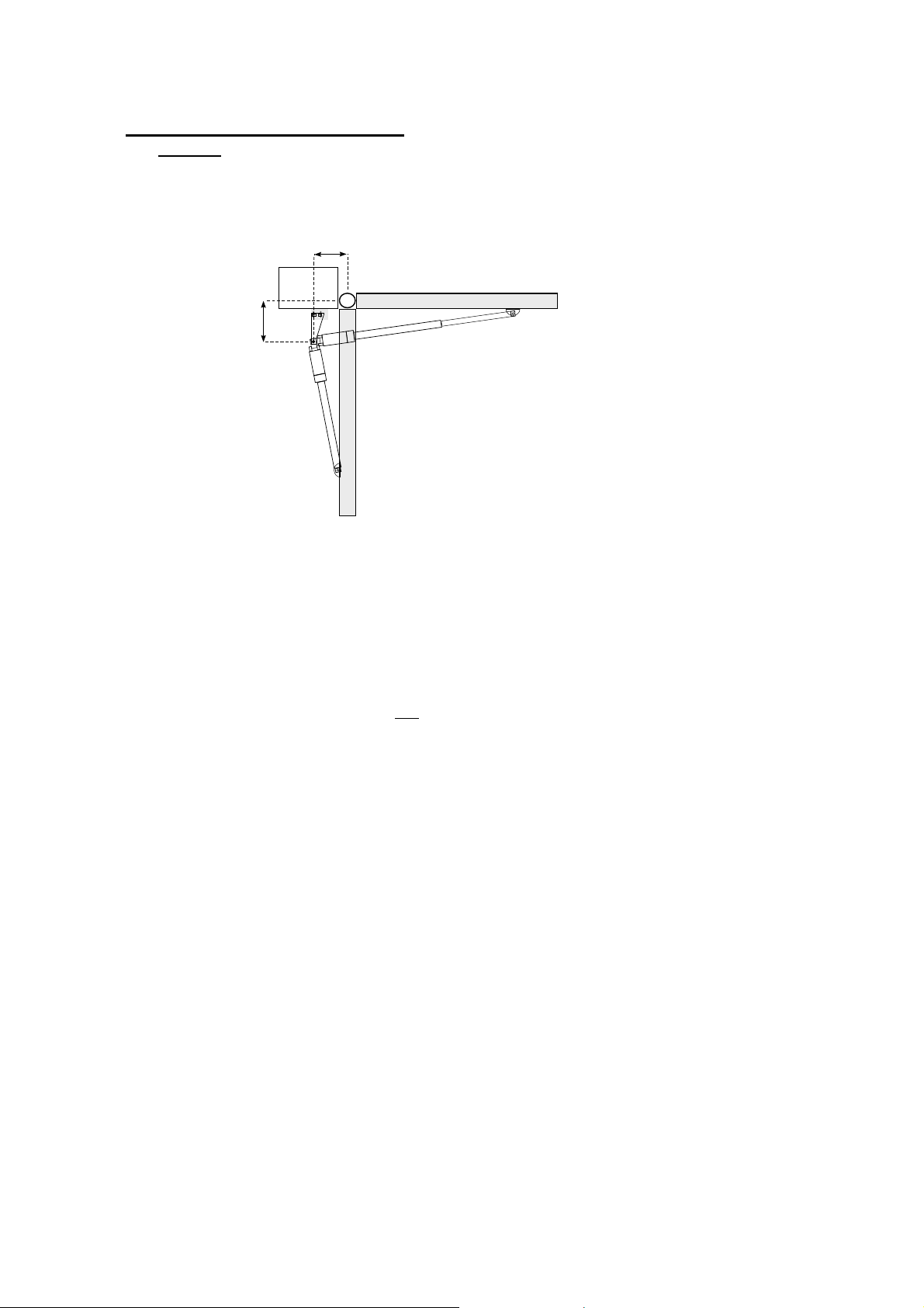
Gate Post Bracket Positioning
In a standard installation the basic aim is to get the “J” and “K” dimensions to be as close
as possible to equal but “J” can be greater allowing for a more positive push of the gate
against gate stop.
Hint: The dimension of J and K for a standard installation is approximately
For 400 mm Stroke Arm, start with J = (200 - 220) mm, K = (200 – 240) mm
K
J
Gate Preparation for Automatic Gate System installation.
Before you install the automatic arms to your gate, ensure that the gate is properly
constructed and must be leveled.
The hinge bearings must be in good condition and gate swings smoothly for both
opening and closing. Tight spots in opening and/or closing suggest that the hinge
bearings are worn and need to be rectified before you install the automatic system.
The gate must not hit or drag across the ground or be fitted with a wheel.
A properly leveled gate will not have tendency to self-open or self-close but remain
stationery. A self-opening or self-closing gate suggests that the gate is not leveled.
This will cause accelerated wear to your automatic gate system. Level the gate
properly before installing the automatic gate system.
Close the gate to full-close position and install the gate stopper (floor rubber
stopper and gate tabs). Installing the gate stopper allows for the automatic arm to
push the gate firmly against the ground stopper to ensure a solid close and proper
alignment between the left and right leafs of the gate.
You may choose to install another gate stopper at the full-open position, or you may
choose to let the gate swing till it is stopped by the internal built-in stop mechanism
when the arm is fully retracted.
Installation Pointers
The proper position of the gate post bracket (primary wall bracket and secondary wall
bracket) and gate bracket is crucial to the efficiency and leverage of the gate opener.
Attention needs to be paid to both its correct height and its position on the post in respect to
the relationship between your hinge pivot point and the motor pivot point on the bracket.
Once you have determined the general desired height of the motor, position the bracket and
take note of the dimensions.
Hint : It’s best to locate the gate opener arms in approximately the middle between the top
and bottom of the gate. This will prevent the gate from twisting and flexing.
E8 Swing Automatic Gate. Revision 1.1.8 –1112
4 of 19
Page 5
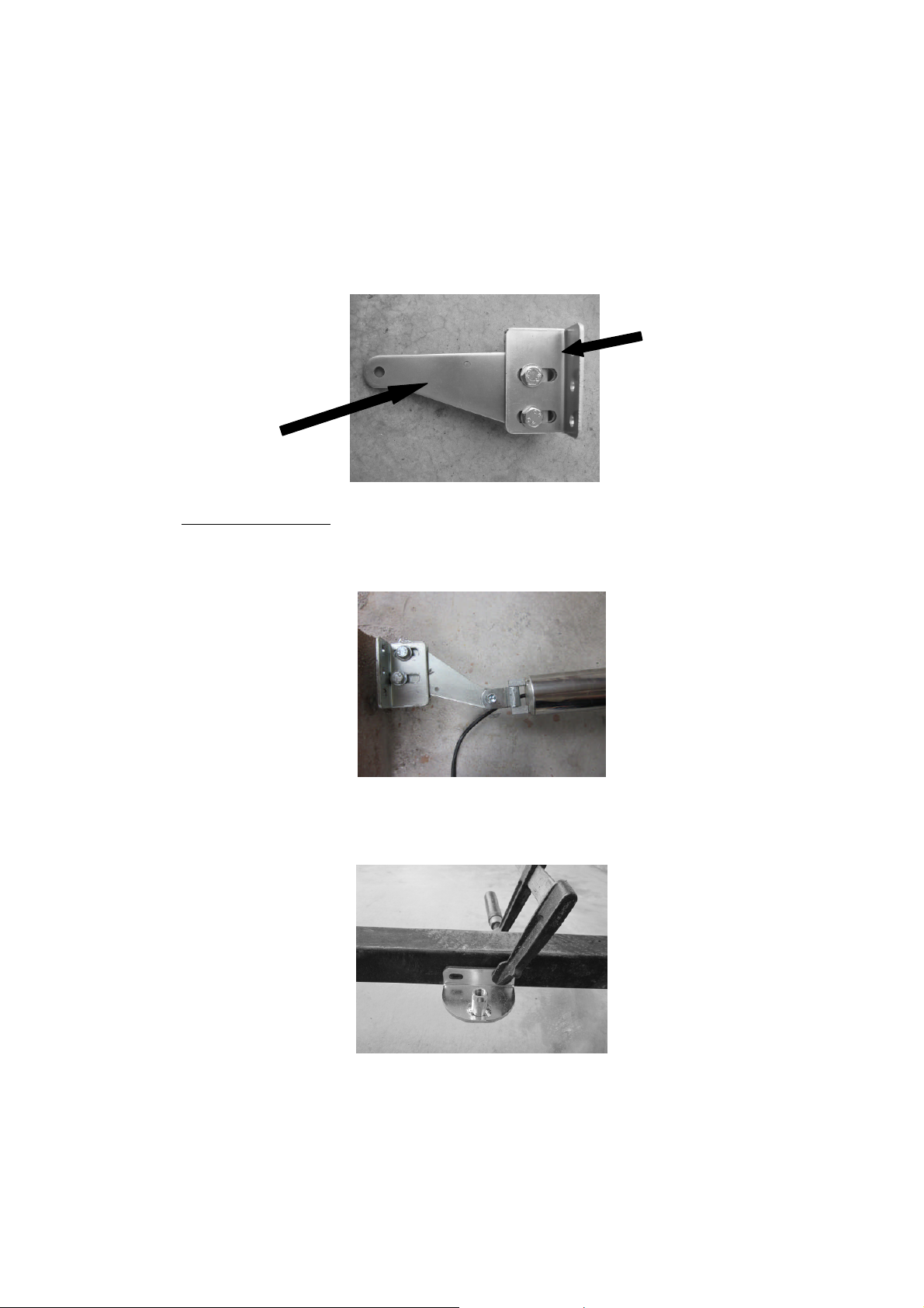
Installing Gate Post Brackets and the Arms (Push-to-Close/ Pull-toOpen)
Retract the arms (you can use the backup battery to help retract the Arms) and open
the gates to the fully-opened position.
Assemble the gate post brackets (Primary Wall Bracket and Secondary Wall
Bracket) by placing the secondary wall bracket between the middle gap of the
primary wall bracket. Do not tighten the nylon nut yet.
Primary
Wall
Bracket
Secondary
Wall
Bracket
400mm Stroke Arm. Place the gate post brackets in a position whereby the distance
of [J] and [K] are approximately [J = 200 - 220mm] and [K = 200 - 240mm] –from
the centre of the gate hinge bearing. (refer to Figure 1)
Attached the retracted arms onto the gate post bracket assembly.
Pivot the arms on the gate post brackets towards the gate.
At the position in which the arms contact the gate, temporarily hold the gate
bracket with a clamp. This marks the position of the gate bracket.
Extend the Arms to close the gates.
To extend the Arms use the backup battery supplied in your packing.
E8 Swing Automatic Gate. Revision 1.1.8 –1112
5 of 19
Page 6
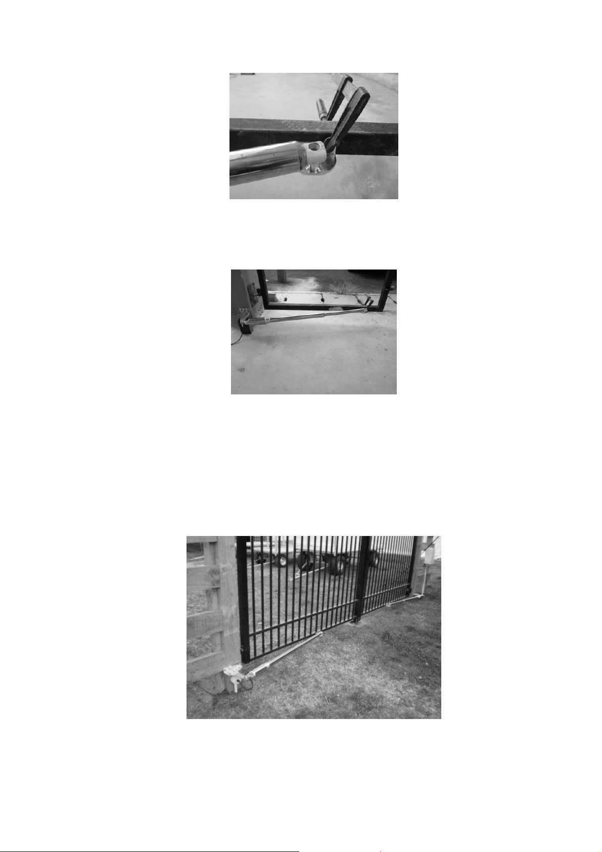
The arms should be approximately 10-15mm from full extension when the gate
completely closes against the floor rubber stopper.
o This is to ensure that when in operation, the arms will give a solid push to
the gate onto the floor stopper.
If the gate does not fully close, even when the arms have fully extended, re-adjust
the gate post brackets position.
o A smaller [K] is necessary if gate does not fully close
o A bigger [J] will allow for a more positive push of the gate towards the floor
stopper.
Once the final position of the gate post has been determined, secure the gate post
brackets onto the pillar(s).
Repeat the same procedure for the second gate leaf (Double).
E8 Swing Automatic Gate. Revision 1.1.8 –1112
6 of 19
Page 7
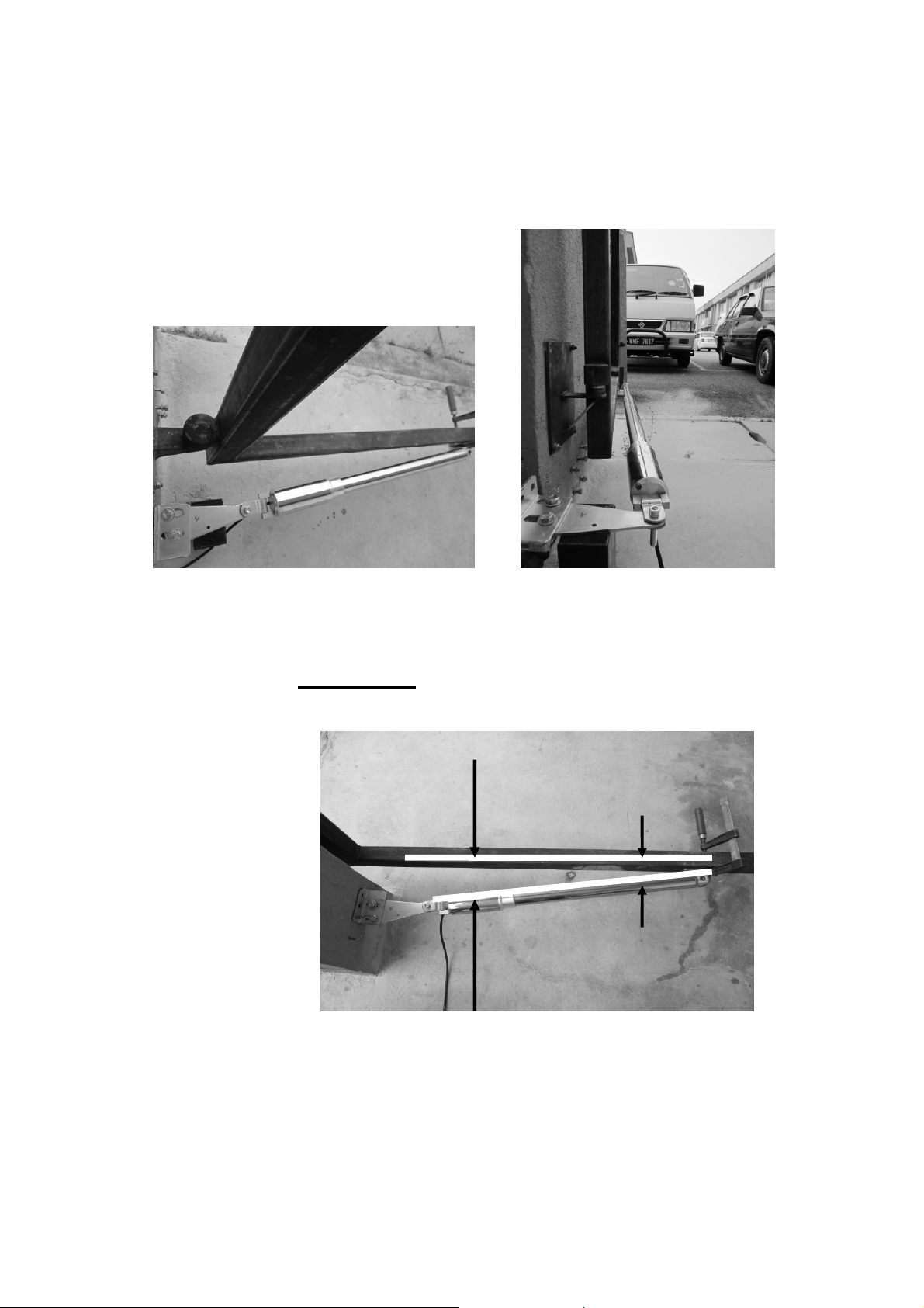
Installing Gate Post Brackets and the Arms for Push-to-Open Gates
Installation method for push-to-open gates is similar to pull-to-open except that
when the arms are retracted, the gates are in the closed position.
Note that for push-to-open gate, the gate post bracket arms pivot point is the on the
same plane as the gate hinge pivot.
Push-to-Open Gate (Fully closed) Push-to-Open Gate (Fully Opened)
Important Note (Non-Parallel of Arms and Gate):
When the gate is Fully Opened or Fully Closed, the Arms must NOT be parallel with the
gate.
Gate and Arms
Must NOT be
Parallel
Shown here is the Pull-To-Open Setup in the Fully-Opened position
E8 Swing Automatic Gate. Revision 1.1.8 –1112
7 of 19
Page 8
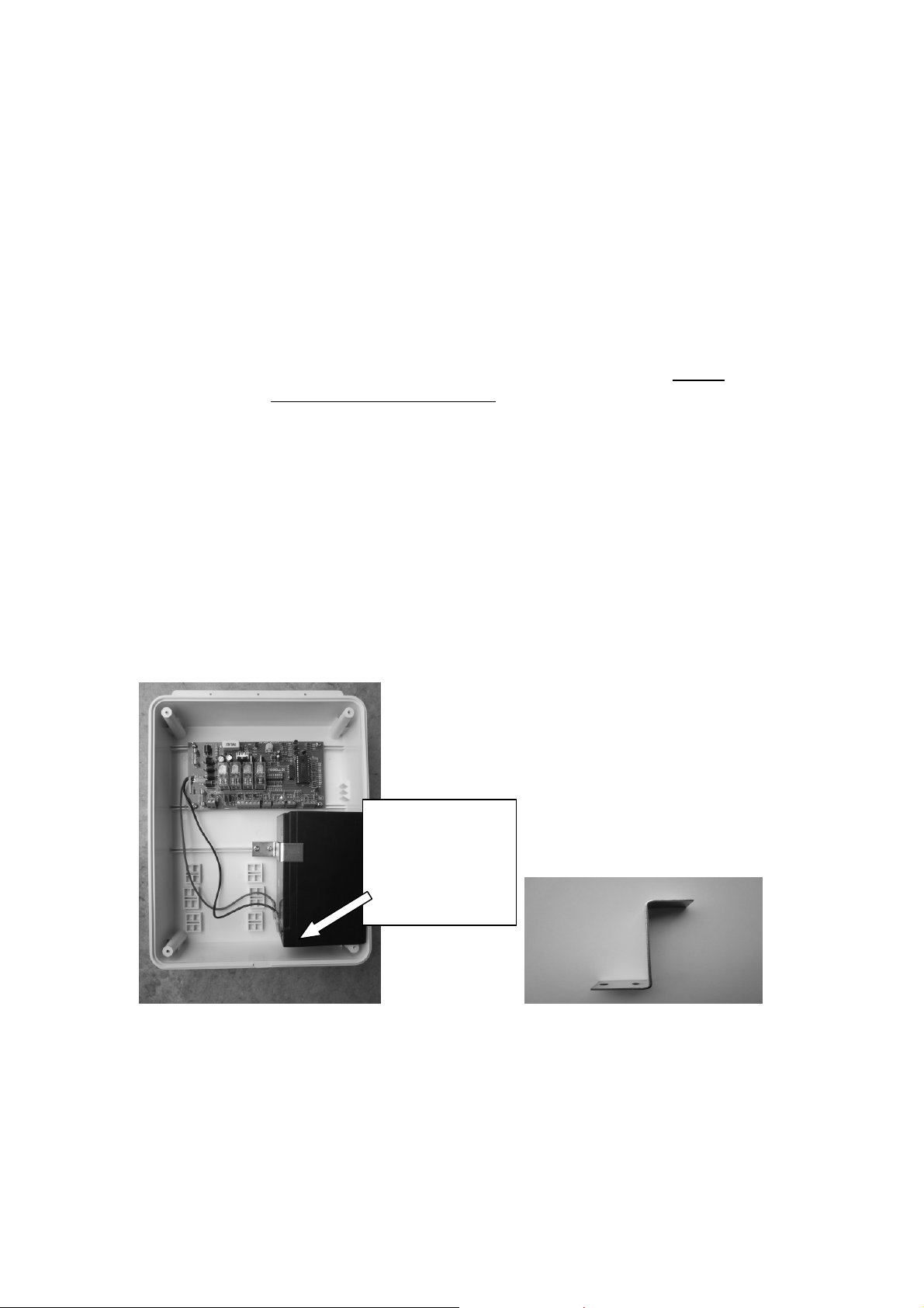
Mounting of the Control Panel Box
Select a flat and sturdy surface for the mounting of the control panel box.
Care must be taken to ensure that the mounting screws and holes on the control panel
are properly sealed to prevent water seepage into the control box.
Water damage of the boards will void the warranty.
Connection of Power Source (240Vac)
230Vac-16Vac Transformer
Transformer can be relocated up to around 30m from control box using a transformer
kit (in a protective electrical box with mains lead and plug) or positioned inside the
control box if mains power is available at the gate. In either option you MUST install
transformer via a RCD (residue current device) to avoid injury from shock as per local
government electrical requirements. Always switch off mains power when any work
is being carried out on or around gate installation. Always ensure that the transformer
is properly protected from water and dampness.
We recommend a minimum 2.5mm x 2 core TPS cable. Connect mains power supply
to the input cable at the transformer. Output cable 16Vac is connected to the D1
control board.
Connection and Mounting of Backup Battery
Your system is supplied with a 7amp-hour (transformer power) or 12amp-hour battery
and steel mounting brackets with screws. You must install battery in the right bottom
of your control board with the battery terminals at the bottom to avoid shorting of the
terminals onto the battery bracket.
Battery Terminal
on the Bottom.
Shown here
installation of
7AH Battery
Mounting of Battery in Control Panel Box Z Metal Battery Holding Bracket
E8 Swing Automatic Gate. Revision 1.1.8 –1112
8 of 19
Page 9

Control Panel – Model D1
The E8 D1 control panel is specially designed to match 12Vdc Arm Gate Motor(s).
The electronic panel requires no maintenance as long as the gate operates in proper
order and is kept dry and insect free. Mount the Control box as close to the motor(s)
(maximum 10m cable) as possible connected with minimum 1.5mm 2-core electrical
cable to reduce any voltage drop which will affect the performance of the system.
2.5mm to 4mm house cable is commonly used.
DIP SWITCH setting on the control board:
[1] ON = Delay Close motor A (MT A) for 2 seconds after MT B
- used in conjunction with solenoid lock
[1] OFF = Gate(s) open/close at same time
[2] ON = Small Reverse before opening used with 12V lock
[2] OFF = Gates open immediately without small reverse movement
[3] OFF & [4] OFF = LAMP ON (gate open) & cut off 1 min. after gate closed
[3] ON = LAMP permanently ON when Photocell detect dark ambient.
LAMP OFF, 1 minute after photocell detect bright ambient
[4] ON = LAMP output can be ON/OFF manually. Pressing [1-SIDE]
[COM] will toggle LAMP output.
Note : Single Arm operation no longer possible when DIP 4 is
ON
[5] ON = Single Gate Operation (MT A)
[6] OFF = Not in use
[7] OFF & [8] OFF = Disable Auto Close
[7] OFF & [8] ON = 030 sec. Auto Close
[7] ON & [8] OFF = 060 sec. Auto Close
[7] ON & [8] ON = 120 sec. Auto Close
On Solar Setup
For Solar powered setup, keep both DIP #3 and DIP #4 to [OFF] position.
E8 Swing Automatic Gate. Revision 1.1.8 –1112
9 of 19
Page 10

Setting the System :
Double Gate Operation (Both Pull-to-Open and Push-to-Open Gate)
1. Unplug AC power and Battery and make sure the gate(s) are completely
CLOSED.
2. After 30 seconds reconnect power to the system until short clicking from
board can be heard.
3. Press remote transmitter for gate(s). Let the motor open (low speed) until
gate(s) are fully opened. Check that the [MT A] and [MT B] LEDs are green.
If red LED is observed, disconnect power then reverse arm wire in question
and start setup again from step 1.
4. Both the motor will stop automatically when the gate is hard stopped. High
current cut-off by the circuit board is automatically achieved.
5. Press remote transmitter again and let the motor close (high speed) until both
gates are fully closed. [MT A] and [MT B] LEDs are Red. Both the motor will
stop automatically when the gate is hard stopped. High current cut-off by the
circuit board is automatically achieved.
The system has now stored the range between opening and closing time. The
microprocessor will automatically adjust the low speed and high speed opening /
closing of the system.
Setup is now complete.
6. Test each cycle a few times to make sure the microprocessor has stored the
correct range.
Note that :
The gate will auto reverse when the system detects obstruction (high
amp) during high speed closing operation.
The gate will stop when the system detects obstruction (high amp)
during opening operation.
To Reset :
To RESET the Memory, remove all power sources (Mains and
Battery). Wait for 30 seconds. System will reset the open / close
calibration. Repeat Step #1 – 5 to set the memory.
Note :
For Pull to Open Gate – Arm is fully extended in the gate-close position
For Push to Open Gate – Arm is fully retracted in the gate-close position
E8 Swing Automatic Gate. Revision 1.1.8 –1112
10 of 19
Page 11
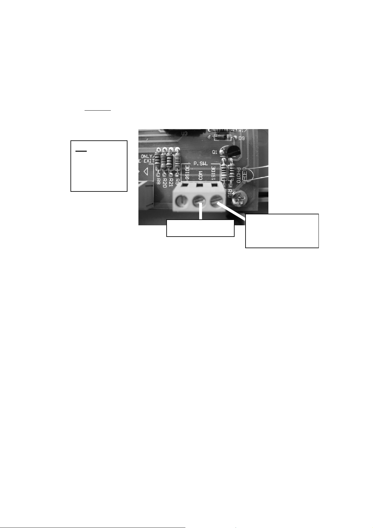
Single Gate Operation:
1. Set DIP switch [5] to ON position and connect arm motor wires to [MT A]
terminals.
2. Place / Connect both receiver output wires together (Yellow and Brown) into
the far right terminal [1 SIDE].
3. Place receiver common wire (White) into the [COM] terminal.
Note: Do NOT have any connection to [2 SIDE] terminal as this will confuse the
board and Motor B will not cut off.
NO
Connection to
[2 SIDE]
terminal for
Single Arm
2 SIDE
1 SIDE
COM
Receiver (COM)
4. Set the ARM in the CLOSE position and then power up the board.
5. Press the remote transmitter and observe GREEN Led indicating Opening
cycle on D1 board. Gate is running on Slow Speed. If it is RED then switch
OFF power and reverse the motor wire polarity to change the direction of the
motor. Return to step 3.
6. Board auto cutoff when high amp. GREEN Led will go off.
7. Press transmitter again. Gate should close. Observe the RED Led indicating
Closing cycle
8. In the 1 Arm operation, gate when fully closed (at high speed) the first time,
may reopen. This is ok.
9. Press the Transmitter again. Observe the RED Led indicating closing cycle.
10. When the gate is stopped, the RED Led will go off.
The system has now stored the range between opening and closing time. The
microprocessor will automatically adjust the low speed and high speed opening /
closing of the system.
Parallel Yellow and
Brown wire of
Receiver to [1 SIDE]
Setup is now complete.
7. Test each cycle a few times to make sure the microprocessor has stored the
correct range.
E8 Swing Automatic Gate. Revision 1.1.8 –1112
11 of 19
Page 12

Remote Control: The 12Vdc remote transmitter contains two signal represented by
button 1 and button 2 on your remotes. Confirm with owner which function they want
for each of the button.
Double gate setup button #1 can be set as single gate operation while button #2 is set
as double gate operation.
You can change this so that either button will activate BOTH gates by joining the
Yellow and the Brown wire at [2 SIDE] terminal.
You can relocate the receiver black box to another moisture-free location to increase
signal strength using cat.5 network cable.
Antenna: The green/blue wire is the antenna with a tuned length. DO NOT CUT.
You can increase the range by installing an additional long range antenna connected
to the green wire.
Adding New Remotes:
Remove the back panel of a remote (tiny Phillips screw) that is already working to
activate your gate. Match the new remote receiver DIP setting to the current remote
DIP switch setting.
Each DIP switch has 3 positions (top, middle and bottom) so care must be taken when
setting each DIP switch.
Check the signal transmission by pressing your new remote.
Changing Remote Codes:
The black Remote receiver Box has 5 wires connecting to your control board.
Remove the lid to view the code DIP switches.
If you change these you must also change all your remote DIP switches by removing
the back panel of each remote and match to the receiver DIP setting. Each switch has
3 positions (top, middle and bottom) so care must be taken when setting each DIP
switch. After the receiver panel is connected to the control panel, check signal
transmission. Test each of the remote individually.
Increase Range of the Remotes:
Connect a Long Range Antenna to the end of the green / blue antenna wire of the
receiver box. Place as high as possible in sight of the area you wish to transmit from.
You can relocate the transmitter box to another moisture-free location to increase
signal strength using cat.5 network cable.
E8 Swing Automatic Gate. Revision 1.1.8 –1112
12 of 19
Page 13

Solid Gate-Stops must be fitted in the center of driveway to give a solid pressure
point between the stop and the end of each gate. Place a gate stop at the fully open
position if desired.
Arm Condensation Drain Hole : Always mount arms with condensation drain holes
facing down or water will enter motors and damage the electrics voiding the warranty.
This is indicated on your arm with the “THIS SIDE DOWN” marking.
Wiring Double Gates: Connect your arms to block [MT A] and [MT B]. We
recommend 1.5mm wire or greater. Lighter cable will restrict the performance of the
system. Use a suitable electrical junction box to protect cable joints from moisture
damage.
Check Motor Rotation Direction: After power supply has been connected to the
Control Panel, make sure the gate swings in the correct direction. The system will
initiate an OPEN signal (green LED on board) the first time the remote is pressed.
The second time the remote is pressed the system initiates a CLOSE function (red
LED on board). Both gates should either OPEN or CLOSE in tandem.
This is important as wrong direction will cause the system work in the reverse
manner.
Hint: Check the LED lights above [MT A] and [MT B]. Green indicates an OPEN
cycle and Red a CLOSE cycle. To reverse the direction of the motor, reverse the wire
polarity at the control panel.
Safety infrared beams:
Observe the [IR BEAM terminal] on the D1 board.
Connect the 12V of Photobeam to [PWR] and Common of Photobeam to [COM].
Connect the NC (normally closed) output of the photobeam to [COM] and [NC] on
the D1 board
Note: When installing the photobeam, you will need to remove the small loop /
jumper wire that is pre-positioned on your D1 board at [COM] and [NC]. Replace the
loop / jumper wire when beams are not in use.
Lock:
Used when a 12Vdc lock is used to keep gates from being forced open when fully
closed.
Connect to solenoid lock cables to the [LOCK] terminals on the D1 board.
Set DIP switch [1] & [2] to ON position. This allows for the gate to have a slight
reverse movement just prior to the disengaging of the solenoid lock.
E8 Swing Automatic Gate. Revision 1.1.8 –1112
13 of 19
Page 14
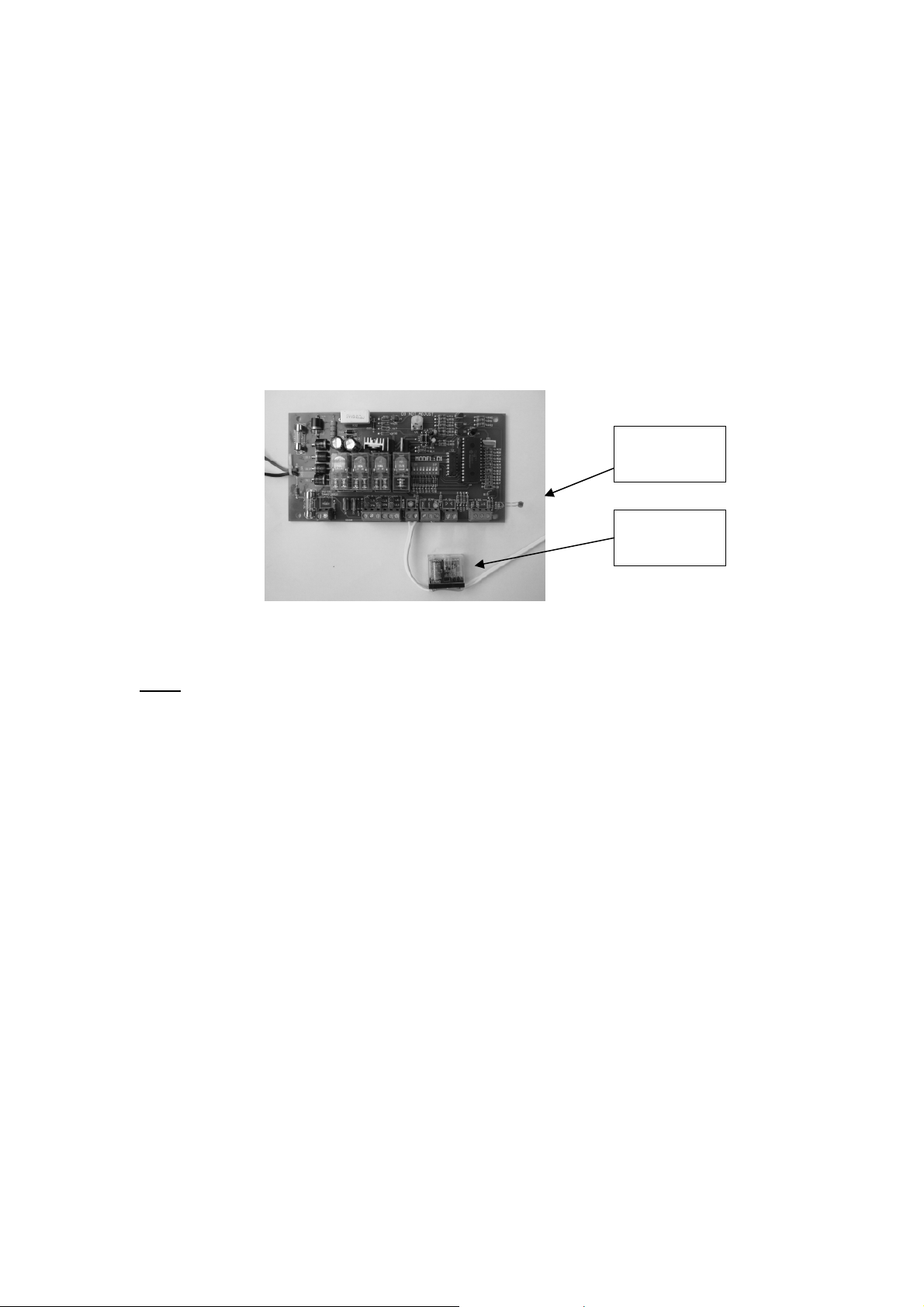
External Light connection
D1 board has a 12Vdc output on the Lamp Relay Terminal. Left terminal is negative
and right is positive.
This output is to energize an EXTERNAL 12Vdc relay which in turn can be used to
turn on /off a higher rating electrical item such as a Pillar Light.
Warning: All 240v wiring MUST be done by a qualified electrical person.
1. Set DIP Switch [3] and [4] to OFF Position.
2. In this setup, the LAMP output will be ON when the gate is open, and will
turn OFF 1 minute after the gate is closed.
3. Connect a 12Vdc relay as is shown in Figure 1.
Lamp
Photocell
Relay to
Lamp
Figure 1: Connection of 12Vdc Relay for 240V lights
Note: D1 board is designed with a Lamp Photocell (bottom right side of D1 board), so
that Lamp Relay will NOT be activated in Bright Ambient.
When connected to Pillar Lights, this design prevents the Pillar Light from turning
ON during the Day.
Please note however, that due to the different lighting intensity, direction of lights,
reflection etc in the Control Panel Box, it is possible that that Lamp Relay is activated
even if the external ambient is significantly bright.
If you wish that the Pillar Lights to be turned on, irrespective of the ambient lighting,
use a Dark Tape to cover the Lamp Photocell or turn the Photocell inwards when
mounted in the Control Box.
Point the lamp photocell to the side Gills of the supplied box for ambient light
detection.
E8 Swing Automatic Gate. Revision 1.1.8 –1112
14 of 19
Page 15

Trouble-Shooting.
Problem: The system does not response when transmitter is pressed.
Solution:
Make sure the transmitter in good condition. Ensure that the battery is
functioning and the LED on the transmitter lights up when button is pressed.
Replace battery if transmitter only works at very close range to the receiver.
Check the receiver by removing the Control Box cover and view the inside of
the Black Receiver Box for insects.
Check the wiring of the receiver panel and make sure the power is connected
in correct polarity. Check the power from control board to ensure there is
12Vdc to receiver.
Try other optional activation devises such as Exit Button or Keypad. If
hardwired devices activate the gate but all transmitters do not, recheck the
Black Receiver Box.
Check arms (s) are working using the power directly from the battery.
Check wires are connected properly to the control board.
Problem: The gate does not fully open and close, or stops half way.
Solution:
Ensure there is no obstruction to the movement of the gate. This could also be
high resistance such as poor gate installation or high winds activating the antiobstruction sensing. This can be verified by releasing the gate to Emergency
release mode (remove the arms actuator from the gate). Manually push the
gate open and close to detect any obstruction.
Ensure that on the first setting setup, the gate is fully closed before the board is
initialized. Short distance detection will result in error of count for the total
time of the gate swing.
Ensure that the when the arm actuators are removed from the gate, the gate
does not have a tendency to swing open or close but stays stationery. As selfopening or self-closing gate is a poorly constructed gate. Such a gate will
cause an uneven force for opening and closing stroke.
E8 Swing Automatic Gate. Revision 1.1.8 –1112
15 of 19
Page 16

Problem: The gate will open but not close.
Solution:
Check the wire loop is still in place on {IR Beam} block between terminal
[NC] and [COM].
If photobeams are fitted, check beam wiring/setup/ obstructions.
Problem: The gate does not travel smoothly when opening or closing.
Solution:
Ensure there is no obstruction to the movement of the gate such as hitting the
ground. This can be verified by releasing the gate to Emergency release mode.
Manually swing the gate open / close to detect any tight spots.
Ensure that the gate is properly leveled and that the dimension guide for the
installation of the Automatic gate is followed.
Arm actuators must not be parallel to the gate when fully open or fully closed.
Problem: On double gate setup, one gate closes fully before the 2ndgate starts.
Solution:
System is running on battery only (eg. Solar setup) and transformer AC not
connected. Check power with voltmeter.
(does not apply to Version 1.3.0 chip. In Version 1.3.0 chip both gates will always
close simultaneously even when running on Battery mode)
E8 Swing Automatic Gate. Revision 1.1.8 –1112
16 of 19
Page 17
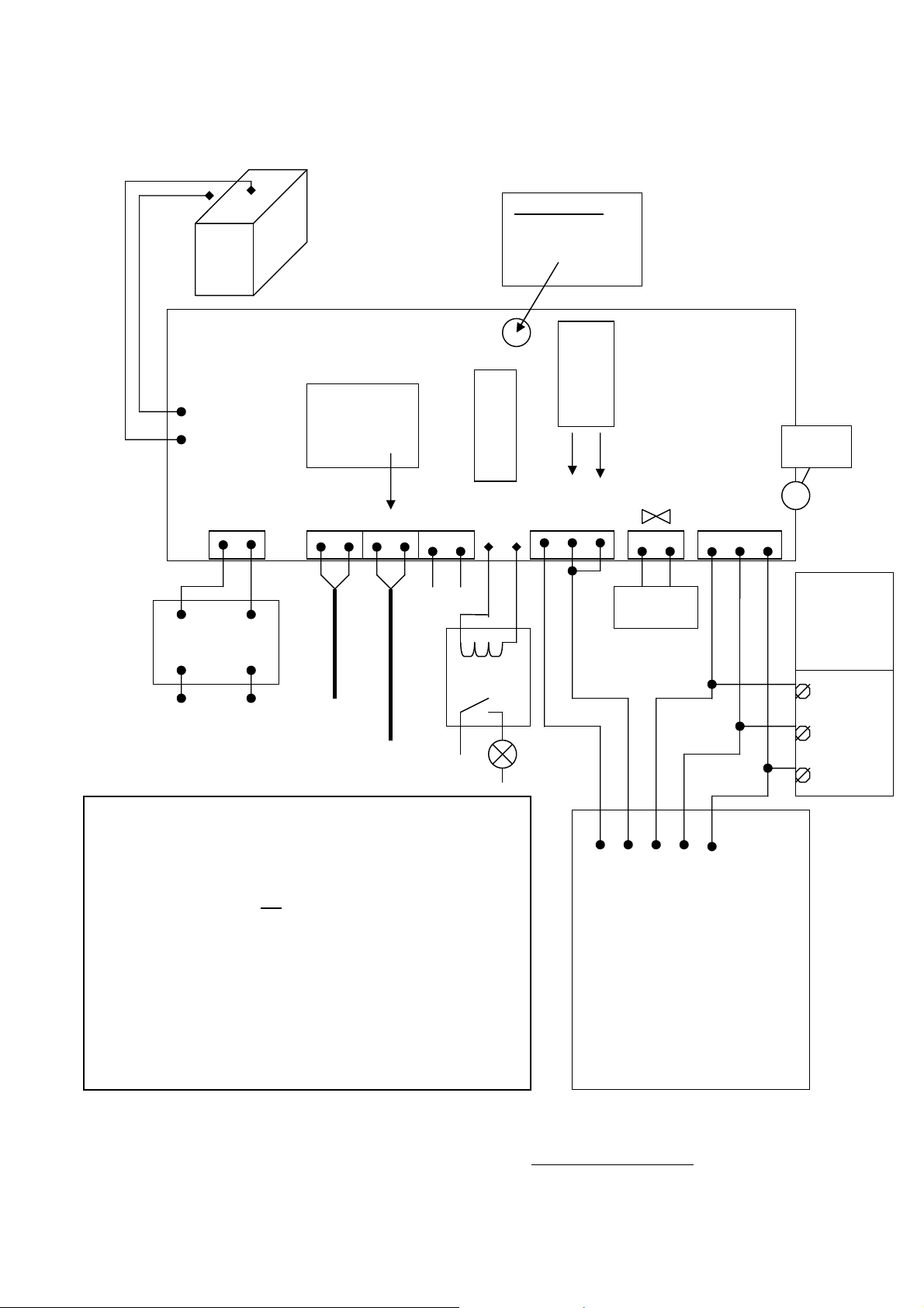
D1 Swing Gate Wiring Diagram for TRANSFORMER
+ Red
REMOTE CONTROL RECEIVER
Do not adjust
(Remove wire)
sensor
Only Port
dial
at top of board is
BATTERY
For single
arm use only
Motor A and
DIP 5 ON
for battery
charging voltage
12v Lamp relay
12v+PWR
Safety Beams
2 SIDE
Light
1 SIDE
COM
16 V AC
16V AC0V AC
MT B MT A
LOCK
12V Light
relay
MOTOR B
AC 240V
MAIN SUPPLY to
transformer
MOTOR A
L
N
Setting the Dip Switch on the control board:
[1] ON = Delay Close Motor A for 2 seconds
[2] ON = Small Reverse before Opening (for Solenoid Lock use)
[3] OFF & [4] OFF = Light ON (gate open) & cut off 1 min.
after gate closed
[5] ON = Single Gate Operation (MT A) for external Push Switch
[6] OFF = Not in use
[7] & [8] OFF = Disable Auto Close
[7] OFF & [8] ON = 30 Sec. Auto Close
[7] ON & [8] OFF = 60 Sec. Auto Close
[7] ON & [8] ON = 120 Sec. Auto Close
Ff
PILLAR
LAMP
COM
NC
Close
V+ (RED)
V- (BLACK)
CM (WHITE)
C1 (BROWN)
C2 (YELLOW)
BOX
To use both remote buttons to
activate 2 gates, connect C2
Yellow to C1 Brown to [both gate]
For single gate connect the Brown
and Yellow together in the [1/2]
(GREEN /BLUE)
HOUSE
PUSH
BUTTON
and / or
KEYPAD
Double
Side
Common
Single
Side
ANTENNA
IMPORTANT NOTE : TRANSFORMER, BATTERY AND REMOTE RECEIVER MUST BE
KEPT IN THE CONTROL PANEL BOX, OUT OF WEATHER
E8 Swing Automatic Gate. Revision 1.1.8 –1112
17 of 19
Page 18

LIMITED WARRANTY
E8 warrants the original purchaser that for a period of twelve months from the date of purchase, the
product shall be free of defects in materials and workmanship under normal use. During the warranty
period, E8 shall, as its option, repair or replace any defective product upon return of the product to its
factory, at no charge for labour and materials. Any replacement and/or repaired parts are warranted for
the remainder of the original warranty or ninety (90) days, whichever is longer. The original owner
must promptly notify E8 in writing that there is defect in material or workmanship; such written notice
shall be received in all events prior to expiration of the warranty.
International Warranty
The warranty for international customers is as the same as for any customer within Malaysia, with the
exception that E8 shall not be responsible for any customs fees, taxes, or VAT that may be due.
Warranty Procedure
To obtain service under this warranty, please return the item(s) in question to the point of purchase. All
authorized distributors and dealers have a warranty program. Anyone returning goods to E8 must first
obtain an authorization number. E8 will not accept any shipment for which prior authorization has not
been used.
Conditions to Void Warranty
This warranty applies only to defects in pairs and workmanship relating to normal use. It does not
cover:
damage incurred in shipping or handling
damage caused by disaster such as fire, flood, wind, earthquake or lightning
damage due to causes beyond the control of E8 such as excessive voltage, mechanical shock
or water damage
damage caused by unauthorized attachment, alterations, modifications, or foreign objects.
damage caused by peripherals (unless such peripherals were supplied by E8)
defects caused by failure to provide a suitable installation environment for the products
damage caused by used of the products for purpose other than those for which it was designed.
damage from improper maintenance
damage arising out of any other abuse, mishandling, and improper application of the products.
E8’s liability for failure to repair the product under this warranty after a reasonable number of attempts
will be limited to a replacement of the product, as the exclusive remedy for breach of warranty. Under
no circumstances shall E8 be liable for any special, incidental, or consequential damages based upon
breach of warranty, breach of contract, negligence, strict liability, or any other legal theory. Such
damages include, but are not limited to, loss of profits, loss of the product or any associated equipment,
cost of capital, cost of substitute or replacement equipment, facilities or services, down time,
purchaser’s time, the claims of third parties, including customers, and injury to property.
Disclaimer of Warranties
This warranty contains the entire warranty and shall be in lieu of any and all other warranties, whether
expressed or implied (including all implied warranties of merchantability or fitness for a particular
purpose). And of all other obligations or purporting to act on its behalf to modify or to change this
warranty, nor to assume for it any other warranty or liability concerning this product.
WARNING: E8 recommends the entire system be completely tested on a regular basis. However,
despite frequent testing, and due to, but not limited to, criminal tampering or electrical disruption, it is
possible for this product to fail to perform as expected.
Out of Warranty Repairs
E8 will at this option repair or replace out-of-warranty products which are returned to its factory
according to the following conditions. Anyone returning goods to E8 must first obtain an authorization
number. E8 will not accept any shipment whatsoever for which prior authorization has not been
obtained. Products which E8 determines to be repairable will be repaired and returned. A set fee which
E8 has predetermined and which may be revised from time to time, will be charged for each unit
repaired. Products which E8 determines not repairable will be replaced by the nearest equivalent
product available at that time. The current market price for the replacement product will be charged for
each replacement unit.
E8 Swing Automatic Gate. Revision 1.1.8 –1112
18 of 19
Page 19

WARNING Please Read Carefully
Important Notice
An auto gate system cannot prevent burglary. It is only a replacement way for user to open the door.
Auto gate systems are generally very reliable but they may not work under all conditions and they are
not a substitute for prudent security practices or life and property insurance. Your auto gate system
should be installed and serviced by qualified security professionals who should instruct you on the
level of protection that has been provided and on the system operations.
Note to Installers
This warning contains vital information. As the only individual in contact with systems user, it is your
responsibility to bring each item in this warning to the attention of the users of this system.
System Failures
This system has been carefully designed to be as effective as possible. There are circumstances,
however, involving fire, burglary, or other types of emergencies where it may not provide protection.
Any auto gate system of any type may be compromised deliberately or may fail to operate as expected
for a variety of reasons. Some but not all of these reasons may be:
Inadequate Installation
A security system must be installed properly in order to provide adequate protection. Every installation
should be evaluated by a security professional to ensure that all measurement is correct.
Criminal Knowledge
This system contains security features which were known to be effective at the time of manufacture. It
is possible for persons with criminal intent to develop techniques which reduce the effectiveness of
these features. It is important that an auto gate system be reviewed periodically to ensure that its
features remain effective and that it be updated or replaced if it is found that it does not provide the
protection expected.
Power Failure
Control units require an adequate power supply for proper operation. If a device operates from
batteries, it is possible for the batteries to fail. Even if the batteries have not failed, they must be
charged, in good condition and installed correctly. If a device operates only by AC power, any
interruption, however brief, will render that device inoperative while it does not have power. Power
interruptions of any length are often accompanied by voltage fluctuations which may damage
electronic equipment such as security system. After a power interruption has occurred, immediately
conduct a complete system test to ensure that the system operates as intended.
Failure of Replaceable Batteries
The expected battery life is a function of the device environment, usage and type. Ambient conditions
such as high humidity, high or low temperatures, or large temperature fluctuations may reduce the
expected battery life. Low battery condition will cause the system in low power condition and having
problem functioning as usual. Regular testing and maintenance will keep the system in good operating
condition.
Compromise of Radio Frequency (Wireless) Devices
Signals may not reach the receiver under all circumstances which could include metal objects placed on
or near the radio path or deliberate jamming or other inadvertent radio signal interference.
Component Failure
Although every effort has been made to make this system as reliable as possible, the system may fail to
function as intended due to the failure of a component.
Inadequate Testing
Most problems that would prevent an auto gate system from operating as intended can be found by
regular testing and maintenance. The complete system should be tested weekly and immediately after a
break-in, an attempted break-in, a fire, a storm, an earthquake, an accident, or any kind of construction
activity inside or outside the premises.
Security and Insurance
Regardless of its capabilities, an auto gate system is not a substitute for property of life insurance. An
auto gate system also is not a substitute for property owners, renters, or other occupants to act
prudently to prevent or minimize the harmful effects of an emergency situation.
E8 Swing Automatic Gate. Revision 1.1.8 –1112
19 of 19
 Loading...