

Page 1

SRM-3006
Selective Radiation Meter
Operating Manual
Page 2

Narda Safety Test Solutions GmbH
Sandwiesenstraße 7
72793 Pfullingen, Germany
© 2010
Order no.: 3006/98.21
Issue: 03/04.2010, A ...
Previous issues: 02/11.2009, A ...
Subject to change.
Our normal terms of warranty and delivery
apply.
Printed in Germany
Page 3

Contents
Contents
1 Introduction . . . . . . . . . . . . . . . . . . . . . . . . . . . . . . . . . . . . . . . . . . . . . . 1
1.1 About this device . . . . . . . . . . . . . . . . . . . . . . . . . . . . . . . . . . . 2
1.2 SRM-3006 as a field strength meter . . . . . . . . . . . . . . . . . . . . 4
1.2.1 Basic unit . . . . . . . . . . . . . . . . . . . . . . . . . . . . . . . . . . . . . . . . . 5
1.2.2 Antennas . . . . . . . . . . . . . . . . . . . . . . . . . . . . . . . . . . . . . . . . . 5
1.2.3 Cables . . . . . . . . . . . . . . . . . . . . . . . . . . . . . . . . . . . . . . . . . . . 7
1.3 SRM-3006 as a laboratory device . . . . . . . . . . . . . . . . . . . . . . 8
1.3.1 Basic unit . . . . . . . . . . . . . . . . . . . . . . . . . . . . . . . . . . . . . . . . . 9
1.4 PC software . . . . . . . . . . . . . . . . . . . . . . . . . . . . . . . . . . . . . . . 9
1.5 About this operating manual . . . . . . . . . . . . . . . . . . . . . . . . . 10
1.5.1 User interface language. . . . . . . . . . . . . . . . . . . . . . . . . . . . . 10
1.5.2 Symbols and characters used . . . . . . . . . . . . . . . . . . . . . . . . 10
2 Important Safety Instructions . . . . . . . . . . . . . . . . . . . . . . . . . . . . . . 13
2.1 Using this operating manual . . . . . . . . . . . . . . . . . . . . . . . . . 14
2.2 Before connecting up. . . . . . . . . . . . . . . . . . . . . . . . . . . . . . . 14
2.3 Proper use . . . . . . . . . . . . . . . . . . . . . . . . . . . . . . . . . . . . . . . 14
2.4 Improper use . . . . . . . . . . . . . . . . . . . . . . . . . . . . . . . . . . . . . 15
2.5 General hazards . . . . . . . . . . . . . . . . . . . . . . . . . . . . . . . . . . 15
2.6 Dangers due to electromagnetic fields . . . . . . . . . . . . . . . . . 16
2.7 AC adapter / charger . . . . . . . . . . . . . . . . . . . . . . . . . . . . . . . 18
2.8 Rechargeable batteries . . . . . . . . . . . . . . . . . . . . . . . . . . . . . 19
2.8.1 Storage . . . . . . . . . . . . . . . . . . . . . . . . . . . . . . . . . . . . . . . . . 19
2.8.2 Handling . . . . . . . . . . . . . . . . . . . . . . . . . . . . . . . . . . . . . . . . 20
2.8.3 Fire hazards. . . . . . . . . . . . . . . . . . . . . . . . . . . . . . . . . . . . . . 20
2.8.4 Chemical hazards . . . . . . . . . . . . . . . . . . . . . . . . . . . . . . . . . 21
2.8.5 Charging and discharging . . . . . . . . . . . . . . . . . . . . . . . . . . . 21
2.8.6 Disposal . . . . . . . . . . . . . . . . . . . . . . . . . . . . . . . . . . . . . . . . . 22
2.9 Faults and unusual stresses . . . . . . . . . . . . . . . . . . . . . . . . . 22
2.10 Proper disposal . . . . . . . . . . . . . . . . . . . . . . . . . . . . . . . . . . . 22
Narda SRM-3006 I
Page 4

Contents
3 Connecting Up and Starting to Use the Device. . . . . . . . . . . . . . . . 23
3.1 Unpacking the device . . . . . . . . . . . . . . . . . . . . . . . . . . . . . . 24
3.1.1 Packaging . . . . . . . . . . . . . . . . . . . . . . . . . . . . . . . . . . . . . . . 24
3.1.2 Package contents . . . . . . . . . . . . . . . . . . . . . . . . . . . . . . . . . 24
3.1.3 Checking the device for shipping damage . . . . . . . . . . . . . . 24
3.1.4 Recovery after shipping and storage . . . . . . . . . . . . . . . . . . 24
3.2 Device overview . . . . . . . . . . . . . . . . . . . . . . . . . . . . . . . . . . 25
3.2.1 Display and control panels . . . . . . . . . . . . . . . . . . . . . . . . . . 25
3.2.2 Device side panel with antenna / cable connectors . . . . . . . 26
3.2.3 Device side panel with battery compartment . . . . . . . . . . . . 26
3.2.4 Device side panel with external connectors . . . . . . . . . . . . . 27
3.3 Power supply . . . . . . . . . . . . . . . . . . . . . . . . . . . . . . . . . . . . 27
3.3.1 Operation from battery pack . . . . . . . . . . . . . . . . . . . . . . . . . 28
3.3.2 Handling battery packs . . . . . . . . . . . . . . . . . . . . . . . . . . . . . 29
3.3.3 Operation from AC adapter / charger . . . . . . . . . . . . . . . . . . 30
3.4 Fitting the antenna . . . . . . . . . . . . . . . . . . . . . . . . . . . . . . . . 30
3.4.1 Fitting a Narda antenna directly on the Basic Unit . . . . . . . . 30
3.4.2 Connecting a Narda antenna
to the Basic Unit using a Narda cable. . . . . . . . . . . . . . . . . . 31
3.4.3 Using commercially-available cables and antennas . . . . . . . 33
3.4.4 Fitting a Narda antenna on a tripod . . . . . . . . . . . . . . . . . . . 33
4 Operation and Basic Settings . . . . . . . . . . . . . . . . . . . . . . . . . . . . . . 39
4.1 Controls . . . . . . . . . . . . . . . . . . . . . . . . . . . . . . . . . . . . . . . . 40
4.1.1 Rotary control and keys . . . . . . . . . . . . . . . . . . . . . . . . . . . . 40
4.1.2 Softkeys . . . . . . . . . . . . . . . . . . . . . . . . . . . . . . . . . . . . . . . . 41
4.2 Switching the device on and off . . . . . . . . . . . . . . . . . . . . . . 41
4.3 LCD screen elements . . . . . . . . . . . . . . . . . . . . . . . . . . . . . . 42
4.3.1 The upper status bar. . . . . . . . . . . . . . . . . . . . . . . . . . . . . . . 43
4.3.2 The lower status bar . . . . . . . . . . . . . . . . . . . . . . . . . . . . . . . 44
4.3.3 The navigator bar . . . . . . . . . . . . . . . . . . . . . . . . . . . . . . . . . 45
4.3.4 Activating / deactivating status and info bars . . . . . . . . . . . . 45
II SRM-3006 Narda
Page 5

Contents
4.4 Fundamental operating steps . . . . . . . . . . . . . . . . . . . . . . . . 46
4.4.1 Navigating in the menus . . . . . . . . . . . . . . . . . . . . . . . . . . . . 46
4.4.2 Selecting entries from a list . . . . . . . . . . . . . . . . . . . . . . . . . . 47
4.4.3 Changing numerical values . . . . . . . . . . . . . . . . . . . . . . . . . . 49
4.4.4 Entering text. . . . . . . . . . . . . . . . . . . . . . . . . . . . . . . . . . . . . . 50
4.4.5 Softkeys with toggle function . . . . . . . . . . . . . . . . . . . . . . . . . 51
4.4.6 Creating a screenshot . . . . . . . . . . . . . . . . . . . . . . . . . . . . . . 51
5 The Main Menu . . . . . . . . . . . . . . . . . . . . . . . . . . . . . . . . . . . . . . . . . . 53
5.1 Overview of functions and operating modes . . . . . . . . . . . . . 54
5.2 Display and editing device and component settings . . . . . . . 55
5.2.1 Changing the language, date, and time . . . . . . . . . . . . . . . . . 56
5.2.2 Editing device-specific settings . . . . . . . . . . . . . . . . . . . . . . . 57
5.2.3 Displaying device information . . . . . . . . . . . . . . . . . . . . . . . . 58
5.2.4 Displaying GPS information. . . . . . . . . . . . . . . . . . . . . . . . . . 59
5.2.5 Resetting all device settings . . . . . . . . . . . . . . . . . . . . . . . . . 59
5.2.6 Performing device diagnosis . . . . . . . . . . . . . . . . . . . . . . . . . 60
5.2.7 Displaying and selecting the available antennas . . . . . . . . . . 61
5.2.8 Displaying and selecting the available cables . . . . . . . . . . . . 61
5.2.9 Displaying and selecting the safety standards. . . . . . . . . . . . 62
5.2.10 Displaying and creating service tables . . . . . . . . . . . . . . . . . 62
5.3 The memory menu . . . . . . . . . . . . . . . . . . . . . . . . . . . . . . . . 64
5.4 Using measurement routines . . . . . . . . . . . . . . . . . . . . . . . . . 65
5.4.1 Displaying measurement routines . . . . . . . . . . . . . . . . . . . . . 65
5.4.2 Starting a measurement routine . . . . . . . . . . . . . . . . . . . . . . 66
5.5 Saving and loading setups. . . . . . . . . . . . . . . . . . . . . . . . . . . 66
5.5.1 Saving settings as a setup. . . . . . . . . . . . . . . . . . . . . . . . . . . 66
5.5.2 Loading settings from a setup . . . . . . . . . . . . . . . . . . . . . . . . 66
5.5.3 Editing the setup list. . . . . . . . . . . . . . . . . . . . . . . . . . . . . . . . 67
5.5.4 Deleting setups . . . . . . . . . . . . . . . . . . . . . . . . . . . . . . . . . . . 67
5.5.5 Changing the switch on behavior. . . . . . . . . . . . . . . . . . . . . . 68
Narda SRM-3006 III
Page 6

Contents
6 Functions Common to More Than One Operating Mode . . . . . . . . 69
6.1 Overview of functions
common to more than one operating mode . . . . . . . . . . . . . 70
6.2 Setting the resolution bandwidth (RBW). . . . . . . . . . . . . . . . 71
6.2.1 Setting the video bandwidth (VBW) . . . . . . . . . . . . . . . . . . . 71
6.3 Setting the measurement range (Meas. Range). . . . . . . . . . 72
6.3.1 Manual measurement range selection . . . . . . . . . . . . . . . . . 73
6.3.2 Automatic measurement range search (MR Search) . . . . . . 74
6.3.3 Measurement input overload . . . . . . . . . . . . . . . . . . . . . . . . 74
6.4 Selecting the result type (Result Type) . . . . . . . . . . . . . . . . . 75
6.4.1 Average formation (Result type: Average) . . . . . . . . . . . . . . 76
6.4.2 Reset measurement values . . . . . . . . . . . . . . . . . . . . . . . . . 77
6.5 The Marker function . . . . . . . . . . . . . . . . . . . . . . . . . . . . . . . 77
6.5.1 Using the markers separately . . . . . . . . . . . . . . . . . . . . . . . . 78
6.5.2 Using both markers to determine a difference . . . . . . . . . . . 80
6.5.3 Displaying the marker data on the measurement screen . . . 82
6.5.4 Zooming to marker . . . . . . . . . . . . . . . . . . . . . . . . . . . . . . . . 83
6.6 Selecting an axis mode. . . . . . . . . . . . . . . . . . . . . . . . . . . . . 84
6.6.1 Measurement using a three axis antenna. . . . . . . . . . . . . . . 85
6.6.2 Measurement using a single axis antenna . . . . . . . . . . . . . . 86
6.7 Adjusting the Y axis . . . . . . . . . . . . . . . . . . . . . . . . . . . . . . . 88
6.8 Changing the displayed units . . . . . . . . . . . . . . . . . . . . . . . . 89
6.9 Noise suppression (Noise Thresh.) . . . . . . . . . . . . . . . . . . . 90
6.10 Measuring spatial average values (Spatial AVG) . . . . . . . . . 91
6.11 Changing operating mode
and keeping the same parameters . . . . . . . . . . . . . . . . . . . . 91
6.12 Useful shortcuts . . . . . . . . . . . . . . . . . . . . . . . . . . . . . . . . . . 92
6.12.1 Selecting a service table or a service . . . . . . . . . . . . . . . . . . 92
6.12.2 Saving a setup . . . . . . . . . . . . . . . . . . . . . . . . . . . . . . . . . . . 92
IV SRM-3006 Narda
Page 7

Contents
7 Safety Evaluation Mode . . . . . . . . . . . . . . . . . . . . . . . . . . . . . . . . . . . 93
7.1 About Safety Evaluation mode. . . . . . . . . . . . . . . . . . . . . . . . 94
7.2 Basic settings. . . . . . . . . . . . . . . . . . . . . . . . . . . . . . . . . . . . . 96
7.2.1 Selecting the display mode . . . . . . . . . . . . . . . . . . . . . . . . . . 96
7.2.2 Activating the beeper . . . . . . . . . . . . . . . . . . . . . . . . . . . . . . . 96
7.2.3 Showing and hiding services . . . . . . . . . . . . . . . . . . . . . . . . . 97
7.2.4 Setting the resolution bandwidth (RBW) . . . . . . . . . . . . . . . . 97
7.2.5 Setting the measurement range (Meas. Range) . . . . . . . . . . 98
7.2.6 Selecting the result type (Result Type) . . . . . . . . . . . . . . . . . 98
7.2.7 Measuring in the gaps between defined services (Others) . . 99
7.3 Using the Table view . . . . . . . . . . . . . . . . . . . . . . . . . . . . . . . 99
7.3.1 Changing the table displayed. . . . . . . . . . . . . . . . . . . . . . . . 100
7.3.2 Percentage display . . . . . . . . . . . . . . . . . . . . . . . . . . . . . . . 101
7.4 Using the Bar Graph view . . . . . . . . . . . . . . . . . . . . . . . . . . 103
7.4.1 Adjusting the Y axis (Y-Scale) . . . . . . . . . . . . . . . . . . . . . . . 103
7.4.2 Changing the displayed units (Unit) . . . . . . . . . . . . . . . . . . . 103
7.4.3 The Marker function. . . . . . . . . . . . . . . . . . . . . . . . . . . . . . . 104
7.5 Selecting an axis mode . . . . . . . . . . . . . . . . . . . . . . . . . . . . 104
8 Spectrum Analysis Mode . . . . . . . . . . . . . . . . . . . . . . . . . . . . . . . . . 105
8.1 About Spectrum Analysis mode . . . . . . . . . . . . . . . . . . . . . 106
8.2 Basic settings. . . . . . . . . . . . . . . . . . . . . . . . . . . . . . . . . . . . 106
8.2.1 Changing the frequency range . . . . . . . . . . . . . . . . . . . . . . 107
8.2.2 Setting the resolution bandwidth (RBW) . . . . . . . . . . . . . . . 108
8.2.3 Setting the video bandwidth (VBW) . . . . . . . . . . . . . . . . . . . 108
8.2.4 Changing the displayed units (Unit) . . . . . . . . . . . . . . . . . . . 108
8.2.5 Adjusting the Y axis (Y-Scale) . . . . . . . . . . . . . . . . . . . . . . . 109
8.3 Evaluating the measurement data (Evaluation). . . . . . . . . . 109
8.3.1 Displaying the peak values (Peak Table) . . . . . . . . . . . . . . . 110
8.3.2 Integrating measured values (Integration) . . . . . . . . . . . . . . 112
8.4 The Marker function (Marker) . . . . . . . . . . . . . . . . . . . . . . . 114
8.5 The Zoom function (Zoom) . . . . . . . . . . . . . . . . . . . . . . . . . 114
Narda SRM-3006 V
Page 8

Contents
9 Level Recorder Mode. . . . . . . . . . . . . . . . . . . . . . . . . . . . . . . . . . . . 117
9.1 About Level Recorder mode . . . . . . . . . . . . . . . . . . . . . . . . 118
9.2 Display overview. . . . . . . . . . . . . . . . . . . . . . . . . . . . . . . . . 119
9.2.1 Activating the beeper . . . . . . . . . . . . . . . . . . . . . . . . . . . . . 120
9.3 Basic settings . . . . . . . . . . . . . . . . . . . . . . . . . . . . . . . . . . . 120
9.3.1 Selecting the center frequency (Fcent). . . . . . . . . . . . . . . . 120
9.3.2 Setting the resolution bandwidth (RBW). . . . . . . . . . . . . . . 120
9.3.3 Setting the video bandwidth (VBW) . . . . . . . . . . . . . . . . . . 120
9.3.4 Setting the measurement range (Meas. Range). . . . . . . . . 121
9.3.5 Selecting the result type (Result Type) . . . . . . . . . . . . . . . . 121
9.4 Selecting an axis mode (Axis) . . . . . . . . . . . . . . . . . . . . . . 122
9.5 Using noise suppression (Noise Thresh.). . . . . . . . . . . . . . 122
10 Scope Mode . . . . . . . . . . . . . . . . . . . . . . . . . . . . . . . . . . . . . . . . . . . 123
10.1 About Scope mode . . . . . . . . . . . . . . . . . . . . . . . . . . . . . . . 124
10.2 Display overview . . . . . . . . . . . . . . . . . . . . . . . . . . . . . . . . . 124
10.3 Setting the measurement parameters . . . . . . . . . . . . . . . . 125
10.3.1 Limits of values that can be set . . . . . . . . . . . . . . . . . . . . . 126
10.3.2 Example 1: GSM. . . . . . . . . . . . . . . . . . . . . . . . . . . . . . . . . 127
10.3.3 Example 2: DECT telephone . . . . . . . . . . . . . . . . . . . . . . . 127
10.3.4 Example 3: WLAN . . . . . . . . . . . . . . . . . . . . . . . . . . . . . . . 128
10.3.5 Example 4: Remote automobile key (ISM band) . . . . . . . . 130
10.4 Using the trigger function . . . . . . . . . . . . . . . . . . . . . . . . . . 131
10.5 Evaluating the measurement results (Evaluation) . . . . . . . 133
11 UMTS Mode. . . . . . . . . . . . . . . . . . . . . . . . . . . . . . . . . . . . . . . . . . . . 135
11.1 About UMTS mode . . . . . . . . . . . . . . . . . . . . . . . . . . . . . . . 136
11.2 Display overview . . . . . . . . . . . . . . . . . . . . . . . . . . . . . . . . . 137
11.3 Explanation of measurement result display . . . . . . . . . . . . 138
11.3.1 Individual results . . . . . . . . . . . . . . . . . . . . . . . . . . . . . . . . . 138
11.3.2 Total result (Total) . . . . . . . . . . . . . . . . . . . . . . . . . . . . . . . . 138
VI SRM-3006 Narda
Page 9

Contents
11.3.3 Partial results for certain radio cells
(scrambling codes) . . . . . . . . . . . . . . . . . . . . . . . . . . . . . . . 139
11.3.4 Analog measurement result (Analog) . . . . . . . . . . . . . . . . . 139
11.4 Basic settings. . . . . . . . . . . . . . . . . . . . . . . . . . . . . . . . . . . . 139
11.4.1 Setting the center frequency (Fcent) . . . . . . . . . . . . . . . . . . 140
11.4.2 Showing and hiding services . . . . . . . . . . . . . . . . . . . . . . . . 140
11.4.3 Resetting the table (Reset Table) . . . . . . . . . . . . . . . . . . . . 140
11.4.4 Setting the measurement range (Meas. Range) . . . . . . . . . 141
11.4.5 Selecting the result type (Result Type) . . . . . . . . . . . . . . . . 141
11.4.6 Using an extrapolation factor . . . . . . . . . . . . . . . . . . . . . . . . 141
11.5 Performing a coverage measurement . . . . . . . . . . . . . . . . . 142
11.6 Using noise suppression (Noise Thresh.) . . . . . . . . . . . . . . 142
12 Spatial Averaging . . . . . . . . . . . . . . . . . . . . . . . . . . . . . . . . . . . . . . . 143
12.1 About the Spatial Averaging function. . . . . . . . . . . . . . . . . . 144
12.2 Description of averaging functions. . . . . . . . . . . . . . . . . . . . 145
12.2.1 Continuous. . . . . . . . . . . . . . . . . . . . . . . . . . . . . . . . . . . . . . 146
12.2.2 Discrete . . . . . . . . . . . . . . . . . . . . . . . . . . . . . . . . . . . . . . . . 147
12.2.3 Discrete Axis . . . . . . . . . . . . . . . . . . . . . . . . . . . . . . . . . . . . 148
12.3 Spatial Averaging – Continuous. . . . . . . . . . . . . . . . . . . . . . 149
12.4 Spatial Averaging – Discrete . . . . . . . . . . . . . . . . . . . . . . . . 151
12.5 Spatial Averaging – Discrete Axis . . . . . . . . . . . . . . . . . . . . 153
13 Measurement Data Memory . . . . . . . . . . . . . . . . . . . . . . . . . . . . . . . 157
13.1 About the Memory menu . . . . . . . . . . . . . . . . . . . . . . . . . . . 158
13.2 Viewing data sets. . . . . . . . . . . . . . . . . . . . . . . . . . . . . . . . . 159
13.3 Viewing screenshots . . . . . . . . . . . . . . . . . . . . . . . . . . . . . . 160
13.4 Saving measured values automatically . . . . . . . . . . . . . . . . 161
13.4.1 Conditional Storing of measured values . . . . . . . . . . . . . . . 161
13.4.2 Time Controlled Storing of measured values. . . . . . . . . . . . 163
13.4.3 Changing the comment modes . . . . . . . . . . . . . . . . . . . . . . 165
Narda SRM-3006 VII
Page 10

Contents
14 Maintenance and Repairs . . . . . . . . . . . . . . . . . . . . . . . . . . . . . . . . 167
14.1 Changing the battery pack . . . . . . . . . . . . . . . . . . . . . . . . . 168
14.2 Cleaning . . . . . . . . . . . . . . . . . . . . . . . . . . . . . . . . . . . . . . . 168
14.3 AC adapter / charger. . . . . . . . . . . . . . . . . . . . . . . . . . . . . . 169
15 PC Software . . . . . . . . . . . . . . . . . . . . . . . . . . . . . . . . . . . . . . . . . . . 171
15.1 PC software versions and functions . . . . . . . . . . . . . . . . . . 172
15.2 Connecting to the PC . . . . . . . . . . . . . . . . . . . . . . . . . . . . . 172
15.3 Working with the PC software. . . . . . . . . . . . . . . . . . . . . . . 173
16 Remote Control . . . . . . . . . . . . . . . . . . . . . . . . . . . . . . . . . . . . . . . . 175
16.1 About remote control . . . . . . . . . . . . . . . . . . . . . . . . . . . . . 176
16.2 Connecting to the PC . . . . . . . . . . . . . . . . . . . . . . . . . . . . . 176
16.3 Activating / deactivating remote control . . . . . . . . . . . . . . . 177
16.3.1 Solving problems . . . . . . . . . . . . . . . . . . . . . . . . . . . . . . . . 177
16.4 Syntax rules for remote control commands . . . . . . . . . . . . 177
16.4.1 Commands to the SRM-3006 . . . . . . . . . . . . . . . . . . . . . . . 177
16.4.2 SRM-3006 responses . . . . . . . . . . . . . . . . . . . . . . . . . . . . . 178
16.4.3 Example of a command sequence . . . . . . . . . . . . . . . . . . . 179
17 Specifications. . . . . . . . . . . . . . . . . . . . . . . . . . . . . . . . . . . . . . . . . . 181
17.1 SRM-3006. . . . . . . . . . . . . . . . . . . . . . . . . . . . . . . . . . . . . . 182
17.1.1 RF features . . . . . . . . . . . . . . . . . . . . . . . . . . . . . . . . . . . . . 182
17.1.2 Modes . . . . . . . . . . . . . . . . . . . . . . . . . . . . . . . . . . . . . . . . . 184
17.1.3 Measurement functions . . . . . . . . . . . . . . . . . . . . . . . . . . . 188
17.1.4 General specifications . . . . . . . . . . . . . . . . . . . . . . . . . . . . 190
17.2 Three axis E-field antenna 3501/03 . . . . . . . . . . . . . . . . . . 192
17.2.1 Characteristics . . . . . . . . . . . . . . . . . . . . . . . . . . . . . . . . . . 192
17.2.2 Uncertainty . . . . . . . . . . . . . . . . . . . . . . . . . . . . . . . . . . . . . 193
17.2.3 General specifications . . . . . . . . . . . . . . . . . . . . . . . . . . . . 193
17.3 Three axis E-field antenna 3502/01 . . . . . . . . . . . . . . . . . . 195
17.3.1 Characteristics . . . . . . . . . . . . . . . . . . . . . . . . . . . . . . . . . . 195
VIII SRM-3006 Narda
Page 11

Contents
17.3.2 Uncertainty . . . . . . . . . . . . . . . . . . . . . . . . . . . . . . . . . . . . . 196
17.3.3 General specifications . . . . . . . . . . . . . . . . . . . . . . . . . . . . . 196
17.4 Three axis H-field antenna 3581/02. . . . . . . . . . . . . . . . . . . 197
17.4.1 Characteristics . . . . . . . . . . . . . . . . . . . . . . . . . . . . . . . . . . . 197
17.4.2 Uncertainty . . . . . . . . . . . . . . . . . . . . . . . . . . . . . . . . . . . . . 198
17.4.3 General specifications . . . . . . . . . . . . . . . . . . . . . . . . . . . . . 198
17.5 Single axis E-field antenna 3531/01 . . . . . . . . . . . . . . . . . . 199
17.5.1 Characteristics . . . . . . . . . . . . . . . . . . . . . . . . . . . . . . . . . . . 199
17.5.2 Uncertainty . . . . . . . . . . . . . . . . . . . . . . . . . . . . . . . . . . . . . 199
17.5.3 General specifications . . . . . . . . . . . . . . . . . . . . . . . . . . . . . 200
17.6 Single axis E-field antenna 3531/04 . . . . . . . . . . . . . . . . . . 201
17.6.1 Characteristics . . . . . . . . . . . . . . . . . . . . . . . . . . . . . . . . . . . 201
17.6.2 Uncertainty . . . . . . . . . . . . . . . . . . . . . . . . . . . . . . . . . . . . . 201
17.6.3 General specifications . . . . . . . . . . . . . . . . . . . . . . . . . . . . . 201
17.7 Single axis H-field antenna 3551/02 . . . . . . . . . . . . . . . . . . 203
17.7.1 Characteristics . . . . . . . . . . . . . . . . . . . . . . . . . . . . . . . . . . . 203
17.7.2 Uncertainty . . . . . . . . . . . . . . . . . . . . . . . . . . . . . . . . . . . . . 203
17.7.3 General specifications . . . . . . . . . . . . . . . . . . . . . . . . . . . . . 203
17.8 Declaration of Conformity . . . . . . . . . . . . . . . . . . . . . . . . . . 205
18 Annex A . . . . . . . . . . . . . . . . . . . . . . . . . . . . . . . . . . . . . . . . . . . . . . . 207
18.1 Pendulum method . . . . . . . . . . . . . . . . . . . . . . . . . . . . . . . . 208
18.2 Matrix method (precision measurement) . . . . . . . . . . . . . . . 210
19 Ordering Information . . . . . . . . . . . . . . . . . . . . . . . . . . . . . . . . . . . . 213
19.1 SRM-3006 sets . . . . . . . . . . . . . . . . . . . . . . . . . . . . . . . . . . 214
19.2 Antennas . . . . . . . . . . . . . . . . . . . . . . . . . . . . . . . . . . . . . . . 215
19.3 Options . . . . . . . . . . . . . . . . . . . . . . . . . . . . . . . . . . . . . . . . 215
19.4 Accessories . . . . . . . . . . . . . . . . . . . . . . . . . . . . . . . . . . . . . 216
20 Glossary. . . . . . . . . . . . . . . . . . . . . . . . . . . . . . . . . . . . . . . . . . . . . . . 219
Index. . . . . . . . . . . . . . . . . . . . . . . . . . . . . . . . . . . . . . . . . . . . . . . . . . 223
Narda SRM-3006 IX
Page 12

Contents
X SRM-3006 Narda
Page 13

1 Introduction
This chapter contains basic information on measuring electromagnetic
fields, on using the SRM-3006, and on how this manual is laid out.
1.1 About this device (page 2)
1.2 SRM-3006 as a field strength meter (page 4)
1.3 SRM-3006 as a laboratory device (page 8)
1.4 PC software (page 9)
1.5 About this operating manual (page 10)
Narda SRM-3006 1
Page 14

1 Introduction
1.1 About this device
The SRM-3006 (Selective Radiation Meter) is a handy-sized frequencyselective measuring system for safety analysis and environmental
measurements in high frequency electromagnetic fields in the frequency
range from 9 kHz to 6 GHz. Because signals with frequencies of this
magnitude are very difficult to sample digitally, the SRM-3006 uses a
combination of analog and digital signal processing. It is ideal for measuring
absolute and limit values of high-frequency electromagnetic fields such as
those due to broadcast radio (AM, FM), TV (analog, DVB-T), BOS (Tetra),
mobile telecommunications (GSM, UMTS), radar, and wireless
communications (WiMax, WLAN).
In unknown field environments such as those around so-called shared sites,
where several providers of mobile telephone services share a common
antenna site, the SRM-3006 displays the total field level as well as the
contributions made by the individual services, either as absolute values or
as a percentage of the permitted limit level. Each service can be resolved
down to its individual channels and the contribution made by each channel
to the overall field emission measured using the SRM-3006. In the same
way, the value can be integrated over the frequency band of the service and
the total value displayed, again as an absolute value or in terms of the
relevant limit value. The SRM-3006 naturally also includes all the typical
functions of a spectrum analyzer and as such can be universally applied. An
added bonus is the high measurement speed at small resolution bandwidths
(RBW).
The device combines a very wide and varied range of functions within an
extremely lightweight and handy design. This makes it possible to use the
device particularly under the kind of conditions where good mobility and
ruggedness are required.
The complete SRM-3006 measuring system comprises the Basic Unit
SRM-3006 and the three axis antenna. Narda Safety Test Solutions also
supplies other antennas for the Basic unit, including single axis antennas,
covering various applications and frequency ranges. All Narda antennas
can be mounted directly on the Basic Unit or connected to it using a special
RF cable.
Other commercially available antennas can be connected to the SRM-3006
by cables; these cables can also be of types other than those supplied by
Narda.
2 SRM-3006 Narda
Page 15

1 Introduction
Figure 1: SRM-3006 in on-site use
Narda SRM-3006 3
Page 16

1 Introduction
1.2 SRM-3006 as a field strength meter
The SRM-3006 is a device for measuring electromagnetic fields in the
frequency range 9 kHz to 6 GHz. The main measurement task here is the
determination of the field strength.
Several operating modes can be selected. Each operating mode is
designed to deliver in-situ immediate, informative results that do not require
any further processing or evaluation.
In the simplest case, the complete measuring equipment for determining the
field strength consists of the Basic Unit with an antenna mounted directly on
it.
Depending on the selected measurement method, it may be useful or even
necessary not to mount the antenna directly on the Basic Unit but to place it
some distance away and use a cable to connect it.
A 1.5 m long cable is included in all SRM-3006 field strength measuring
system sets including antenna that are offered by Narda Safety Test
Solutions. A 5 m long cable is available for special applications (see
Ordering Information on page 213).
The antenna needs to be exactly positioned and undisturbed for precision
measurements. An optionally available tripod with a suitable antenna holder
can be added to the measuring equipment for this purpose.
Regardless of the package described, cables and antennas not made by
Narda can also be connected to the Basic Unit in order to perform the
desired measurements (see Using commercially-available cables and
antennas on page 33).
4 SRM-3006 Narda
Page 17

1.2.1 Basic unit
The SRM-3006 is a field meter that has been specially designed for use
outdoors and in difficult to reach or uncomfortable measurement locations.
The functions of the device have therefore been tailored to ensure ease of
handling in practical situations.
Some of the most outstanding features are:
• Handy sized and light in weight despite a wide range of functions
• Ergonomically shaped non-slip grips ensure that the device can be held
securely and that all controls can be easily reached during the
measurement
• Additional fitting for attaching a wrist strap on the left hand side of the
device
• Large, clear LCD with backlight is easy to read under various lighting
conditions
• Foil keypad ensures reliable operation under poor conditions or when
wearing gloves
• Fast, hassle-free rechargeable battery replacement for longer on-site
operating times
1.2.2 Antennas
The standard contents of a SRM-3006 set usually include a three axis
antenna. This three axis antenna allows quick and simple isotropic
measurements with automatic determination of the three spatial
components of the field to be measured. It too has been designed for use
outdoors and in hard to reach measurement locations (see Ordering
Information on page 213).
Narda Safety Test Solutions also supplies other single axis and three axis
antennas for electric and magnetic field measurements which cover further
applications and lower frequency ranges.
Every Narda antenna is equipped with a control cable in addition to the RF
conductor. This is connected to the Basic Unit by a multi-pin connector, and
transfers the antenna parameters (type, serial number, calibration date, list
of antenna factors) to the Basic Unit so that the SRM-3006 can recognize
and use this data.
1 Introduction
Narda SRM-3006 5
Page 18

1 Introduction
Other commercially-available antennas can also be connected to the Basic
Unit. The table below indicates the types of antenna that can be used to
determine field strength exposure levels.
Table 1: Antenna types
Type Field
type
Three Axis E-field 420 MHz – 6 GHz For rapid, non-directional
Three Axis E-field 27 MHz – 3 GHz Universal solution for rapid, non-
Single Axis E-field 27 MHz – 3 GHz For precision measurements in the
Single Axis E-field 9 kHz – 300 MHz For precision measurements of
Three Axis H-field 9 kHz – 250 MHz For rapid, non-directional near
Single Axis H-field 9 kHz – 300 MHz For precision near field
Frequency range
(typical values)
Remarks
measurements in the frequency
range of the latest generation of
wireless technologies and mobile
phones.
directional measurements.
frequency range most used by
communications services.
electric fields around radio/TV
transmitters and industrial
equipment.
field measurements on magnetic
fields around radio/TV transmitters
and industrial equipment.
measurements on magnetic fields
around radio/TV transmitters and
industrial equipment.
Note: Existing antennas with a frequency range extending down to
100 kHz can be modified for use at frequencies down to 9 kHz. This
modification is free of charge when performed in conjunction with a
calibration (but modification from 75 MHz to 27 MHz will be charged
for). You can get further information from one of our Sales Partners
in your locality or from our homepage www.narda-sts.de under
Service.
6 SRM-3006 Narda
Page 19

1.2.3 Cables
Narda Safety Test Solutions supplies two cables for the connection between
the antenna and the Basic Unit. Both cables are suitable for the frequency
range between 9 kHz and 6 GHz. The cables are 1.5 m and 5 m long and
contain ferrite to reduce the effect of the external field on the measurement
results. The cables include a control cable along with the RF conductor. This
control cable is connected to the Basic Unit by a multi-pin connector, and
transfers the antenna parameters (type, serial number, calibration date, list
of attenuation factors) to the Basic Unit so that the SRM-3006 can recognize
and use this data. This cable also allows the SRM-3006 to control
successive measurement of each of the three axes to determine the
isotropic result, or selection of a single axis to determine directional
information.
Commercially-available cables can also be used for the connection between
the Basic Unit and the antenna. However, three axis antennas cannot be
controlled using such cables.
Note: Existing cables with a frequency range from 100 kHz to 3 GHz can
be modified for use at frequencies between 9 kHz and 6 GHz. This
modification is free of charge when performed in conjunction with a
calibration. You can get further information from one of our Sales
Partners in your locality or from our homepage www.narda-sts.de
under Service.
1 Introduction
Narda SRM-3006 7
Page 20

1 Introduction
1.3 SRM-3006 as a laboratory device
Since the SRM-3006 Basic Unit has all the typical features of a spectrum
analyzer, it can also be used in this capacity under laboratory conditions.
Figure 2: SRM-3006 in laboratory use
The SRM-3006 can be integrated into the required measurement
environment directly via the N connector or by means of a cable. The test
generator signals can be fed directly into the basic unit via the N connector.
The SRM-3006 set includes a 1.5 m long cable. A 5 m long cable can be
ordered as an optional accessory (see Ordering Information on page 213).
8 SRM-3006 Narda
Page 21

1.3.1 Basic unit
The SRM-3006 Basic Unit has the following standard features of a spectrum
analyzer:
•The Integration over Frequency Band function in Spectrum Analysis
mode can be used to determine the wide band value for an individual
channel (Channel Power).
• The service tables in Safety Evaluation mode can be used as channel
tables for channel measurements (Channel Power Plus). Clarity is given
by displaying the results as a bar graph.
• Noisy signals can be smoothed by adjusting the video bandwidth or by
selecting a narrow RBW in Safety Evaluation mode. A compromise with
regard to time must be found when smoothing the signals.
• Signals can be observed against time in Spectrum Analysis mode using
very narrow and very wide RBWs.
In addition to the above, the SRM-3006 has the following functions (among
others):
• The field strength of pulsed signals can be determined rapidly in Level
Recorder mode.
• Signals can be analyzed in real time or monitored over a long period of up
to 24 hours in Scope mode.
• Spatial averaging and normal averaging provide important information for
standard-compliant measurements e.g. for 6-minute intervals.
• Peak Table and Extrapolation functions are provided for evaluating
measurements.
• Demodulation enables UMTS mode.
• Certain store events (time, threshold value) can be set to enable recording
of specific measurement results.
1.4 PC software
The device can be connected to a PC via the optical interface or the USB
port (Mini B type). This allows access to the device functions and
measurement results.
• Configuration of the measuring set using the SRM-3006 Tools.
• Remote control commands (see Remote Control on page 175)
Narda SRM-3006 9
Page 22

1 Introduction
1.5 About this operating manual
1.5.1 User interface language
This operating manual uses English terminology to describe the user
interface.
The user interface of the SRM-3006 can however be displayed in other
languages.
If you select another language for the user interface, the displayed terms will
differ from the ones described in this manual.
1.5.2 Symbols and characters used
Various elements are used in this operating manual to draw attention to
special meanings or important points in the text.
Symbols and terms used in warnings
The following warnings, symbols and terms are used in this document in
compliance with the American National Standard ANSI Z535.6-2006:
This general danger symbol in conjunction with
the terms CAUTION, WARNING, or DANGER
warns of the risk of severe injury. Follow all
subsequent instructions to avoid injury or death.
NOTICE
CAUTION
WARNING
DANGER
10 SRM-3006 Narda
Indicates a danger that could lead to damage or
destruction of the device.
Indicates a danger that represents a low or
medium risk of injury.
Indicates a danger that could lead to death or
severe injury.
Indicates a danger that will result in death or
severe injury.
Page 23

1 Introduction
Warning format
All warnings have the following format:
WARNING TERM
Type and source of danger
Consequences of ignoring the warning
⇒ Action needed to avoid danger
Symbols and characters
! Important action instruction
Indicates an instruction for action that must be followed in order to avoid
danger.
✓ Requirement
Indicates a requirement that must be fulfilled before the subsequent action
can be taken. Example:
✓ The measurement screen is displayed.
⇒ Action
Indicates a single action. Example:
⇒ Switch the device on.
1.
2.
3.
ª Result
Bold text Control element or menu name
Gray text
Note: Important additional information or details of special features or situations.
Sequence of actions
Indicates a sequence of actions that must be performed in the order given.
Indicates the result of an action. Example:
ª The device starts a self test.
Indicates device control elements and menu names. Example:
⇒ Press the OK key.
Orientation
You will find a line of gray text at the start of every section in the
descriptions of the menus and functions. This indicates the order of
selection of the menus and sub-menus. Example:
Main Menu • Safety Evaluation • Select Menu
Narda SRM-3006 11
Page 24

1 Introduction
12 SRM-3006 Narda
Page 25

2 Important Safety Instructions
2 Important Safety
Instructions
This chapter explains important terms that are used in this operating
manual.
2.1 Using this operating manual (page 14)
2.2 Before connecting up (page 14)
2.3 Proper use (page 14)
2.4 Improper use (page 15)
2.5 General hazards (page 15)
2.6 Dangers due to electromagnetic fields (page 16)
2.7 AC adapter / charger (page 18)
2.8 Rechargeable batteries (page 19)
2.9 Faults and unusual stresses (page 22)
2.10 Proper disposal (page 22)
Narda SRM-3006 13
Page 26

2 Important Safety Instructions
2.1 Using this operating manual
⇒ Please read this manual carefully and completely before using the
device.
⇒ Keep this manual so that it is readily available to all users of the device.
⇒ Always make sure that this manual accompanies the device if it is given
to a third party.
2.2 Before connecting up
The device left the factory in perfect condition. We recommend that the
following instructions be followed to ensure that this condition is maintained
and that operation of the device is without danger.
2.3 Proper use
The device may only be used under the conditions and for the purpose for
which it was constructed.
The SRM-3006 is designed for measuring and evaluating electromagnetic
fields.
⇒ Only use the device under the conditions and for the purpose for which it
was constructed.
Proper use also includes the following:
⇒ Following the national accident prevention rules that apply at the place of
use.
⇒ Only allowing appropriately qualified and trained persons to use the
device.
14 SRM-3006 Narda
Page 27

2.4 Improper use
The SRM-3006 is not a warning device that gives indication of the presence
of dangerous fields by means of visible or audible signals.
⇒ Always consider the device as a measuring device, never as a warning
device.
⇒ Always carefully observe the actual measurement value display when
approaching unknown fields.
⇒ In case of doubt, use an additional warning device such as RadMan (XT)
or Nardalert (XT) from Narda Safety Test Solutions.
2.5 General hazards
Hot connector sockets
The connecting sockets can get very warm if the instrument is used
for long periods. This is normal.
⇒ Please be careful when touching the connectors after using the
instrument for a long period of time.
2 Important Safety Instructions
CAUTION
Narda SRM-3006 15
Page 28

2 Important Safety Instructions
2.6 Dangers due to electromagnetic fields
WARNING
Strong fields
Very strong fields can occur in the vicinity of some radiation
sources
⇒ Be aware of and observe any safety barriers and markings.
⇒ In particular, persons fitted with electronic implants (e.g. pacemakers)
must keep away from dangerous areas.
WARNING
Unsuitable frequency range
Dangerous fields may not be detected if an unsuitable frequency
range is selected
⇒ Always select the largest available or the most suitable frequency
range.
⇒ Always carefully observe the actual measurement value display when
approaching unknown fields.
⇒ In case of doubt, use an additional wideband warning device such as
RadMan (XT) or Nardalert (XT) from Narda Safety Test Solutions.
WARNING
Misinterpretation of results when using single axis
antennas
When a single axis antenna is used, only the field components that
are parallel to the antenna axis will be detected. If the antenna is not
correctly oriented in the field, there is a danger that the field strength
value displayed will be low or even zero despite the presence of a
strong field.
⇒ Always use a suitable measurement setup when making
measurements with a single axis antenna.
⇒ Be aware of the polarization direction when aligning the antenna.
16 SRM-3006 Narda
Page 29

WARNING
Electric shock
High voltages may occur within the device.
⇒ Do not bring the measuring device or the antenna into contact with any
electrically conductive items.
⇒ Do not open the device. (Opening the device will void any claim under
warranty.)
⇒ Do not handle or use a device that is opened or that is visibly
damaged.
⇒ Only use the accessories supplied with and designed for the
SRM-3006.
NOTICE
Malfunction
Improper use, damage, and unauthorized repairs can impair the
accuracy and function of the device
⇒ Only use the device under the conditions and for the purpose for which
it was constructed.
⇒ Regularly check the device for signs of damage.
⇒ Only allow qualified persons to make repairs.
Metallic stickers in the (yellow) sensor area of the antenna can lead
to measurement errors, specifically to an underestimation of the
electromagnetic field strength.
⇒ Only apply stickers of any kind to the (black) shaft of the antenna.
Metallic stickers in the (yellow) area above the display can cause
malfunction of the GPS receiver.
⇒ Only apply stickers of any kind to the back or sides of the device.
Narda SRM-3006 17
Page 30

2 Important Safety Instructions
2.7 AC adapter / charger
WARNING
Electric shock
Parts carrying dangerous voltages may be exposed and cause injury
through electric shock if the AC adapter / charger is damaged.
⇒ Do not use an AC adapter / charger that is damaged.
NOTICE
Destruction of the AC adapter / charger
The AC adapter / charger can be destroyed by an incorrect AC line
voltage, condensation, temperatures that are too high or too low,
and insufficient ventilation.
⇒ Make sure that the AC line voltage is the same as the operating voltage
of the AC adapter / charger before you connect it up.
⇒ Do not use the AC adapter charger if condensation has formed on it. If
condensation is unavoidable, e.g. when the AC adapter charger is cold
and is brought into a warm room, it must be allowed to dry out before
you connect it up.
⇒ Only use the AC adapter / charger indoors and at temperatures
between +5 °C and +45 °C.
18 SRM-3006 Narda
Page 31

2.8 Rechargeable batteries
The SRM-3006 is fitted with a rechargeable Lithium-ion battery to allow
portable operation.
2.8.1 Storage
CAUTION
Unsuitable environmental conditions
Excessive temperatures and humidity can lead to a short circuit
which can result in a fire, which may cause injury or destroy the
battery pack.
⇒ Make sure that the storage conditions are within the following limits:
– Temperature: -20 °C to +45 °C
– Air humidity: 0% to 80%
⇒ Check regularly to ensure that the storage temperature and humidity
are within the prescribed limits.
⇒ Do not leave discharged batteries in the instrument for an extended
period of time.
⇒ Do not store the batteries for more than 6 months without recharging
them in the meantime.
⇒ Do not store the batteries together with any other metallic objects.
⇒ Long-term storage can reduce the battery capacity and shorten
battery life. The casing can also be damaged internally by leaking
electrolyte.
2 Important Safety Instructions
Narda SRM-3006 19
Page 32
2 Important Safety Instructions
2.8.2 Handling
⇒ Observe the following instructions for correct and safe handling of the
battery pack.
Mechanical stresses
Incorrect handling and unsuitable mechanical stresses can lead to
explosion, fire, or chemical leakages, which may cause injury or
destroy the battery pack.
⇒ Do not open, crush, or dismantle the battery pack.
⇒ Do not drop the battery pack from a great height.
⇒ Do not attempt to solder anything on to the battery pack.
2.8.3 Fire hazards
Ignition of battery pack
The battery pack may catch fire if it is not used correctly. This may
result in injury and will damage the battery pack.
⇒ Do not expose the batteries to high temperatures for an extended
period of time.
⇒ If the anode or cathode of the battery comes into contact with another
metal, heat may be generated and the electrolyte may leak. The
electrolyte is flammable. The battery must be removed immediately
from proximity to fire if electrolyte leakage occurs.
⇒ If a fire occurs, only use a Type D (dry powder) extinguisher to
extinguish the fire. Make sure that you are upwind of the fire before
attempting to extinguish it to prevent inhaling poisonous vapors.
⇒ Irritation of the eyes, skin, and respiratory tract can occur due to smoke
or vapors from a burning battery (see next section).
CAUTION
CAUTION
20 SRM-3006 Narda
Page 33
2.8.4 Chemical hazards
Leakage of dangerous substances
Dangerous substances cannot leak from the battery pack during
normal use, so there is no danger of contact with toxic materials.
Leakage can only occur due to mechanical damage to the casing. If
there is a chemical leak, please note the following information:
⇒ Gases released by a fire or by mechanical damage can cause
breathing difficulties. Ventilate the area immediately or go outside into
the fresh air. In case of emergency, seek medical attention.
⇒ The chemicals may cause irritation if they come into contact with your
skin. If this happens, wash the affected area thoroughly with soap and
water.
⇒ Your eyes may also be irritated; if this happens, wash your eyes
thoroughly with water and seek medical attention.
⇒ Mop up any leaked electrolyte using some absorbent material, taking
care that you protect your skin and eyes from contact with the
electrolyte and that you do not breathe it in.
2 Important Safety Instructions
CAUTION
2.8.5 Charging and discharging
CAUTION
Incorrect charging and discharging
Incorrectly charging or discharging the batteries can cause
explosion, fire, or leakage of chemical materials. This may result in
injury or in destruction of the battery pack.
⇒ Only charge the batteries in accordance with the instructions in this
manual using the specified charger unit.
⇒ The charging temperature must be between 0 °C and 45 °C.
⇒ The batteries must not be discharged at temperatures outside the
range from -20 °C to +60 °C.
Narda SRM-3006 21
Page 34

2 Important Safety Instructions
2.8.6 Disposal
The batteries do not cause any environmental damage during normal use.
However, because they contain dangerous chemicals, they must be
disposed of separately when they reach the end of their useful life.
The batteries are classed as dangerous waste.
Batteries must be disposed of through an approved return for disposal
system. They must never be thrown away in the normal trash. Please refer
to Proper disposal on page 22.
2.9 Faults and unusual stresses
Take the device out of service and secure it against unauthorized use if it
can no longer be used safely, for example as in the following situations:
• The device is visibly damaged.
• The device does not work any more.
• The permitted limits have been exceeded due to excessive stresses in
any form.
Contact your local Sales Partner for assistance in such cases.
2.10 Proper disposal
The SRM-3006 is a high quality device that can be expected to function for
a long time. Nevertheless at some point even this device will come to the
end of its useful life. Be aware that electrical equipment must be disposed of
in the proper manner.
The SRM-3006 complies with the WEEE regulation of the European Union
(2002/96/EC) and comes within Category 9 (Monitoring and control
instruments).
As manufacturers of the device, we will ensure that the device is disposed of
in the proper manner if you return it to us. There is no charge for this service.
You can obtain more information from your local Narda Sales Partner or
from www.narda-sts.de.
22 SRM-3006 Narda
Page 35

3 Connecting Up and Starting
to Use the Device
This chapter describes field and laboratory use of the SRM-3006, as well as
the general concept of the device.
3.1 Unpacking the device (page 24)
3.2 Device overview (page 25)
3.3 Power supply (page 27)
3.4 Fitting the antenna (page 30)
Narda SRM-3006 23
Page 36

3 Connecting Up and Starting to Use the Device
3.1 Unpacking the device
3.1.1 Packaging
The packaging is designed to be re-used as long as it has not been
damaged during previous shipping. Please keep the original packaging and
use it again whenever the device is shipped.
3.1.2 Package contents
For details of the package contents, please refer to Ordering Information
on page 213.
3.1.3 Checking the device for shipping damage
After unpacking, check the device and all accessories for any damage that
may have occurred during shipping. Damage may have occurred if the
packaging itself has been clearly damaged. Do not attempt to use a device
that has been damaged.
3.1.4 Recovery after shipping and storage
Condensation can form on a device that has been stored or shipped at a low
temperature when it is brought into a warmer environment. To prevent
damage, wait until all condensation on the surface of the device has
evaporated. The device is not ready for use until it has reached a
temperature that is within the guaranteed operating range of -10 to +50 °C.
24 SRM-3006 Narda
Page 37

3 Connecting Up and Starting to Use the Device
3.2 Device overview
3.2.1 Display and control panels
3
2
1
9
786
No. Element Function / Description
1LCD panel Screened, high-resolution liquid crystal display.
2 GPS receiver GPS receiver antenna area.
3 Vertical
softkeys
4 Microphone For recording voice comments.
5 Keypad and
rotary control
6 Status display • LED green: device is ready for use.
7Charging
indicator
8 On/Off key Switches device on or off (hold down key).
9 Horizontal
softkeys
Do not attach any metallic stickers to this area.
Context-dependent, operating mode and function
selection, changing settings.
Navigation, changing settings, entering values, confirming
or cancelling entries.
• LED red: device is initializing or device error.
• LED red: Battery is charging.
• LED green: Charging cycle finished or AC adapter /
charger still connected to device charging socket.
Context-dependent, function selection, changing settings.
4
5
Narda SRM-3006 25
Page 38

3 Connecting Up and Starting to Use the Device
3.2.2 Device side panel with antenna / cable connectors
12
No. Element Function / Description
1 Multi-pin connector 12-pole socket for connecting the control cable (for
2 N connector Antenna connecting socket
automatic recognition of antenna and cable when
using a Narda antenna or Narda cable).
3.2.3 Device side panel with battery compartment
1
No. Element Function / Description
1 Battery compartment
with lid and fixing
screw
Holds the rechargeable batteries.
26 SRM-3006 Narda
Page 39
3 Connecting Up and Starting to Use the Device
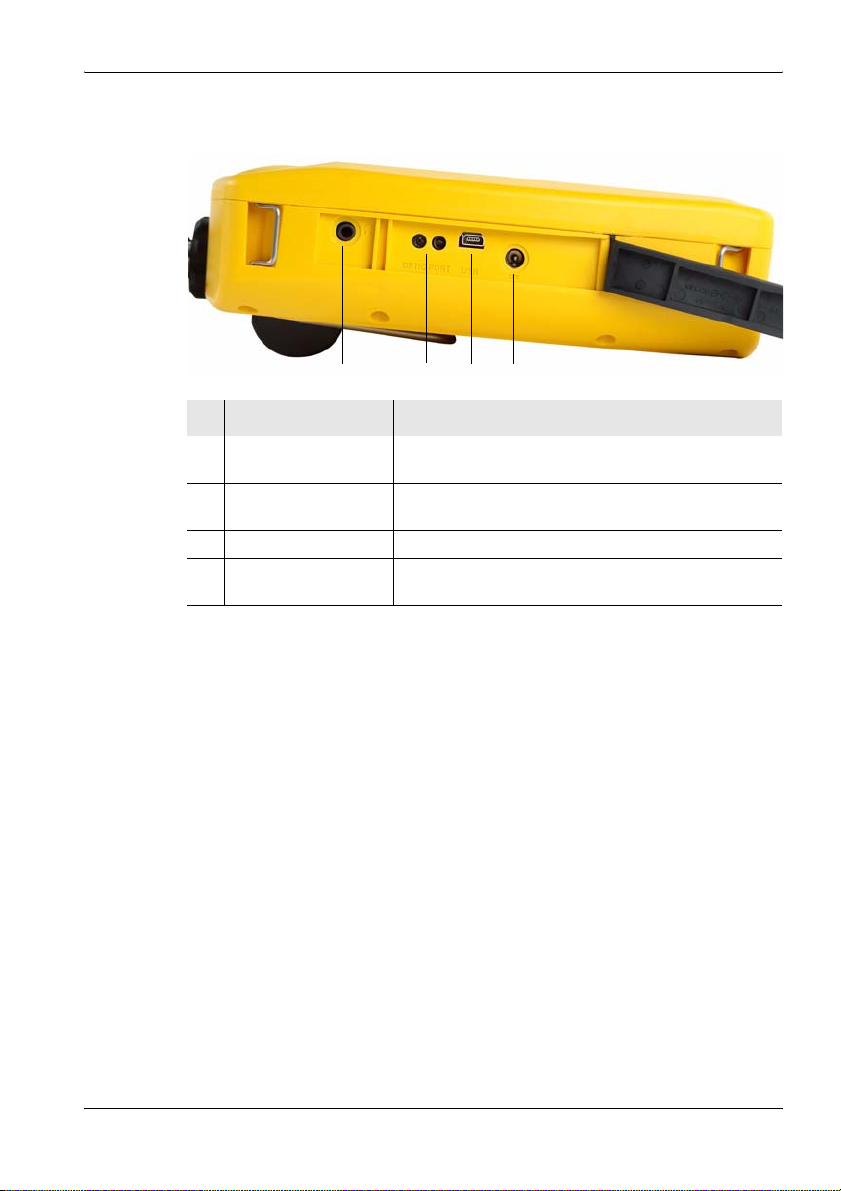
3.2.4 Device side panel with external connectors
1234
No. Element Function / Description
1 Earphone socket For connecting an earphone for listening to saved
2 Optical connector For connecting optical cables for on-site device
3 USB, Mini-B type For connection to a computer (PC).
4 Charging socket For connecting to an external AC adapter / charger
voice comments.
communications
(nominal voltage: 9 V)
3.3 Power supply
The power supply is normally taken from the rechargeable battery pack
provided. It is also possible to use the AC adapter / charger supplied with
the device as a power source.
Narda SRM-3006 27
Page 40
3 Connecting Up and Starting to Use the Device
3.3.1 Operation from battery pack
A fully charged battery pack is sufficient for about 2.5 hours of operation
(with GPS and display backlight). This operating time can be increased
significantly by using the energy saving options (Power Save) such as
automatic backlight switch off (Backlight switches off after). The battery
pack is supplied in a pre-charged state and must be fully charged before
being used for the first time.
Note: Only use the original battery packs supplied with the device. If the
capacity of these battery packs is insufficient for your needs,
additional battery packs can be obtained as accessories.
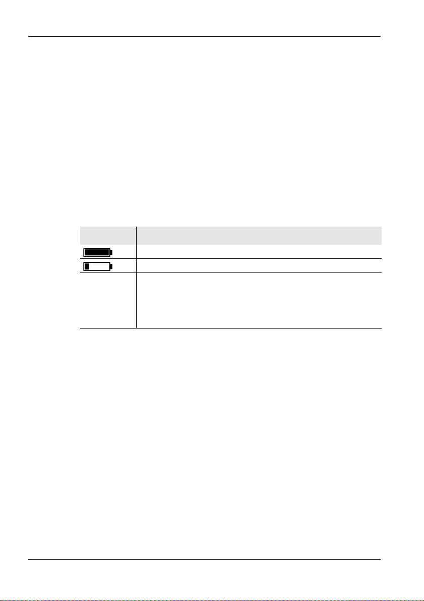
Charge indicator
The charge state of the battery pack is shown in the upper status line.
Display Meaning
The battery is fully charged.
The battery is almost discharged.
Batt. flashes The battery charge state is critical.
You should now switch the device off or connect it to the AC adapter
/ charger. If you continue to operate the device from the batteries, it
will switch off automatically after a short time. The device
configuration will however be saved before it switches off.
Charging the battery pack
A complete recharge takes about 4.5 hours.
You must use the AC adapter / charger provided or the optionally available
charging tray to recharge the battery pack.
Starting the charge cycle
✓ The AC line voltage must be the same as the operating voltage of the AC
adapter / charger.
1. Connect the AC adapter / charger to the charge socket of the SRM-3006.
2. Connect the AC adapter / charger to the AC line.
ª The charge cycle starts.
ª The Charge LED glows red during the charge cycle.
ª The AC adapter / charger switches to trickle charge mode
automatically and the Charge LED glows green when the charge
cycle is completed.
28 SRM-3006 Narda
Page 41
3.3.2 Handling battery packs
• Do not drop, damage, or disassemble the battery packs.
• Only recharge the battery packs in the way described in this operating
manual.
• Do not expose the battery packs to very high temperatures for an
extended period of time either separately or inside the device.
• Do not leave discharged battery packs in the device for an extended
period of time.
• Do not store the battery packs for longer than six months without
recharging them in the meantime.
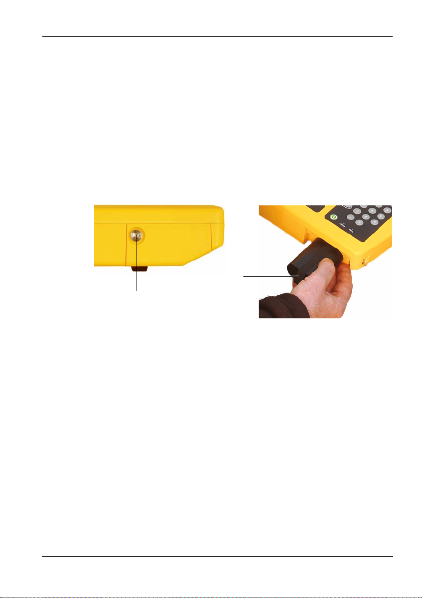
Replacing the battery pack:
1
1. Undo the fixing screw (1) in the lid of the battery compartment.
2. Pull out the battery pack using the tab (2).
3. Hold the tab on the new battery pack and slide the battery pack into the
compartment.
4. Replace the lid of the battery compartment and do up the fixing screw
(finger tight).
2
Note: If the old battery pack is no longer required, do not simply throw it
away with the normal trash. Dispose of it according to the regulations
applicable in the country of use (also refer to Proper disposal
on page 22).
Narda SRM-3006 29
Page 42

3 Connecting Up and Starting to Use the Device
3.3.3 Operation from AC adapter / charger
The SRM-3006 can also be operated and powered from the AC adapter /
charger.
However, this is not recommended for general use, as the measurement
characteristics can be significantly affected by the presence of the power
supply cable in the electromagnetic field when the SRM-3006 is operated
with the AC adapter / charger connected to it.
3.4 Fitting the antenna
This section describes the facilities and requirements for connecting an
antenna to the SRM-3006.
3.4.1 Fitting a Narda antenna directly on the Basic Unit
✓ The SRM-3006 is switched off.
1. Stand the Basic Unit up in a vertical position.
2. Place the N connector of the antenna on to the N connector of the Basic
Unit.
3. Screw the coupling nut of the antenna N connector slowly on to the Basic
Unit N connector taking care not to cross-thread it.
Note: If the coupling nut does not turn easily, reposition it and start again.
Approximately 4 full turns are needed to fully tighten the connection.
4. Place the control cable plug of the cable on to the multipin connector on
the Basic Unit so that the red mark on the control cable plug is aligned
with the notch in the multipin connector.
5. Push the control cable plug into the connector using the locking sleeve
until the plug lock engages.
ª The Narda antenna is connected.
The device automatically recognizes the antenna type that is connected.
This information is shown in the display in the general device configuration
section while the device is switched on.
30 SRM-3006 Narda
Page 43
3 Connecting Up and Starting to Use the Device
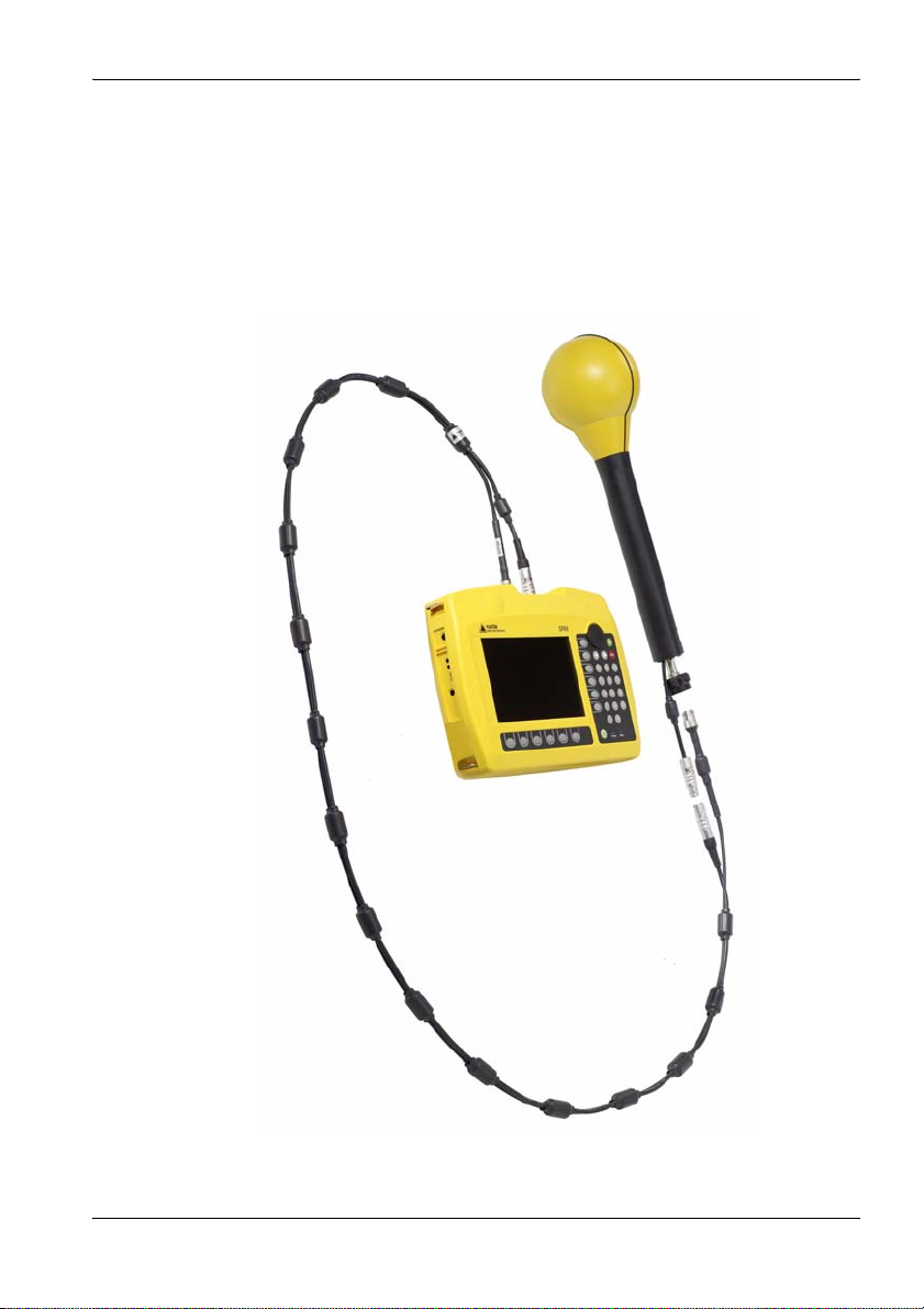
3.4.2 Connecting a Narda antenna to the Basic Unit using a Narda cable
The connection is made in two stages:
1. Connecting the Narda cable to the SRM-3006 (page 32)
2. Connecting the Narda cable to the Narda antenna (page 32)
Figure 3: Connecting the SRM-3006 to an antenna using a cable.
Narda SRM-3006 31
Page 44

3 Connecting Up and Starting to Use the Device
Connecting the Narda cable to the SRM-3006
✓ The SRM-3006 is switched off.
1. Stand the Basic Unit up in a vertical position.
2. Place the N connector of the cable on to the N connector of the Basic
Unit.
3. Screw the coupling nut of the cable N connector slowly on to the Basic
Unit N connector taking care not to cross-thread it.
Note: If the coupling nut does not turn easily, reposition it and start again.
Approximately 4 full turns are needed to fully tighten the connection.
4. Place the control cable plug of the cable on to the multipin connector on
the Basic Unit so that the red dot on the control cable plug is aligned with
the red dot on the multipin connector.
5. Push the control cable plug into the connector using the locking sleeve
until the plug lock engages.
ª The Narda cable is connected.
The device automatically recognizes the cable type that is connected.
This information is shown in the display in the general device
configuration section while the device is switched on.
Connecting the Narda cable to the Narda antenna
✓ The SRM-3006 is switched off.
1. Place the N connector of the cable on to the N connector of the antenna.
2. Screw the coupling nut of the cable N connector slowly on to the antenna
N connector taking care not to cross-thread it.
Note: If the coupling nut does not turn easily, reposition it and start again.
Approximately 4 full turns are needed to fully tighten the connection.
3. Place the control cable connector of the cable on to the control cable
connector of the antenna so that the red dot on the control cable
connector is aligned with the red dot on the antenna control cable
connector.
4. Push the antenna control cable plug into the connector using the locking
sleeve until the plug lock engages.
ª The Narda antenna is connected.
The device automatically recognizes the antenna type that is
connected. This information is shown in the display in the general
device configuration section while the device is switched on.
32 SRM-3006 Narda
Page 45

3 Connecting Up and Starting to Use the Device
3.4.3 Using commercially-available cables and antennas
Automatic recognition of the cable or antenna type that is connected is not
possible if third party products (commercially available cables and
antennas) are used instead of Narda components.
This means that when other cables are used the cable loss will not be taken
into account, and the results will not be shown in units of field strength or as
a percentage of the selected human safety standard limit value if other
antennas are used.
Note: The data for the connected cable and antennas must be entered in
the SRM-3006 manually using the PC software if third party products
are used (see description below).
Manually entering the data for third party components
The data must first be entered in the PC software, after which they can be
uploaded to the SRM-3006.
To enter the data:
1. Enter the data from the calibration report for the third party components
into the PC software (refer to the PC software online help for details).
2. Save the created configuration on the PC.
3. Upload the configuration data to the SRM-3006.
4. Select the cable and / or antenna on the SRM-3006.
3.4.4 Fitting a Narda antenna on a tripod
Special devices are needed for attaching the Narda antennas to a tripod.
Two types of antenna holder are available from Narda for this purpose.
Antenna holder for three axis antennas
This antenna holder can be attached to the tripod to allow vertical or
horizontal alignment of the antenna. Because the antenna is non-directional
(three axis) the alignment should not influence the result in any way.
Nevertheless, it is a good idea to align the antenna head roughly in the
(presumed) direction of the field source in order to minimize any side effects.
Narda SRM-3006 33
Page 46

3 Connecting Up and Starting to Use the Device
Assembly
1. Screw the antenna holder vertically or horizontally on to the tripod.
2. Attach the antenna to the holder using the Velcro strips.
3. Connect the antenna and the Basic Unit together using a cable (see
Connecting a Narda antenna to the Basic Unit using a Narda cable
on page 31).
Figure 4: Antenna attached to the antenna holder for three axis (isotropic)
antennas (3501⁄90.02), assembled horizontally (left) and vertically (right)
Antenna holder for single axis and three axis antennas
This antenna holder aligns the antenna in precisely defined positions.
This covers two applications:
• Single axis antennas can be simply rotated into three mutually
perpendicular (orthogonal) positions in order to perform isotropic
measurements.
• Three axis (isotropic) antennas can be precisely aligned in order to
measure a specific single axis.
34 SRM-3006 Narda
Page 47

Assembly
3 Connecting Up and Starting to Use the Device
Figure 5: Single axis E-field antenna (top) and single axis H-field antenna (bottom),
fitted on the antenna holder for single axis and three axis
antennas (3501⁄90.01)
Narda SRM-3006 35
Page 48
3 Connecting Up and Starting to Use the Device
1. Screw the antenna holder plate on to the tripod.
2. Screw the antenna holder on to the antenna holder plate.
3. Undo the Velcro strips and place the antenna in the holder so that the N
connector and the control cable fit into the guideway (see Figure 6 on
page 37).
4. Do up the Velcro strips.
5. Turn the antenna to the desired position (marked on the antenna holder)
and do up the screw to fix it in position.
6. Connect the antenna and the Basic Unit together using a cable (see
Connecting a Narda antenna to the Basic Unit using a Narda cable
on page 31).
NOTICE
Damage caused by spacing screws
The black coating can be damaged by the spacing screws.
⇒ When removing the antenna from the holder, slide it up in the direction
of the antenna head first before removing it from the holder.
36 SRM-3006 Narda
Page 49

3 Connecting Up and Starting to Use the Device
Figure 6: Cable and N connector in guideway
Narda SRM-3006 37
Page 50

3 Connecting Up and Starting to Use the Device
38 SRM-3006 Narda
Page 51

4 Operation and Basic Settings
4 Operation and
Basic Settings
This chapter describes the controls and connectors on the device.
4.1 Controls (page 40)
4.2 Switching the device on and off (page 41)
4.3 LCD screen elements (page 42)
4.4 Fundamental operating steps (page 46)
Narda SRM-3006 39
Page 52
4 Operation and Basic Settings
4.1 Controls
The following controls are provided for operating the SRM-3006:
• Rotary control
• Hardware keys (referred to as keys in this manual)
• Software keys (referred to as softkeys in this manual)
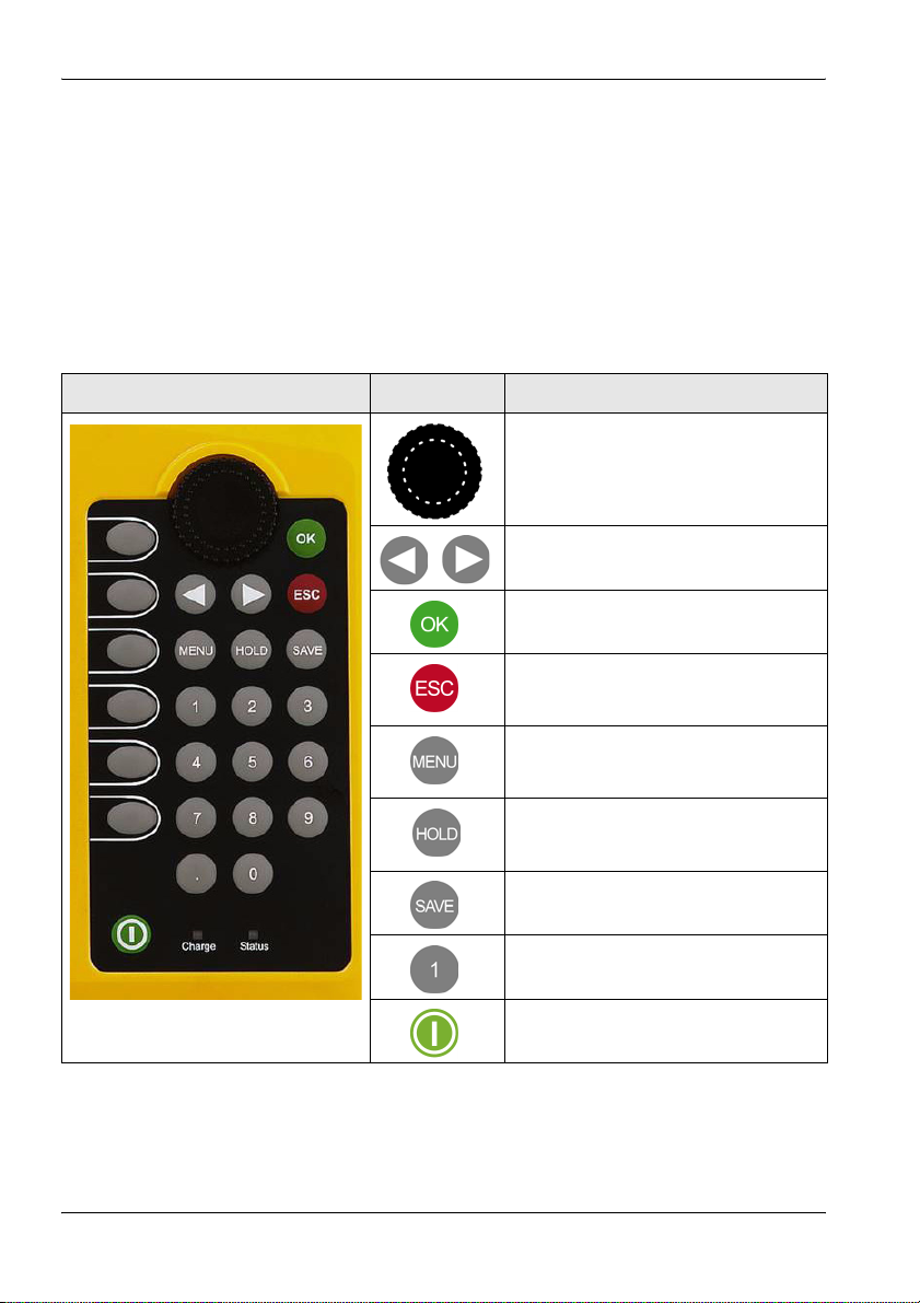
4.1.1 Rotary control and keys
Element Function / Description
Selects functions and values.
Moves to the left or right in entry boxes.
Confirms changes in settings.
• Cancels the current operating step;
changes in values are not made.
• Returns to the next higher menu level.
Opens the main menu for selecting
operating modes and changing system
and device settings.
Freezes the display; the measurement
continues. Press again to update the
display to show the actual values again.
Saves the data in the data logger.
For entering numbers and the decimal
point.
Switches the device on and off (hold
down key).
40 SRM-3006 Narda
Page 53

4 Operation and Basic Settings
4.1.2 Softkeys
The softkey functions depend on the selected menu level, operating mode,
or function. The softkeys are therefore described in the menu and operating
mode descriptions.
4.2 Switching the device on and off
Switching on
⇒ Press and hold down the ON/OFF key for a few seconds.
ª The device switches on.
You can terminate the switch on process by pressing the Quit softkey.
The device performs a self test during the boot up process. The results are
displayed on the screen.
The screen displayed after switch on depends on the setting of the Power
on function. For more information about this, see Changing the switch on
behavior on page 68.
Switching off
⇒ Press and hold down the ON/OFF key for a few seconds.
ª The device switches off.
Narda SRM-3006 41
Page 54

4 Operation and Basic Settings
4.3 LCD screen elements
1
2
3
4
5
6
Figure 7: LCD screen
Table 2: LCD screen elements
7
No. Element Description
1 Upper status bar Indicates general parameter settings.
2 Navigation bar Shows information about the selected function.
3 Display area Graphical or numerical display of measurement
4 Info bar • Shows menu path to the current function.
5 Lower status bar Indicates settings and process analysis; displays error
6 Horizontal softkeys Displayed functions are context-sensitive.
7 Vertical softkeys Displayed functions are context-sensitive.
values.
• Shows text entered by the user
(for measurement routines, entry from PC only).
• Indication of corrected parameters.
messages.
42 SRM-3006 Narda
Page 55
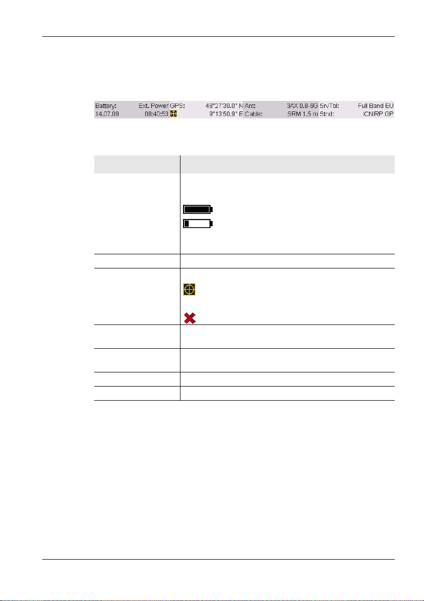
4.3.1 The upper status bar
The upper status bar gives information about the device, the components
used, and the general settings.
Figure 8: Upper status bar
Table 3: Upper status bar elements
Element Description
Battery Power supply indicator:
Ext. Power External supply from AC adapter.
Batt.
(flashes)
Date, time Indicates the date and time.
GPS GPS receiver status and coordinates:
Coordinates GPS reception, coordinates are displayed
Ant. Antenna used (displayed only if the type is automatically
recognized or has been entered manually).
Cable Cable used (displayed only if the type is automatically
recognized or has been entered manually).
Service Table Selected service table.
Standard Selected measurement standard.
4 Operation and Basic Settings
Battery fully charged.
Battery almost discharged.
Battery discharged, device powers down
immediately and switches off.
DGPS reception.
No GPS reception.
Narda SRM-3006 43
Page 56

4 Operation and Basic Settings
4.3.2 The lower status bar
The lower status bar gives information about the current measurement. The
contents of the display may vary, depending on the operating mode.
Figure 9: Lower status bar
Table 4: Lower status bar elements
Element Description
MR Measurement range.
RBW Resolution bandwidth.
Others Field strengths outside the selected services.
Sweep Time Duration of each measurement cycle.
Progress Measurement progress (checks the progress of processor-
No. of Runs Number of measurements made since the measurement
AVG Number of measurements used to form the average or time
intensive measurements until the first results are displayed
on the screen)
was last started.
for average formation.
44 SRM-3006 Narda
Page 57

4.3.3 The navigator bar
The screen displays various elements that make navigation easier and
which give you information about the actual position in the menu and the
selected function.
The actual display mode selection is shown at the left hand edge of the
navigation bar.
Arrow symbols at the right hand edge of the bar indicate further information
which can be displayed by pressing the arrow keys or by turning the rotary
control:
Symbol Meaning
Pressing the key displays further information (e.g. in a column of the
table).
Pressing the key displays further information (e.g. in a column of the
table).
Pressing the key as well as the key displays further information.
Paging up by turning the rotary control displays further information (e.g.
lines in the table).
Paging down by turning the rotary control displays further information
(e.g. lines in the table).
Paging up or down by turning the rotary control displays further
information (e.g. lines in the table).
4 Operation and Basic Settings
4.3.4 Activating / deactivating status and info bars
The upper status bar, help bar and lower status bar can be individually
activated or deactivated. If you do not need the information that is displayed
in these bars, you can deactivate all of them to maximize the area of the
screen that is available to display the measurement values.
To change the screen arrangement:
✓ You have selected an operating mode.
1. Press the Display softkey.
2. Press the Screen Arrangement softkey.
3. Use the rotary control and softkeys to select the settings you want and
then press the OK key to implement the changes.
Narda SRM-3006 45
Page 58
4 Operation and Basic Settings
4.4 Fundamental operating steps
The operating steps described in this section are repeated in every menu
and function. They are therefore described only once here. In all
subsequent descriptions of operating modes, it is assumed that you are
familiar with these fundamental steps.
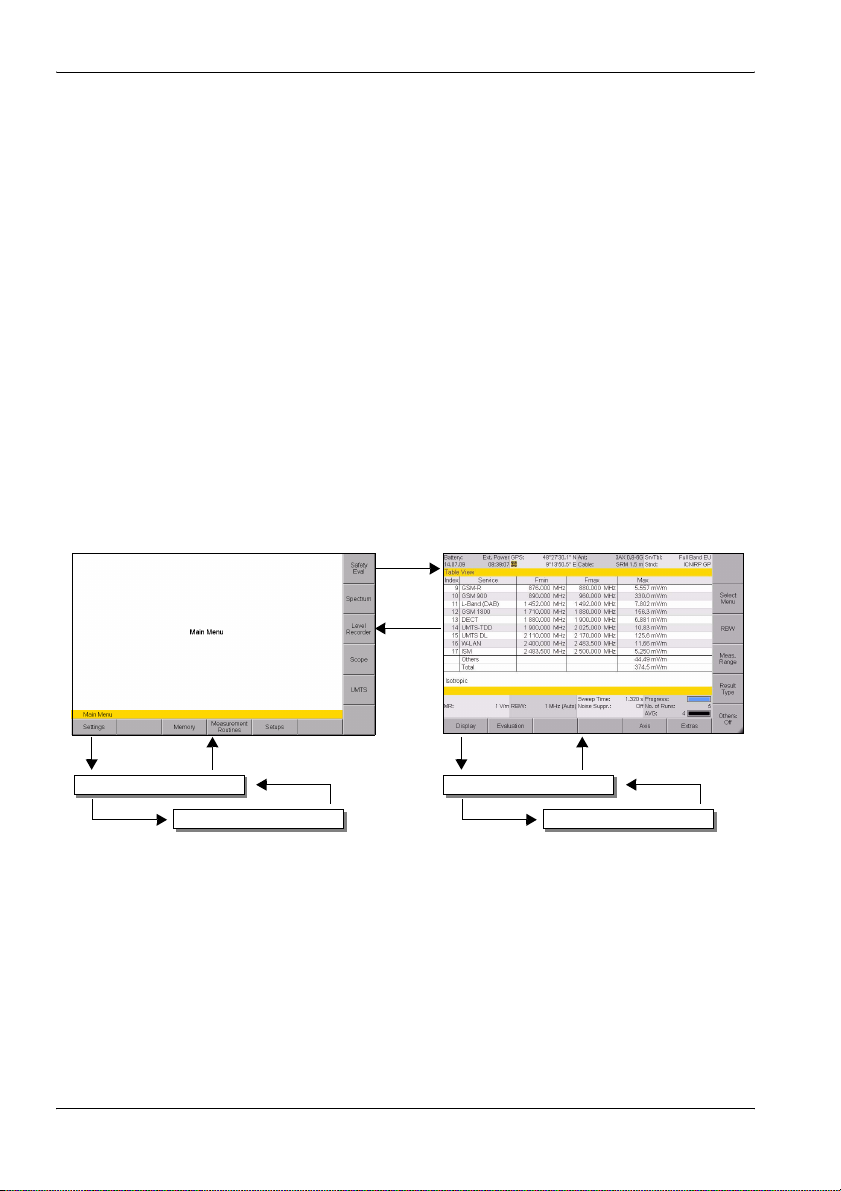
4.4.1 Navigating in the menus
The operating modes and functions of the SRM-3006 are arranged in
hierarchical menu levels. The diagram below (see Figure 10 on page 46)
shows this arrangement using the main menu and some of the functions in
Safety Eval (Safety Evaluation) mode as examples.
To navigate in the menus:
• To move down one level: Press the appropriate Softkey.
• To move up one level: Press the ESC key.
• To return to the measurement or the main menu: Press the MENU key.
Softkey
Menu
MenuSoftkey
Settings
Softkey
Figure 10: Examples showing how the menus and functions are arranged.
Service Tables
ESC
Evaluation
Softkey
ESCSoftkey
ESC
Distribution
46 SRM-3006 Narda
Page 59
4 Operation and Basic Settings
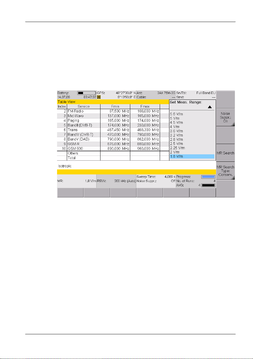
4.4.2 Selecting entries from a list
Settings are often made by selecting entries or items from a list.
Simple list
You can only select a single item from a simple list. This is demonstrated by
the selection of a measurement range (Meas. Range) in the example
below.
Figure 11: Example of a simple list: Select Meas Range
To select an item:
1. Use the rotary control to highlight the desired item.
2. Press the OK key to confirm your selection.
ª The new value is set.
Narda SRM-3006 47
Page 60

4 Operation and Basic Settings
Extended list
You can select more than one entry or item from an extended list. You can
select one item at a time or use the softkeys to select all the items. This is
demonstrated by the selection of services (Select Services) in the example
below.
Figure 12: Example of an extended list: Select menu
A selection box indicates if the option has been selected or not in an
extended list.
To select or deselect items individually using the rotary control:
1. Use the rotary control to highlight the desired item.
2. Press the Select Deselect key to select or deselect the item.
ª The selection box shows the actual status.
3. Press the OK key to return to the measurement display.
To select or deselect several items at the same time:
Use the following softkeys, to select or deselect all the items or a group of
items in a list.
Note: The softkeys that are actually available depend on the Select menu
that is opened.
⇒ When you have selected the items you want, press the OK key to revert
to the measurement display again.
48 SRM-3006 Narda
Page 61

Select Deselect All
• If all the items were selected, they will all be deselected.
• If all the items were deselected, they will all be selected.
• If some items were selected and others deselected, they will all be
selected or deselected.
Invert Selection
Changes the status of every item in the list.
Select First / Select Last
You can use these softkeys to select a group of items from the list.
1. First deselect all items using the Select Deselect All softkey.
2. Use the rotary control to highlight the first item in the group that you want
to select and then press the Select First softkey.
3. Use the rotary control to highlight the last item in the group that you want
to select and then press the Select Last softkey.
4. The highlighted section is now selected.
4.4.3 Changing numerical values
You can change numerical values using the rotary control or by using the
keys.
Note: If you use the rotary control to change a numerical value, you cannot
then use the keys to change the value or vice versa in the same
setting step. To change from one control to the other, you must first
exit the Select menu and then open it again.
To change a value using the rotary control:
1. Open the Select menu.
2. Use the arrow keys to select the digit you want to change and
then use the rotary control to set the desired value.
3. Press the OK key to set the new value.
To change a value using the keys:
1. Open the Select menu.
2. Use the number keys and decimal point key to enter the desired value
and enter the desired units using the appropriate softkey. (You can
delete digits using the Backspace softkey.)
ª The new value is set and the Select menu closes as soon as you have
entered the units.
Narda SRM-3006 49
Page 62
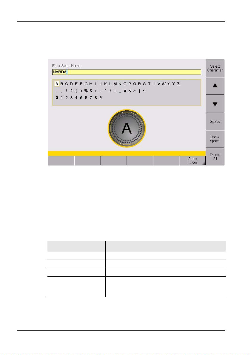
4 Operation and Basic Settings
4.4.4 Entering text
A simple text editor opens so that you can enter alphanumeric characters
(e.g. when saving setups):
Figure 13: Text editor for entering alphanumeric characters
To enter text:
1. Use the rotary control to select a character from the character field.
(You can select a line directly using the ▲ and ▼ softkeys.)
ª The selected character is marked by a circle.
2. Press the Select Character to enter the character.
3. Press the OK key when you have finished entering the characters you
want.
There are some further functions that you can use to enter text:
Softkey Function
Space Enters a space.
Backspace Deletes the last character entered.
Delete All Deletes all characters entered.
Case Switches between upper and lower case characters:
• Lower: lower case characters.
• Upper: upper case characters.
50 SRM-3006 Narda
Page 63

4 Operation and Basic Settings
4.4.5 Softkeys with toggle function
A black marked right lower corner indicates a toggle
function.
The displayed function is the one that can be selected.
In this example: Others = On, pressing the softkey will set
Other to Off.
4.4.6 Creating a screenshot
You can download the saved screenshots in PNG format from the device
using the SRM-3006 PC software applications SRM-3006 Tools.
To create a screenshot:
1. Press the Display softkey.
2. Press the Save Screenshot softkey.
Narda SRM-3006 51
Page 64

4 Operation and Basic Settings
52 SRM-3006 Narda
Page 65

5 The Main Menu
This chapter describes all the Main Menu with all the settings that apply to
the device itself and to the components connected to it. Furthermore you will
find here how to use the memory, to run measurement routines and to use
setups.
5.1 Overview of functions and operating modes (page 54)
5.2 Display and editing device and component settings (page 55)
5.3 The memory menu (page 64)
5.4 Using measurement routines (page 65)
5.5 Saving and loading setups (page 66)
5 The Main Menu
Narda SRM-3006 53
Page 66
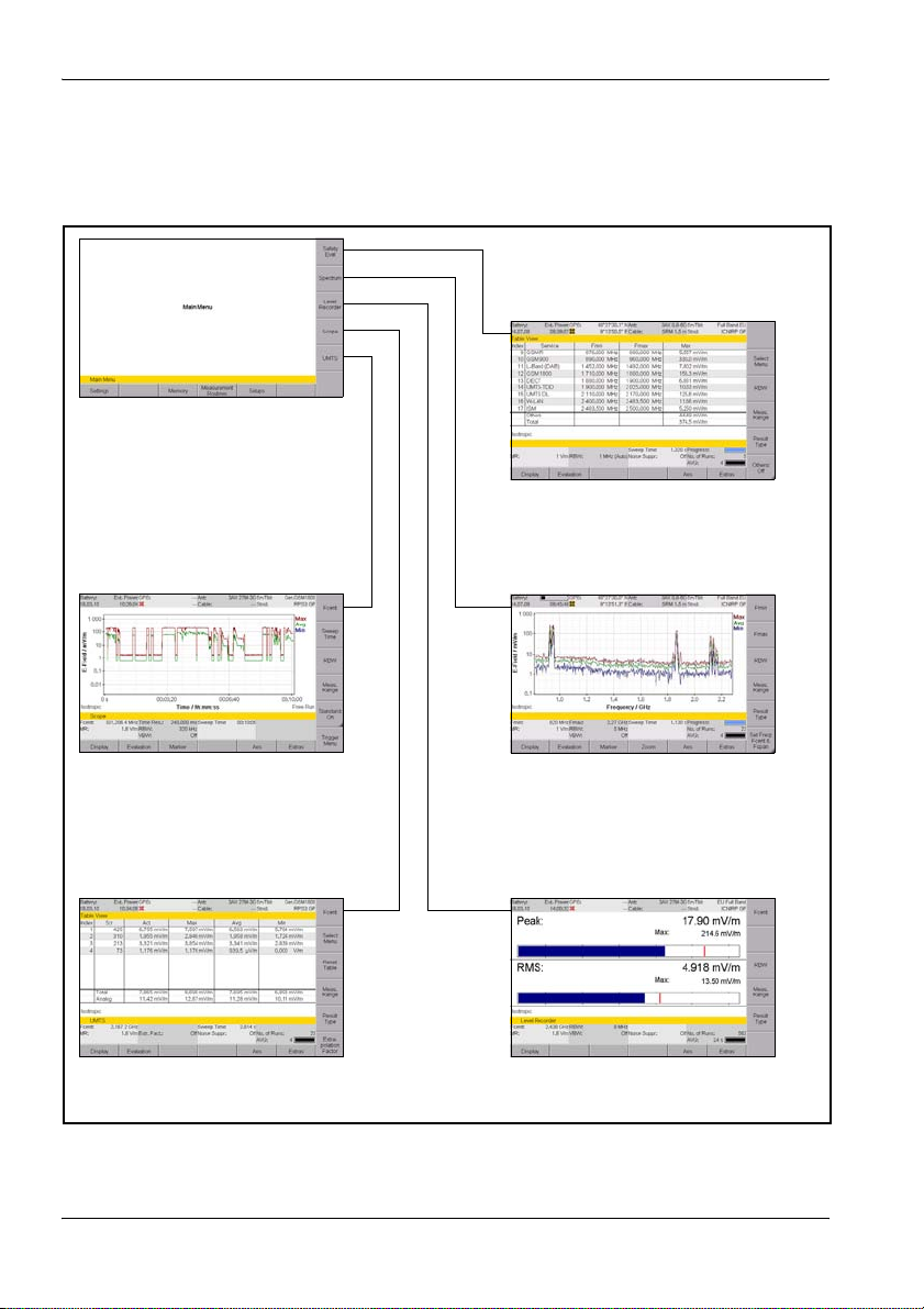
5 The Main Menu
5.1 Overview of functions and operating modes
• Settings:
– Device settings
– Antenna, Cable, Service Tables,
Standards
• Memory management
• Measurement routines
• Setups
• Rapid overview of field situation
(graphical or as a table)
• Overall distribution
Safety EvaluationSpectrum Analysis
• Real time
• Long-term measurement
UMTS Scope
• Demodulation
Figure 14: Overview of operating modes and functions.
• Details of field situation
(graphical or as a table)
• Peak values (table)
• Wideband values (integrated/
channel power measurement)
Level Recorder
• Rapid level measurement also
suitable for pulsed signals
54 SRM-3006 Narda
Page 67
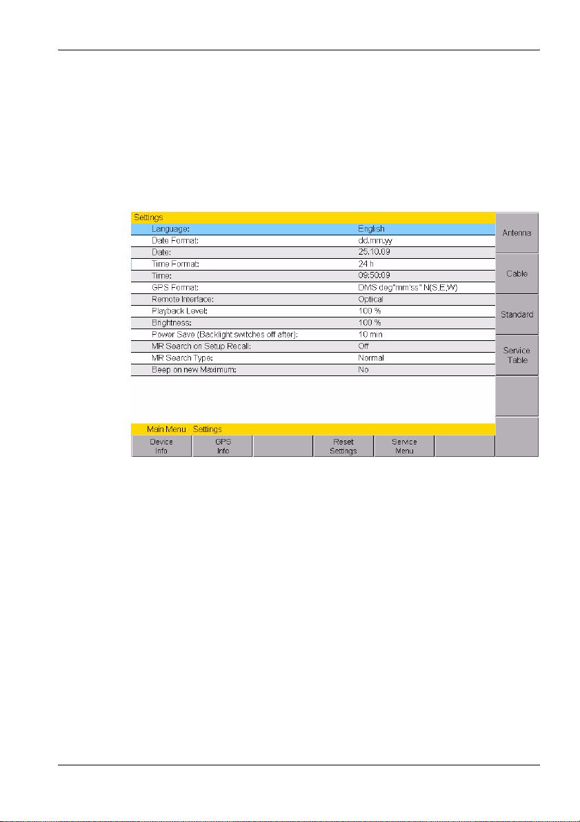
5.2 Display and editing device and component settings
Main Menu • Settings
The Settings menu contains all the settings for the device, the connected
antenna and cable, the applied measurement standard and the selected
service table.
5 The Main Menu
Figure 15: Settings menu
All device specific settings can be edited immediately by selecting an entry
from the list using the rotary control. All other settings (e.g. antennas,
cables, etc.) can be reached by means of the softkeys on the right side.
This menu allows you to perform the following actions:
• Changing the language, date, and time (page 56)
• Editing device-specific settings (page 57)
• Displaying device information (page 58)
• Displaying GPS information (page 59)
• Resetting all device settings (page 59)
• Performing device diagnosis (page 60)
• Displaying and selecting the available antennas (page 61)
• Displaying and selecting the available cables (page 61)
• Displaying and selecting the safety standards (page 62)
• Displaying and creating service tables (page 62)
Narda SRM-3006 55
Page 68
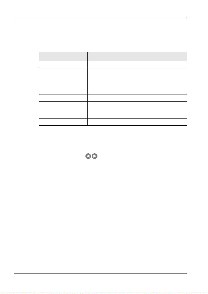
5 The Main Menu
5.2.1 Changing the language, date, and time
Main Menu • Settings
Table 5: Descriptions of Device Settings
Item Description and available options
Language User interface language
Date Format Date format:
• yy.mm.dd (year.month.day)
• yy-mm-dd (year-month-day)
• mm/dd/yy (day/month/year)
• dd.mm.yy (day.month.year)
Date Date
Time Format Time format:
• 12 h (12-hour clock)
• 24 h (24-hour clock)
Time Time (hour:minute:second)
To change the settings:
1. Use the rotary control to highlight the item and select it by pressing OK.
2. Use the rotary control to change the setting and press OK to confirm the
change or press ESC to cancel the changes.
Use the arrow keys to move the cursor by one digit.
3. Press ESC to return to the Main menu.
56 SRM-3006 Narda
Page 69

5.2.2 Editing device-specific settings
Main Menu • Settings
Table 6: Description of device-specific settings
Item Description and available options
GPS Format GPS data display format:
• DegDec (-)ddd.ddddd
• MinDec (-)ddd°mm.mmm
• DMS deg°mm’ss” N(S,E,W)
Remote Interface Interface used for remote control:
• Optical
•USB
Playback Level Earphone playback volume control:
• In steps from 1% to 100%
Brightness LCD screen brightness
• In steps from 1% to 100%
Power Save (Backlight
switches off after):
MR Search on Setup
Recall
MR Search Type Measurement range search type:
Beep on new
Maximum
Power save mode, backlight switches off automatically:
• In steps from 1 min. to 30 min
• On permanently
Search for measurement range when a setup is recalled:
•On
•Off
• Normal: The measurement range is selected so that no
saturation occurs in a normal environment.
• Conservative: The measurement range is selected so
that no saturation occurs even in an environment with
extremely variable signal strengths (multi-frequency
environment).
Beep when new maximum detected:
•Yes
•No
5 The Main Menu
To change the settings:
1. Use the rotary control to highlight the item and select it by pressing OK.
2. Use the rotary control to change the setting and press OK to confirm the
change or press ESC to cancel the changes.
3. Press ESC to return to the Main menu.
Narda SRM-3006 57
Page 70
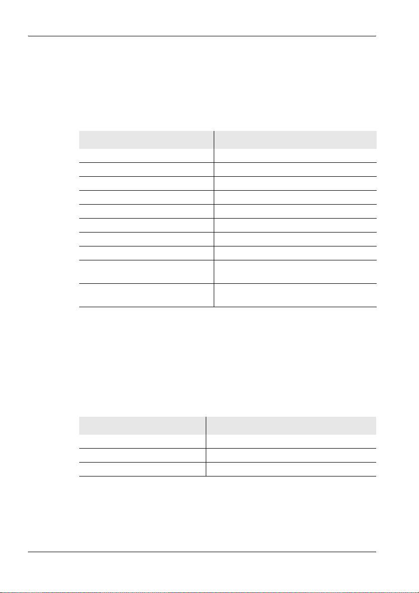
5 The Main Menu
5.2.3 Displaying device information
Main Menu • Settings • Device Info
⇒ Press the Device Info softkey.
ª A list of the device information is displayed.
Table 7: Description of Device Info list
Information Description
Device Model Device model name
Production ID Production number
Serial Number Device serial number
ID Number Unique device identification number
Firmware Version Device software version
Firmware Date Device software date
Calibration Date Date of last calibration
Next Recommended Calibration Date recommended for next calibration
UMTS C-CPICH Demodulation UMTS option status
Scope Scope option status
(activated / deactivated)
(activated / deactivated)
Displaying connected antenna information
Main Menu • Settings • Device Info • Antenna Info
Note: Information about the connected antenna is only displayed when you
use a Narda antenna.
⇒ Press the Antenna Info softkey.
ª The antenna information is displayed as a list.
Table 8: Description of Antenna Info list
Information Description
Long Name Antenna description
Serial Number Antenna serial number
Calibration Date Date of last calibration
58 SRM-3006 Narda
Page 71

Displaying connected cable information
Main Menu • Settings • Device Info • Cable Info
Note: Information about the connected cable is only displayed when you
use a Narda cable.
⇒ Press the Cable Info softkey.
ª The cable information is displayed as a list.
Table 9: Description of Cable Info list
Information Description
Long Name Cable description
Serial Number Cable serial number
Calibration Date Date of last calibration
5.2.4 Displaying GPS information
Main Menu • Settings • GPS Info
⇒ Press the GPS Info softkey.
ª A list of the GPS information is displayed.
i
Table 10: Description of GPS Info list
5 The Main Menu
Information Description
Satellites in Use Number of satellites received
GPS Quality Indicator • NO = no GPS reception
• GPS = standard GPS
• DGPS = differential GPS with better
accuracy than GPS
Latitude Latitude of actual position
Longitude Longitude of actual position
Altitude Altitude of actual position
UTC Time Universal Time Coordinate
5.2.5 Resetting all device settings
Main Menu • Settings • Reset Settings
⇒ Press the Reset Settings softkey.
ª The device settings shown in the window are all reset to their factory
default settings.
Narda SRM-3006 59
Page 72

5 The Main Menu
To reset all device settings:
1. Open the Service menu (Main Menu • Settings • Service Menu) and
press the Factory Settings softkey.
2. Press OK to confirm the reset.
5.2.6 Performing device diagnosis
Main Menu • Settings • Service Menu
This menu allows you to check the display and to monitor some basic device
data.
⇒ Press the Service Menu softkey.
ª The Service Menu is displayed.
To check the display:
⇒ Press the Display Test softkey.
ª The basic colors red, green and blue are displayed in turn.
The test stops after three cycles.
⇒ Press the ESC key to end the test immediately.
To display the device diagnostics:
⇒ Press the Device Diag softkey.
ª A list of some basic data is displayed.
Note: The displayed data is intended primarily for servicing purposes.
Table 11: Description of Device Diagnostics list
Information Description
Mainboard Temperature Temperature of main circuit board
RFboard Temperature Temperature of RF circuit board
Battery Voltage Actual battery voltage
Battery Capacity Remaining battery capacity
Buffer Battery Voltage Internal buffer battery voltage
Free Memory Free memory space in megabytes, absolute
Free Memory in Percent Free memory space in percent, relative
Device Calibration OK Indicates whether device calibration is still valid or not
Operating Hours Counter Number of hours of operation so far
60 SRM-3006 Narda
Page 73

5 The Main Menu
5.2.7 Displaying and selecting the available antennas
Main Menu • Settings • Antenna
⇒ Press the Antenna softkey.
ª The available antennas are listed with their characteristic data.
The detected antenna type will be displayed when you use a Narda
antenna. You cannot change this setting.
n
Table 12: Description of Antennas list
Item Description
Short Name Short name for the antenna (shown on the screen)
Fmin Lower frequency limit
Fmax Upper frequency limit
Property Field type (E-field, H-field)
Cal. Date Date of last calibration
Note: The axis configuration can be selected in the measurement menus
using the Axis function according to the antenna type (single axis or
isotropic). See Selecting an axis mode on page 84.
5.2.8 Displaying and selecting the available cables
Main Menu • Settings • Cable
⇒ Press the Cable softkey.
ª The available cables are listed with their characteristic data.
Table 13: Description of Cables list
Item Description
Short Name Short name for the cable (shown on the screen)
Fmin Lower frequency limit
Fmax Upper frequency limit
Cal. Date Date of last calibration
You can still select a different cable even if the cable connected is detected
automatically. This manual selection allows for the use of an attenuator, for
example.
To select a cable:
⇒ Use the rotary control to select an item and press OK to confirm the
selection.
Narda SRM-3006 61
Page 74
5 The Main Menu
5.2.9 Displaying and selecting the safety standards
Main Menu • Settings • Standard
⇒ Press the Standard softkey.
ª The available safety standards are listed.
Table 14: Description of Safety Standards list
Item Description
Short Name Short name for the standard (shown on the screen)
Long Name Full name of the standard (shown in the Select menu)
To select a standard:
⇒ Use the rotary control to select an item and press OK to confirm the
selection.
5.2.10 Displaying and creating service tables
Main Menu • Settings • Service Tables
⇒ Press the Service Tables softkey.
ª The available service tables are listed.
Table 15: Description of Service Tables list
Item Description
Short Name Short name for the service table (shown on the screen)
Long Name Full name of the service table (shown in the Select menu)
Note: Some service table items may not be available for selection because
of the antenna that is being used.
To select a service table:
⇒ Use the rotary control to select an item and press OK to confirm the
selection.
62 SRM-3006 Narda
Page 75

Displaying the services in a service table
Main Menu • Settings • Service Tables • View
⇒ Press the View softkey.
ª The services included in the table are listed.
Table 16: Description of Service Table ... list
Information Description
Service Service name
Fmin Lower frequency limit
Fmax Upper frequency limit
RBW Resolution bandwidth
Creating a new service table
Main Menu • Settings • Service Tables • Create
You can create a new service table using this menu.
Note: The facilities for creating service tables using the SRM-3006 itself
are limited. You cannot enter individual services manually or change
the service names. It is much more convenient to use the
SRM-3006 Tools PC software to create service tables. You can then
upload these service tables to the SRM-3006.
5 The Main Menu
To create a new service table:
1. Press the Create softkey and enter the desired values.
2. Press the Save Table softkey when you have entered all the values.
3. Enter a name for the service table and save it.
Narda SRM-3006 63
Page 76

5 The Main Menu
The example below shows the parameters for the GSM-900 service. The
corresponding entries in the service table are found in column 3 of Table 17
(the example values are shown in bold type).
Example: GSM-900
Downlink: 935.2 – 960 MHz
Channel number: 1 – 124
Channel width: 200 kHz
–> without gap
–> all channels have the same width
Table 17: Description of Create Service Table list
Item Description Entries for the
First Service Start Frequency Starting frequency for the service 935.3
First Service Channel Number First channel number in the service 1
Channel Step Width Channel bandwidth 200 kHz
Service Bandwidth Service bandwidth 200 kHz
Number of Services Number of services 124
Preferred RBW Preferred resolution bandwidth 50 kHz
example GSM-900P
(center frequency of
935.2 – 935.4 MHz
(200 kHz/4)
5.3 The memory menu
Main Menu • Memory
The following functions are contained in the Memory menu:
• Display data sets
• Display saved screenshots
• Conditional saving
• Timer controlled saving
• Set comment function
⇒ You can find detailed information about all these functions in chapter 13
Measurement Data Memory on page 157.
64 SRM-3006 Narda
Page 77

5.4 Using measurement routines
Main Menu • Measurement Routines
Measurement routines are automated sequences of setups. They are
particularly useful for the following applications:
• for eliminating errors when performing repetitive measurement tasks
• for ensuring compliance with company regulations for sequences /
procedures
• as a guide for semi-skilled staff.
Note: When you have saved setups on the device, you can create
measurement routines only with the aid of the PC software on a PC.
These routines must then be uploaded to the device. You can only
display and start the measurement routines on the device itself.
5.4.1 Displaying measurement routines
Main Menu • Measurement Routines • View Routine
⇒ Press the View Routine softkey.
ª A list of the setups contained in the routine and the sequence criteria
is displayed.
Table 18: Description of Measurement Routine ... list
5 The Main Menu
Item Description
Index Sequential index number
Setup Name Name of setup
Storing Condition Condition for storing the results
Time Measurement duration for timer controlled
No. of Runs Number of measurements for measurement
Auto Next Step Start next setup automatically (On, Off)
storing.
cycle controlled storing
Narda SRM-3006 65
Page 78

5 The Main Menu
5.4.2 Starting a measurement routine
Main Menu • Measurement Routines • Start Routine
⇒ Use the rotary control to highlight the desired measurement routine and
press the Start Routine softkey or press OK.
ª The measurement routine starts.
5.5 Saving and loading setups
Main Menu • Setups
You can use this menu to save all the settings as a setup or recall and load
setups that you have saved previously.
Note: Setups can only be created on the device itself. You cannot create
setups on a PC. In contrast, you can only delete setups using the PC
software. You cannot delete setups on the device itself.
5.5.1 Saving settings as a setup
Main Menu • Setups • Save Setup
1. Make the desired settings on the device.
2. Switch to the Main Menu • Setups menu and press the Save Setup
softkey.
ª The entry box opens.
Note: You can also save a setup directly from an operating mode. This
function is found in the Display menu of the operating mode.
3. Enter a suitable name and press OK to confirm your entry.
ª The settings are saved as a new setup and displayed in the overview
bar.
5.5.2 Loading settings from a setup
Main Menu • Setups • Recall Setup
⇒ Use the rotary control to highlight the desired setup and press the
Recall Setup softkey or the OK key.
ª The settings saved in the selected setup will be loaded and the
display switches to the measurement screen.
66 SRM-3006 Narda
Page 79

5.5.3 Editing the setup list
Main Menu • Setups
You can edit the setup list as well as save and recall setups.
Sorting the setup list
Main Menu • Setups • Sort
1. Press the Sort softkey.
2. Select sort by Name or Mode (operating mode) and press OK.
ª The list will be resorted according to the selected criterion.
Overwriting a setup
Main Menu • Setups • Overwrite Setup
1. Use the rotary control to highlight the setup to be overwritten and press
the Overwrite Setup softkey.
2. Confirm the action by pressing OK. (You can cancel the action by
pressing ESC.)
ª The settings in the existing setup will be overwritten with the actual
device settings.
5.5.4 Deleting setups
You cannot delete setups in the instrument itself. You can only delete them
using the PC software.
5 The Main Menu
Narda SRM-3006 67
Page 80

5 The Main Menu
5.5.5 Changing the switch on behavior
Main Menu • Setups • Power on
Main Menu • Setups • Mark Power on Setup
You can specify the settings to be used by the device when it starts up after
being switched on:
• Last Settings: The settings in use at the time the device was last
switched off will be used.
• Power On Setup: The setup marked in the Setups menu as the
Power on Setup will be used.
To start up using the settings last used:
⇒ Press the Power on softkey until Last Settings is shown (toggle
function).
ª The settings in use at the time the device was last switched off will be
used when it is next switched on.
To start up using a selected setup:
1. Press the Power on softkey until Power On Setup is shown (toggle
function).
2. Use the rotary control to highlight the desired setup and press the
Mark Power on Setup softkey.
ª The selected setup is marked in the list (‹‹...››) and will be loaded the
next time the device is switched on.
68 SRM-3006 Narda
Page 81

6 Functions Common to More Than One Operating Mode
6 Functions Common to
More Than One Operating
Mode
This chapter describes the functions that are common to more than one
operating mode. These functions are then indicated in the descriptions of
the individual operating modes by a cross reference to the relevant section
of this chapter.
6.1 Overview of functions common to more than one operating
mode (page 70)
6.2 Setting the resolution bandwidth (RBW) (page 71)
6.3 Setting the measurement range (Meas. Range) (page 72)
6.4 Selecting the result type (Result Type) (page 75)
6.5 The Marker function (page 77)
6.6 Selecting an axis mode (page 84)
6.7 Adjusting the Y axis (page 88)
6.8 Changing the displayed units (page 89)
6.9 Noise suppression (Noise Thresh.) (page 90)
6.10 Measuring spatial average values (Spatial AVG) (page 91)
6.11 Changing operating mode and keeping the same parameters
(page 91)
6.12 Useful shortcuts (page 92)
Narda SRM-3006 69
Page 82

6 Functions Common to More Than One Operating Mode
6.1 Overview of functions common to more than one operating mode
The table below indicates the operating modes that use the functions
described in this chapter.
Table 19: Functions and operating modes
Function
Resolution bandwidth (RBW)
Video bandwidth (VBW)
Meas. Range xxxxx
Result type xx(x)xx
Marker x
Axis xxxxx
Y- S c a l e x
Unit xxxxx
Noise Thresh. x–xx–
Spatial AVG xxx––
x = identical in all these modes, described in this chapter
(x) = present but not identical (description given in the chapter covering the operating mode)
– = not present in this operating mode
1) Fixed at 3.84 MHz
2) Act or Max/Avg/Min selected automatically depending on the settings
3) For Bargraph only
Safety
Evaluation
(x) x x –
Spectrum Level
3)
3)
Recorder
x––x
xx–x
UMTS Scope
1)
x
2)
The menu paths shown in gray immediately below the section heading
indicate the operating modes and sub-menus where the function described
can be found.
Screenshots, where used, only serve to illustrate the function. As a rule, the
settings described apply in the same way in the other operating modes
although the display on the screen may not be the same as the screenshot
used in this manual.
70 SRM-3006 Narda
Page 83

6 Functions Common to More Than One Operating Mode
6.2 Setting the resolution bandwidth (RBW)
Spectrum Analysis • RBW
Level Recorder • RBW
Scope • RBW
The resolution bandwidth (RBW) determines the characteristics of the
spectrum analyzer with regard to its ability to distinguish between signals
having the same amplitude. but different frequencies. Only signals having a
frequency spacing that is greater than the defined resolution bandwidth can
be distinguished from one another.
Background information:
The RBW selected for measuring signals having very close frequency
spacing must be correspondingly small. A larger resolution bandwidth
can be used for measuring wideband signals.
• The indicated level will be too low if the RBW is too small.
• Individual signals cannot be separated from one another if the RBW is
too big.
Example:
GSM frequency spacing / signal channel width = 200kHz,
RBW = 200 kHz.
To set the resolution bandwidth:
1. Press the RBW softkey.
2. Use the rotary control to select the desired value and press the OK key.
ª The selected value is applied.
6.2.1 Setting the video bandwidth (VBW)
Spectrum Analysis • RBW • VBW
Level Recorder • RBW • VBW
Scope • RBW • VBW
Noisy signals can be smoothed by selecting a suitable video bandwidth.
There are two possible ways to make the setting:
• Off: The SRM-3006 will automatically select the correct VBW value.
• Manual selection
Narda SRM-3006 71
Page 84

6 Functions Common to More Than One Operating Mode
To set the video bandwidth:
1. Press the VBW softkey, followed by the VBW softkey.
ª The Select Video Bandwidth (VBW) entry box opens.
2. Use the rotary control to select the desired setting and press the OK key.
ª The selected value is applied.
Note: The smaller the VBW, the longer the measurement time (sweep
time).
6.3 Setting the measurement range (Meas. Range)
Safety Evaluation • Meas. Range
Spectrum Analysis • Meas. Range
Level Recorder • Meas. Range
UMTS • Meas. Range
Scope • Meas. Range
Background information:
The sensitivity of the system depends on the input attenuator setting.
This setting is determined by the Measurement Range (MR) parameter.
High measurement sensitivity avoids falsification of the results due to
noise generated internally by the device. On the other hand, it is
important that the device is not overloaded (saturated). Saturation can
also be caused by signals outside the frequency band of the services
being measured (shown under Others), e.g. high power radio
transmitters when measuring mobile telephone signals.
To set the measurement range:
⇒ Press the Meas. Range softkey.
You can now select the measurement range as follows:
• Manual measurement range selection
• Automatic measurement range search (MR Search)
72 SRM-3006 Narda
Page 85

6 Functions Common to More Than One Operating Mode
6.3.1 Manual measurement range selection
Manual adjustment is recommended if the field situation is known or if
pulsed signals are being measured.
1. The Set Meas. Range selection box opens when you press the Meas.
Range softkey. It displays a list of possible input sensitivities.
Figure 16: Set Measurement Range selection box
2. Use the rotary control to select the desired input sensitivity.
3. Press the OK key.
ª The input sensitivity is set.
Note: The selected measurement range applies to all operating modes and
does not have to be set again if you change operating mode.
Narda SRM-3006 73
Page 86
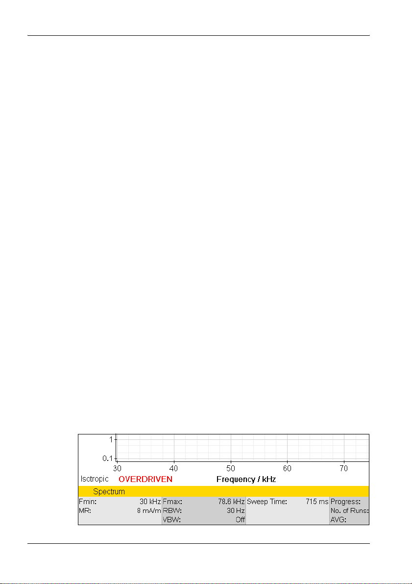
6 Functions Common to More Than One Operating Mode
6.3.2 Automatic measurement range search (MR Search)
Safety Evaluation • Meas. Range • MR Search
This softkey initiates a search for a suitable measurement range. This is
recommended if the field situation is unknown.
⇒ Press the MR Search softkey.
ª The message: Searching for best measurement range. Please
wait. is displayed. A measurement over the entire frequency range
covered by the antenna you are using is made in the background.
This takes several seconds. When it is completed, the device sets the
measurement range to the optimum value automatically and reverts
to normal measurement mode.
Note: Press the ESC key if you want to cancel the process.
MR Search Type
The SRM-3006 provides two types of measurement range search which can
be selected using the MR Search Type softkey (toggle function):
• Normal: This type is suitable for all largely static signals.
• Conserv.: This type allows for a higher overload reserve. It is better to set
the measurement range manually if pulsed signals are being measured.
To select the search type:
⇒ Press the MR Search Type softkey.
ª The switch toggles between the two types each time the softkey is
pressed.
6.3.3 Measurement input overload
If the signal level is higher than the range that can be measured, the warning
message OVERDRIVEN is shown in the display (in the part above the lower
status line, next to the axis setting).
74 SRM-3006 Narda
Page 87

6 Functions Common to More Than One Operating Mode
6.4 Selecting the result type (Result Type)
Safety Evaluation • Result Type
Spectrum Analysis • Result Type
UMTS • Result Type
The result type defines how the measured values are evaluated. One value
for each type is shown for each service.
The following Result Types can be selected / deselected (more than one
can be selected at the same time):
Table 20: Result types listed in the Result Type box
Type Abbreviation Explanation
Actual Act Actual value measured at the moment.
Maximum Max Maximum value measured.
Maximum Average MxA Maximum value of all averaged values.
Average Avg Average value over a specified number of
Minimum Average MnA Minimum value of all averaged values.
Minimum Min Minimum value measured.
Standard Std Shows the permitted limit value as an
measurements or over a specified time
(RMS).
unweighted limit curve.
To select or deselect a result type:
1. Press the Result Type softkey.
2. Use the rotary control and the softkeys to make the desired selection.
For information on how to do this, see Selecting entries from a list
on page 47.
3. When you have made your selection, press the OK key.
ª The selected result types will be used.
Information about the Standard (Std) result type:
• The Standard (Std) result type is only displayed when an antenna has
been selected or a Narda antenna is used.
• If you set the units to “%”, Standard (Std) will be set to 100%.
• Std corresponds to the unweighted limit value curve when field strength
units are used. If this value is way above the measured values, it is
possible that the limit value curve may no longer be displayed.
Narda SRM-3006 75
Page 88

6 Functions Common to More Than One Operating Mode
6.4.1 Average formation (Result type: Average)
An average can be formed over a specific number of measurements or over
a period of time.
Taking the average of a number of measurements:
✓ Result type Average is selected (the actions described below can
nevertheless be carried out even if this result type is not selected).
1. Press the Result Type softkey.
2. Press the Average Type softkey until Average Time is shown (toggle
function).
Note: If you operate the rotary control after opening the selection window,
the softkeys for selecting the average type and the parameters for
forming the average will be blanked out. If this happens, close the
selection window (press ESC) and then open it again.
3. Press the No. of Avg softkey, then use the rotary control to select the
desired number of measurements, and then press the OK key.
ª The measurements start. The AVG line shows the selected number
of measurement values and a bar graph next to this shows the
progress towards the formation of the first average value.
Taking the average over a period of time:
✓ Result type Average is selected (the actions described below can
nevertheless be carried out even if this result type is not selected).
1. Press the Result Type softkey.
2. Press the Average Type softkey until No. of Avg is shown.
Note: If you operate the rotary control after opening the selection window,
the softkeys for selecting the average type and the parameters for
forming the average will be blanked out. If this happens, close the
selection window (press ESC) and then open it again.
3. Press the Average Time softkey, then use the rotary control to select the
desired time period, and then press the OK key.
ª The measurements start. The AVG line shows the selected time
period numerically and a bar graph next to this shows the progress
towards the formation of the first average value.
76 SRM-3006 Narda
Page 89

6 Functions Common to More Than One Operating Mode
6.4.2 Reset measurement values
You can reset the values for Max, MxA, Avg, MnA, and Min:
• Reset All: Resets all the above-mentioned measurement
values.
• Reset Min & Max: Resets the Minimum (Min) and Maximum (Max)
measurement values only.
6.5 The Marker function
Spectrum • Marker
The Marker function is very useful for marking and comparing specific
individual frequencies in the display. The following types of marker function
can be selected:
• Two independent markers.
• Individual display of each marker or display of the difference between the
markers.
• Automatic location of the highest peak value.
• Automatic location of the next peak values.
Note: The markers allow access to all measured values, e.g. to every
spectral line measured. The spacing between two measured values
(two spectral lines) is approximately half the currently selected
resolution bandwidth.
Tip: Turning the rotary control slowly causes the marker to jump in small
frequency steps. Turning the control faster causes larger frequency
jumps. Briefly turning the control in the opposite direction stops the
marker movement.
Narda SRM-3006 77
Page 90
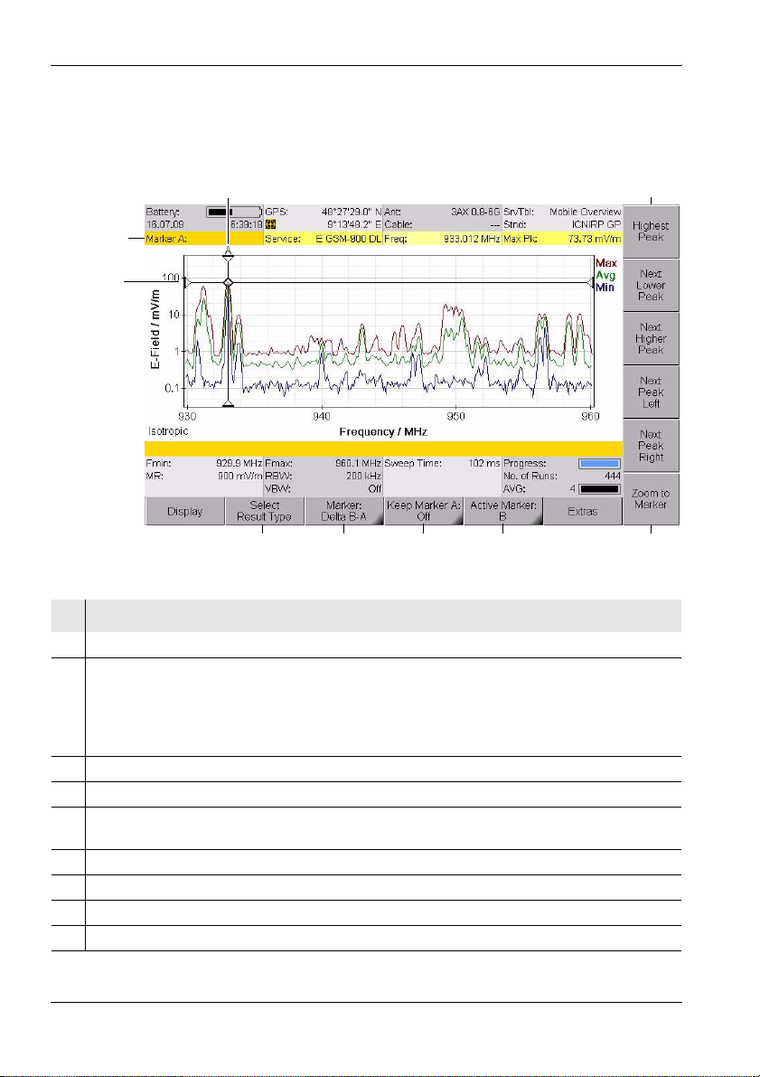
6 Functions Common to More Than One Operating Mode
6.5.1 Using the markers separately
The two markers A and B can be displayed separately and set
independently of each other by using the Single marker function.
3
2
1
4
9
Figure 17: Single marker display
No. Function / Description
1 Graphical display of the measurement value at the marker position.
2 Marker information:
• Marker A: Marker A is active.
• Service: Selected service.
• Freq: Frequency at the marker position.
• Max. Pk: Selected result type and measured value.
3 Graphical display of the marker position (for result type Max in the example).
4 Marker functions for peak value selection (see Table 21 on page 79).
5 Zoom function: Sets the marker to the center frequency and enlarges the display around the
marker (reduces the span).
6 Active marker (Marker A is active in the example).
7 Marker display on the measurement screen (Marker A is shown in the example).
8 Display type (Single is selected in the example).
9 Result type selection for the active marker.
7
6
58
78 SRM-3006 Narda
Page 91

6 Functions Common to More Than One Operating Mode
To use the markers separately:
Note: Remember that the softkeys always show the function that can be
selected, not the function that is currently active.
Example: if Delta B-A is shown, this means that the Single marker
function is active.
1. Press the Marker softkey until Delta B-A is shown (toggle function).
2. Press the Active Marker softkey until Marker A (if you want to use
Marker B) or B (if you want to use Marker A) is shown (toggle function).
3. Select a result type by pressing the Select Result Type softkey,
selecting a result type with the rotary control and then pressing the OK
key.
You can now use the available functions separately for markers A and B:
Table 21: Marker functions for selecting peak values
Selection Function
Rotary control Moves the marker to the desired position manually.
Highest Peak softkey Places the marker on the highest peak value.
Next Lower Peak softkey Places the marker on the next lower peak value.
Next Higher Peak softkey Places the marker on the next higher peak value.
Next Peak Left softkey Places the marker on the next peak value to the left of
Next Peak Right softkey Places the marker on the next peak value to the right
the previous position.
of the previous position.
Note: An algorithm that covers all the measurement values contained in
the spectrum is used for the Peak markers.
Narda SRM-3006 79
Page 92

6 Functions Common to More Than One Operating Mode
6.5.2 Using both markers to determine a difference
The difference between the two marker positions can be determined using
the Delta B-A marker function.
3
2
1
4
68
Figure 18: Display with both markers
No. Function / Description
1 Graphical display of the measurement values at the marker positions.
2 Marker information:
• Marker...: Marker A is active (black lettering), Display of difference B-A.
• Service: Selected services.
• Freq: Frequencies at the marker positions, frequency difference f
• Max. Pk: Selected result types and measured values, ratio of measured values B/A.
3 Graphical display of the marker positions (for result types Act and Max in the example).
4 Marker functions for peak value selection (see Table 21 on page 79).
5 Zoom function: Sets the marker to the center frequency and enlarges the display around the
marker (reduces the span). See also The Zoom function (Zoom) on page 114.
6 Active marker (Marker B is active in the example)
7 Marker display on the measurement screen (Marker B is not shown on the measurement
screen in the example).
8 Display type (the difference (Delta B-A) is selected in the example.
9 Result type selection for the active marker.
B
- fA.
579
80 SRM-3006 Narda
Page 93

6 Functions Common to More Than One Operating Mode
To use the Delta function:
Note: Remember that the softkeys always show the function that can be
selected, not the function that is currently active.
Example: if Single is shown, this means that the difference function
Delta B-A is active.
1. Press the Marker softkey until Single is shown (toggle function).
2. Press the Active Marker softkey until Marker B is shown: this means
that Marker A is selected (toggle function).
3. Select a result type for Marker A using the Select Result Marker softkey.
4. Move Marker A to the desired position (either manually or using the Peak
functions).
5. Press the Active Marker softkey until Marker A is shown: this means
that Marker B is selected (toggle function).
6. Select a result type for Marker B.
The difference determined depends on the result types selected for
Marker A and Marker B:
• Same result type for Marker A and Marker B:
The difference between the measured values of one result type at two
different frequencies is determined.
• Different result types for Marker A and Marker B:
The difference in the measured values between the two result types at
one frequency is determined.
7. Move Marker B to the desired position (either manually or using the Peak
functions).
ª The selected frequencies and the corresponding measured values
along with the difference are displayed in the upper status bar.
Narda SRM-3006 81
Page 94
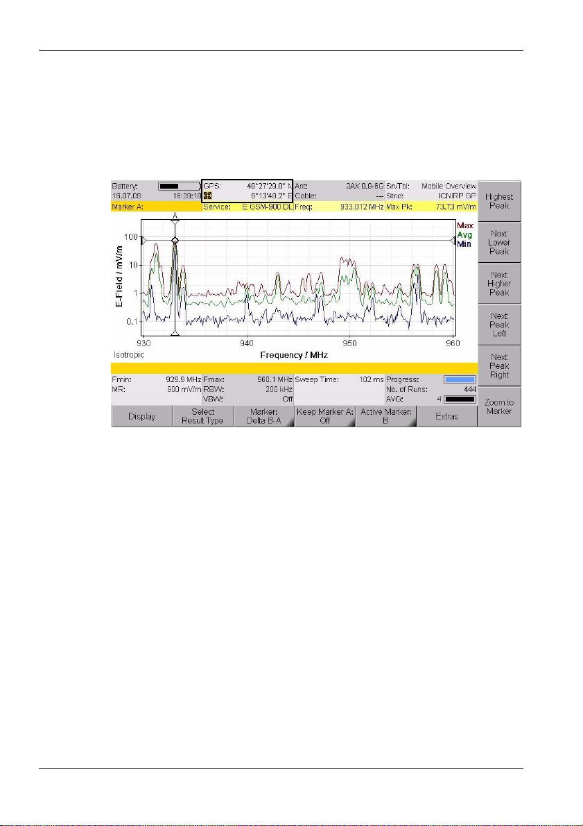
6 Functions Common to More Than One Operating Mode
6.5.3 Displaying the marker data on the measurement screen
If you activate the Marker function (Keep Marker = On), the frequency and
measured value corresponding to the active marker are displayed in the
upper status bar instead of the GPS data.
Figure 19: Display of marker data in the upper status bar.
To activate the display function:
✓ The Marker menu is active.
1. Press the Keep Marker A or Keep Marker B softkey until On is shown.
(If you select the other marker, the Keep Marker softkey changes to
reflect the choice of the new marker.)
2. Press the ESC key to return to the measurement screen.
82 SRM-3006 Narda
Page 95

6 Functions Common to More Than One Operating Mode
6.5.4 Zooming to marker
The Zoom to Marker function allows you to display an enlargement of a
section around the current marker position. The marker position is used
here as the center frequency of the zoomed display, and the frequency limits
are adjusted to suit.
To zoom to the marker:
1. Set the marker to the desired position.
2. Press the Zoom to Marker softkey.
ª The display is adjusted accordingly.
3. Press Zoom to Marker again to further enlarge the display.
To reset the display to the full frequency range:
1. Exit from the Marker menu.
2. Press the Set Freq softkey until Fmin & Fmax is displayed.
3. Press the Fspan softkey and then select Full Span.
ª The full frequency range is displayed once more.
Narda SRM-3006 83
Page 96

6 Functions Common to More Than One Operating Mode
6.6 Selecting an axis mode
Safety Evaluation • Axis
Spectrum • Axis
Level Recorder • Axis
UMTS • Axis
Scope • Axis
Depending on the antenna type being used (single axis or isotropic) you can
use the Axis softkey to select the axis to be measured or the axis mode in
the case of isotropic antennas.
To select the axis or the axis mode:
1. Press the Axis softkey.
ª The selection window opens.
– X-Axis, Y-Axis, Z-Axis: Axes for a single axis antenna
– Automatic Isotropic: Automatic isotropic measurement (default for
isotropic antennas)
– Manual Isotropic: Measurement of each axis separately with an
isotropic antenna
2. Select the item you require (see descriptions below) and confirm by
pressing OK.
The following constellations are possible with the selections listed above:
Single axis antenna
1. Align the antenna on one axis (e.g. X axis).
2. Select X-Axis in the Axis menu and measure the X axis.
3. Repeat the above for the Y and Z axes.
84 SRM-3006 Narda
Page 97

6 Functions Common to More Than One Operating Mode
6.6.1 Measurement using a three axis antenna
Three axis (isotropic) antennas allow you to make simple and quick isotropic
measurements by automatically detecting the three spatial components of
the field to be measured. Narda Safety Test Solutions offers three antennas
for measuring electric or magnetic field strength:
Table 22: Three axis antenna types
Type Frequency range Preferred application
E-field antenna
(isotropic), dipole
array, passive
E-field antenna
(isotropic), dipole
array, passive
H-field antenna
(isotropic), coil
array, active
It is of course possible to also measure each axis separately using a three
axis antenna.
Isotropic measurement
Isotropic measurement mode is selected automatically by default. All three
axes are measured one after the other and the isotropic result calculated
and displayed by the SRM-3006. The display shows the label Isotropic at
lower left.
420 MHz – 6 GHz Fast, non-directional measurements
e.g. at mobile communications and
WiMAX frequencies.
27 MHz – 3 GHz Fast, non-directional measurements
e.g. at mobile communications
frequencies.
9 kHz – 250 MHz Fast, non-directional near-field
magnetic field measurements on
radio/TV transmitters and industrial
equipment.
Measuring a single axis
Isotropic measurement mode is selected automatically when a three axis
antenna is used.
You can measure each axis separately from the Axis menu for those
applications where additional information about the spatial components of
the field is required.
The measurement is only useful if the orientation of the sensors relative to
the field is known. A tripod with a special antenna holder can be used for
Narda antennas (see Fitting a Narda antenna on a tripod on page 33). The
positions of the three measurement axes are marked on this special holder.
Narda SRM-3006 85
Page 98

6 Functions Common to More Than One Operating Mode
Two methods can be selected:
Automatic isotropic
This is the usual setting for isotropic antennas. All three axes are measured
automatically and the overall result is calculated.
Manual isotropic
As with a single axis antenna, each of the three axes can be measured
separately with this setting. However, it is not necessary to turn the antenna
in the direction of each axis. The procedure is as follows:
✓ A three axis antenna is connected directly or via a cable to the
SRM-3006.
1. Select the Manual Isotropic function from the Axis menu.
2. Press the Start X-Axis softkey. When the measurement finishes, press
the Stop X-Axis softkey.
3. Do the same for the Y axis and Z axis.
4. Press the Show Isotropic softkey to display the measurement result.
To make another measurement:
Press the Start X-Axis softkey and proceed as described above.
To change the settings:
1. Press the Change Settings softkey and then change the settings.
2. Press the Back to Axis softkey (highlighted in yellow) to return to
measurement mode.
To finish manual isotropic measurement:
⇒ Press the Axis softkey and select Automatic Isotropic.
6.6.2 Measurement using a single axis antenna
Isotropic measurement using a single axis antenna is much more timeconsuming than using a three axis antenna because each of the three axes
has to be measured separately, one after the other.
The SRM-3006 provides support for sequential measurements using single
axis antennas and for calculating the isotropic result.
The sections below explain how such measurements can be made.
You can of course use any suitable standard antenna and corresponding
cable as well as the items supplied with the instrument.
86 SRM-3006 Narda
Page 99

6 Functions Common to More Than One Operating Mode
Information about how to fit the antenna to a tripod is found in section 3.4.4
from page 33 onwards.
Table 23: Single axis antenna types
Type Frequency range Preferred application
E-field antenna,
dipole, passive
E-field antenna,
dipole, passive
H-field antenna,
coil, active
27 MHz – 3 GHz Precision measurements at UHF and
TV frequencies.
9 kHz – 300 MHz Precision electric field measurements
on radio/TV transmitters and industrial
equipment.
9 kHz – 300 MHz Precise near-field magnetic field
measurements on radio/TV transmitters
and industrial equipment.
Single axis measurement
This is the default measurement for single axis antennas.
✓ A single axis or standard antenna is connected directly or by a cable to
the SRM-3006.
⇒ Select the Single Axis function from the Axis menu (default).
Isotropic measurement
The SRM-3006 provides a sequential measurement for making an isotropic
measurement using a single axis antenna. The three separate
measurements are made one after the other and the overall result is
calculated and displayed.
Note: Directional antennas such as log-periodic antennas are basically
unsuitable for such sequential measurements.
To make an isotropic measurement with a single axis antenna:
✓ A single axis or standard antenna is connected directly or by a cable to
the SRM-3006.
1. Select the Manual Isotropic function from the Axis menu.
2. Position the antenna in the direction of the X axis, and press the
Start X-Axis softkey. When the measurement has finished, press the
Stop X-Axis softkey.
3. Follow the same procedure for the Y axis and the Z axis.
4. Press the Show Isotropic softkey to display the measurement result.
To make another measurement:
Press the Start X-Axis softkey and proceed as described above.
Narda SRM-3006 87
Page 100

6 Functions Common to More Than One Operating Mode
To change the settings:
1. Press the Change Settings softkey and then change the settings.
2. Press the Back to Axis softkey (highlighted in yellow) to return to
measurement mode.
To finish isotropic measurement:
⇒ Press the Axis softkey and select Single Axis.
6.7 Adjusting the Y axis
Spectrum • Display • Y-Scale...
Level Recorder • Display • Y-Scale...
Scope • Display • Y-Scale...
There are two ways of adjusting the Y axis:
• Manual adjustment of Y axis scaling and reference point
• Automatic adjustment of Y axis
Adjusting the Y axis manually
You can change the scaling as well as the reference point of the Y axis.
Changes you make are applied immediately.
To change the Y axis scaling:
1. Press the Y-Scale Range softkey.
2. Use the rotary control to highlight the desired value.
ª The change is applied to the display immediately.
3. Press the OK key or the ESC key.
To change the Y axis reference point:
1. Press the Y-Scale Ref softkey.
2. Use the rotary control to highlight the desired value.
ª The change is applied to the display immediately.
3. Press the OK key or the ESC key.
Adjusting the Y axis automatically
⇒ Press the Y-Scale Auto softkey.
ª The Y axis is adjusted automatically.
In this case, the scaling (Y-Scale Range) is set to 100 dB and the reference
point (Y-Scale Ref) is the same as the measurement range (MR+0 dB).
88 SRM-3006 Narda
 Loading...