


NARDA
Safety
Test
Solutions
S.r.l. Socio Unico
Sales & Support:
Via Leonardo da Vinci, 21/23
20090 Segrate (MI) -
ITALY
Tel.: +39 02 2699871
Fax: +39 02 26998700
Manufacturing Plant:
Via Benessea, 29/B
17035 Cisano sul Neva (SV)
Tel.: +39 0182 58641
Fax: +39 0182 586400
http://www.narda-sts.it
SERIAL NUMBER OF THE INSTRUMENT
You can find the Serial Number on the rear panel of the instrument.
Serial Number is in the form: 0000X00000.
The first four digits and the letter are the Serial Number prefix, the last five digits are the
Serial Number suffix. The prefix is the same for identical instruments, it changes only
when a configuration change is made to the instrument.
The suffix is different for each instrument.
Document 9010EN-81037-2.57 - Copyright © NARDA 2018
User’s Manual
PMM 9010
EMI CISPR RECEIVER
10 Hz ÷ 30 MHz
Including description of:
- PMM 9010F Fast EMI CISPR Receiver
10 Hz ÷ 30 MHz Full compliance
- PMM 9010/03P EMI CISPR Receiver
10 Hz ÷ 30 MHz Full compliance
30 MHz ÷ 300 MHz Compliance (PRF ≥ 10Hz)
- PMM 9010/30P EMI CISPR Receiver
10 Hz ÷ 30 MHz Full compliance
30 MHz ÷ 3 GHz Pre compliance
- PMM 9010/60P EMI CISPR Receiver
10 Hz ÷ 30 MHz Full compliance
30 MHz ÷ 6 GHz Pre compliance
- PMM 9030 EMI CISPR Receiver
Full compliance extension (up to 3 GHz)
- PMM 9060 EMI CISPR Receiver
Full compliance extension (up to 6 GHz)
- PMM 9180 EMI CISPR Receiver
Full compliance extension (up to 18 GHz)
- PMM 9010/Click Analyzer option

II
Note and symbols
NOTE:
® Names and Logo are registered trademarks of Narda Safety Test Solutions GmbH and L3 Communications
Holdings, Inc. – Trade names are trademarks of the owners.
If the instrument is used in any other way than as described in this User’s Manual, it
may become unsafe.
Before using this product, the related documentation must be read with great care and fully understood to familiarize
with all the safety prescriptions.
To ensure the correct use and the maximum safety level, the User shall know all the instructions and
recommendations contained in this document.
This product is a Safety Class I instrument according to IEC classification and has
been designed to meet the requirements of EN61010-1 (Safety Requirements for
Electrical Equipment for Measurement, Control and Laboratory Use).
In accordance with the IEC classification, the power supply of this product meets requirements Safety Class II and
Installation Category II (having double insulation and able to carry out mono-phase power supply operations).
It complies with the requirements of Pollution Class II (usually only non-conductive pollution). However,
occasionally it may become temporarily conductive due to condense on it.
The information contained in this document is subject to change without notice.
EXPLANATION OF ELECTRICAL AND SAFETY SYMBOLS :
You now own a high-quality instrument that will give you many years of reliable service.
Nevertheless, even this product will eventually become obsolete. When that time comes, please
remember that electronic equipment must be disposed of in accordance with local regulations.
This product conforms to the WEEE Directive of the European Union (2002/96/EC) and belongs to
Category 9 (Monitoring and Control Instruments). You can return the instrument to us free of
charge for proper environment friendly disposal. You can obtain further information from your
local Narda Sales Partner or by visiting our website at www.narda-sts.it .
Warning, danger of electric shock
Earth
Read carefully the Operating Manual and its
instructions, pay attention to the safety
symbols.
Unit Earth Connection
Earth Protection
Equipotential
EXPLANATION OF SYMBOLS USED IN THIS DOCUMENT :
The DANGER sign draws attention to a serious risk to a person’s safety,
which, if not avoided, will result in death or serious injury. All the
precautions must be fully understood and applied before proceeding.
The WARNING sign indicates a hazardous situation, which, if not avoided,
could result in death or serious injury. All the precautions must be fully
understood and applied before proceeding.
The CAUTION sign indicates a hazardous situation, which, if not avoided,
could result in minor or moderate injury.
The NOTICE sign draws attention to a potential risk of damage to the
apparatus or loss of data.
The NOTE sign draws attention to important information.

EC Conformity III
Contents
Explanation of electrical and safety symbols……....…………………………
General safety considerations and instructions.………....………………….
PMM 9010 EC Declaration of Conformity ...................………………………...
PMM 9010F EC Declaration of Conformity ........................…………………...
PMM 9010/03P EC Declaration of Conformity .....................………………….
PMM 9010/30P EC Declaration of Conformity .....................………………….
PMM 9010/60P EC Declaration of Conformity .....................………………….
PMM 9030 EC Declaration of Conformity ............................………………….
PMM 9060 EC Declaration of Conformity ............................………………….
PMM 9180 EC Declaration of Conformity ............................………………….
PMM 9010/Click EC Declaration of Conformity ……………………………...
PMM 9010/Click4E EC Declaration of Conformity …………………………..
1. General Information
1.1 Documentation…………………………………………………………………..
1.2 Operating Manual changes…………………………………………………….
1.3 Introduction to PMM 9010………………………………………………………
1.4 Instrument Items………….……………………………………………………..
1.5 Optional accessories……………….…………………………………………...
1.6 Other accessories……………………………………………………………….
1.7 Main Specifications……………………………………………………………..
1.8 Front Panel………………………...…………………………………………….
1.9 Rear Panel……………………………………………………………………….
1.10 Functional Description………………………………………………………..
1.11 Ultra fast measurement: a unique feature of the PMM 9010……………..
1.12 Emission measurement……………..………………………………………..
Page
II
XIII
XIIII
XV
XVI
XVII
XVIII
XIX
XX
XXI
XXII
XXIII
Page
1-1
1-1
1-1
1-2
1-2
1-2
1-3
1-5
1-6
1-7
1-7
1-8
2 Installation
2.1 Introduction………………………………………………………………………
2.2 Initial Inspection……………………………….……………….………………..
2.3 Packing and Unpacking……………………………………….…………….….
2.4 Preparation for Use……………………………………………………………..
2.5 Battery Charger…………………………………………………….……………
2.5.1 To substitute the mains connector………………………………………….
2.5.2 To Check the internal batteries……………………………………………..
2.5.3 Indication of the battery on the screen and with PW led……..………….
2.6 Environment……………………………………………………………………..
2.7 Return for Service……………………………………………………………….
2.8 Equipment Cleaning…………………………………………………………….
2.9 Equipment ventilation…………………………………………………………...
2.10 Hardware Installation………………………………………………………….
2.11 Using an Artificial Mains Network (AMN or LISN)………………………….
2.12 Using Pulse Limiter……………………………………………………………
2.13 Using Current and Voltage Probes……………………………………….….
2.14 Using Antennas and other Transducers………………………………….…
2.15 The User Port…………………………………………………………………..
2.16 PMM L2-16A remote cable Configuration for PMM 9010………...............
2.17 PMM LISN three phase remote cable Configuration for 9010…………….
2.18 PMM L2-16 remote cable Configuration for PMM 9010…………………...
2.19 PMM L3-25 remote cable Configuration for PMM 9010…………………...
Page
2-1
2-1
2-1
2-1
2-1
2-1
2-1
2-2
2-2
2-3
2-3
2-3
2-3
2-4
2-4
2-5
2-5
2-5
2-6
2-7
2-8
2-9
3 Setup and Panel Instructions
3.1 Introduction………………………………………………………………………
3.2 Display……………………………………………………………………………
3.3 Autocal……………………………………………………………………………
3.4 Unit………………………………………………………………………………..
3.5 RF OUT…………………………………………………………………………..
3.6 Panel……………………………………………………………………………..
3.7 RS 232 (Speed)…………………………………………………………………
Page
3-1
3-1
3-2
3-3
3-3
3-3
3-4

IV Safety considerations
4 Sweep Mode operating instructions
4.1 Introduction………………………………………………………………………
4.2 Measure………………………………………………………………………….
4.2.1 Frequency……………………………………………………………………...
4.2.2 Level………………….………………………………………………………...
4.2.2.1 Input: Attenuator and Preamplifier….…………………………………….
4.2.2.2 Misc…………………………………………………………….…………….
4.2.2.2.1 Tracking generator……………………………………………………….
4.2.2.3 Detector……………………………………………………………………...
4.2.2.4 Smart detector…………………………………………………..................
4.2.3 Conversion factor……………………………………………………………..
4.3 Limit………………………………………………………………………………
4.4 Display……………………………………………………………………………
4.5 Marker…………………………………………………………………………….
4.6 Load & Store.…………………………………………………………………….
4.7 Ultra fast FFT scan……………………………………………………………...
Page
4-1
4-2
4-2
4-3
4-3
4-4
4-4
4-5
4-5
4-6
4-6
4-6
4-7
4-8
4-8
5 Analyzer Mode operating instructions
5.1 Introduction………………………………………………………………………
5.2 Frequency………………………………………………………………………..
5.3 RBW………………………………………………………………………………
5.4 Level………………………………………………………………………………
5.4.1 Input Attenuators and Preamplifier……..…………………………………..
5.4.2 OVER RANGE Message…………………………………………………….
5.4.3 Misc…………………..…………………………………………………………
5.4.3.1 Tracking generator…………………………………………………………
5.4.4 Detector………..……………………………………………………………….
5.4.5 Conversion factor……………………………………………………………..
5.5 Marker……..….………………………………………………………………….
5.6 Esc………………………………………………………………………………..
Page
5-1
5-2
5-3
5-3
5-3
5-4
5-4
5-5
5-5
5-6
5-6
5-6
6 Manual Mode operating instructions
6.1 Introduction………………………………………………………………………
6.2 Frequency………………………………………………………………………..
6.3 Level………………………………………………………………………………
6.3.1 Input: Attenuator and preamplifier………………………………………….
6.3.2 Misc…………………………………………………………………………….
6.4 RBW………………………………………………………………………………
6.5 Hold Time………………………………………………………………………...
6.6 Demodulator……………………………………………………………………..
Page
6-1
6-2
6-2
6-3
6-3
6-5
6-5
6-5
7. Applications
7.1 Measuring the EMI Voltage……………………………………………………...
7.1.1 Measuring Principle with a LISN………………………………………….....
7.1.2 Coupling Networks……………………………………………………………
7.1.2.1 AMN…………………………………………………………………………..
7.1.2.2 Current probe……………………………………………………………….
7.1.2.3 Voltage probe……………………………………………………………….
7.1.3 Test setup……………………………………………………………………..
7.1.4 Guidance on a preliminary Measuring Procedure………………………..
7.1.5 Remarks and hints for Measuring…………………………………………..
Page
7-1
7-1
7-1
7-2
7-3
7-3
7-4
7-4
7-5
8. Updating firmware and Activation code Utility
8.1 Introduction………………………………………………………………………
8.2 System requirements ……………………………….………………………….
8.3 Preparing the Hardware…………………………….………………………….
8.4 Software installation…………………………………………………................
8.5 To transfer data……………….……………………………………..………….
8.6 9010 Set code utility ...……….……………………………………..………….
Page
8-1
8-1
8-1
8-1
8-3
8-5

EC Conformity V
9. PMM 9010/03P EMI CISPR Receiver
10 Hz ÷ 30 MHz Full compliance
> 30 MHz Compliance (PRF ≥ 10Hz)
PMM 9010/30P EMI CISPR Receiver
10 Hz ÷ 30 MHz Full compliance
30 MHz ÷ 3 GHz Pre compliance
PMM 9010/60P EMI CISPR Receiver
10 Hz ÷ 30 MHz Full compliance
30 MHz ÷ 6 GHz Pre compliance
General Information
9.1 Documentation…………………………………………………………………..
9.2 Operating Manual changes……………………………………………………
9.3 Introduction to PMM 9010/03P/30P/60P…...………………………………..
9.4 Instrument Items………….………………………………………………….....
9.5 Optional accessories……………….…………………………………………..
9.6 Other accessories………………………………………………………………
9.7 PMM 9010/03P Main Specifications…………………………………………..
9.8 PMM 9010/03P Front Panel……………..…………………………………….
9.9 PMM 9010/03P Rear Panel……………………………………………………
9.10 PMM 9010/30P Main Specifications…………..…………………………….
9.11 PMM 9010/30P Front Panel…………………….....………………...……….
9.12 PMM 9010/30P Rear Panel………………………..…………………………
9.13 PMM 9010/60P Main Specifications…………..…………………………….
9.14 PMM 9010/60P Front Panel…………………….....………………...……….
9.15 PMM 9010/60P Rear Panel………………………..…………………………
9-2
9-2
9-3
9-4
9-4
9-4
9-5
9-6
9-7
9-8
9-9
9-10
9-11
9-12
9-13
10 Click Mode Operating Instructions (Option)
10.1 Introduction……………………………………………………………………..
10.2 Click Mode Activation procedure…………………………………………….
10.3 Enter the Click Mode…………………………………………………….……
10.4 Introduction to the discontinuous disturbance (click) measurement….....
10.4.1 Determination of click rate………………………………………………….
10.4.2 Preliminary Conformity and Exceptions…………………………………..
10.4.2.1 Old and New exceptions…………………………………………………
10.4.3 Calculate Limit Quartile…………………………………………………….
10.4.4 Measurements vs Lq limit…………………………………………………..
10.5 Start………………………………………………………………………..……
10.5.1 Stop and pause…………………………………………………………..…
10.6 Report…………………………………………………………………………..
10.6.1 Fail during determination of the click rate N……………………………...
10.6.2 Report after a successful test with less than 5 instantaneous ………...
switching at one frequency…………………………………………..……..
10.6.3 Report after a successful test at 4 frequencies………………………….
10.6.4 Report after a line search…………………………………………………..
10.7 Setup…………………………………………………………….………………
10.7.1 External attenuator………………………………………………................
10.7.2 Limit…………………………………………………………………………...
10.7.3 Determination of N…………………………………………………………..
10.7.4 Factor f………………………………………………………………………..
10.7.5 Stop on Fail………………………………………………………................
10.7.6 Terminate on…………………………………………………………………
10.7.7 Line……………………………………………………………………………
10.7.8 Max time………………………………………………………………………
10.7.9 Idle Frequency.………………………………………………………………
10.7.10 Idle Level……………………………………………………………………
10.7.11 Smart Measure…………………………………………………………….
10.8 Click option…………………………………………………………………….
10.8.1 Optional PMM 9010 Click4E Four Channels Click meter ………………
10.9 Test setup………………………………………………………………………
10.10 Diagnostic…………………………………………………………………..…
10.11 Click reports with PMM Emission Suite ……………………………………
Page
10-1
10-1
10-4
10-5
10-6
10-6
10-6
10-7
10-7
10-7
10-9
10-9
10-9
10-9
10-10
10-10
10-11
10-11
10-12
10-13
10-13
10-13
10-14
10-14
10-16
10-16
10-16
10-16
10-17
10-17
10-18
10-18
10-19

VI Safety considerations
11 PMM 9030/9060/9180 EMI CISPR Receiver extension
30 MHz – 3GHz / 6GHz / 18GHz (Option)
11.1 Introduction to PMM 9030/9060/9180……………………………………
11.2 Instruments items………..…………………………………………………
11.3 Optional PMM accessories………..………………………………………
11.4 Other accessories…………………..………………………………………
11.5 PMM 9030 Main specifications.…………………………………………..
11.6 PMM 9030 Front and rear panel…………………………………………
11.7 PMM 9060 Main specifications.…………………………………………..
11.8 PMM 9060 Front and rear panel…………………………………………
11.9 PMM 9180 Main specifications.…………………………………………..
11.10 PMM 9180 Front and rear panel………………………………………..
11.11 Functional description……………………………………………………
11.12 No coaxial cable between the antenna and the receiver…………….
11.13 Emission measurements………………………………………………..
11.14 Installation…………………………………………………………………
11.14.1 Introduction……………………………………………………………..
11.14.2 Initial inspection………………………………………………………..
11.14.2.1 Packing and Unpacking…………………………………………….
11.14.3 Preparation for use…………………………………………………….
11.14.4 Battery charger…………………………………………….…………..
11.14.4.1 To replace the mains connector of the battery charger…………
11.14.4.2 To charge the internal battery…….………………………………..
11.14.4.3 To Supply 9030/9060/9180 through the mains power socket by
SPA-01........................................................................................................
11.14.4.4 Indication of the battery status on the screen and with PW led…
11.14.5 Environment……………………………………………………………..
11.14.6 Return for Service…………………………………………….…………
11.14.7 Equipment cleaning……………………………………….……………
11.14.8 Equipment ventilation……………………………………..……………
11.14.9 Hardware installation…………………………………………………...
11.14.10 PMM 9010+ PMM 9030/9060/9180 initial screen…………………
11.14.11 Led on the PMM 9010 and on the PMM 9030/9060/9180..………
11.14.12 PMM 9010 + PMM 9030/9060/9180 main screen…………………
11.14.13 PMM 9010 + PMM 9030/9060/9180 Setup panel………………….
11.14.14 PMM 9010 + PMM 9030/9060/9180 Link failure…………………..
11.14.15 Antenna Mounting Kit AMK-01 and AMK-02………..…………......
Antenna Mounting Kit AMK-01 with BL-01, LP-02, LP-04, AS-02, AS-03, AS-
04, AS-05 and AS-06..................................................................……….
Antenna Mounting Kit AMK-01 with LP-03……………………………………..
Antenna Mounting Kit AMK-02 with BL-01, AS-07 and AS-08,,,…………….
11.15 Analyzer Mode operating instructions……………………………….....
11.15.1 Introduction………………………………………………………………
11.15.2 Frequency…………………………………………………..……………
11.15.3 RBW……………………………………………………………………...
11.15.4 Level……………………………………………………………………...
11.15.4.1 Input: Attenuators and preamplifier…………………………………
11.15.4.2 Misc……………………………………………………….……………
11.15.4.3 Detector…………………………………………………...…………..
11.15.4.4 Conversion factor………………………………………..…………...
11.15.5 Marker……………………………………………………….……………
11.15.6 ESC…………………………………………………………….…………
Page
11-1
11-2
11-2
11-2
11-3
11-5
11-6
11-8
11-9
11-11
11-12
11-12
11-13
11-14
11-14
11-14
11-14
11-14
11-14
11-14
11-14
11-14
11-15
11-16
11-16
11-16
11-16
11-17
11-18
11-18
11-18
11-19
11-20
11-21
11-21
11-25
11-27
11-37
11-37
11-38
11-38
11-39
11-39
11-40
11-40
11-41
11-41
11-41

EC Conformity VII
11.16 Sweep Mode operating instructions…………………………………….
11.16.1 Introduction………………………………………………………………
11.16.2 Measure………………………………………………………..…………
11.16.2.1 Frequency………………………………………………………………
11.16.2.2 Advanced…………………………………………………….…………
11.16.2.3 Level…………………………………………………………………….
11.16.2.3.1 Input: Attenuators and preamplifier…………………………………
11.16.2.3.2 Misc……………………………………………………..………….
11.16.2.3.3 Tracking generator……………………………………………….
11.16.2.3.4 Detector……………………………………………………………
11.16.2.4 Conversion factor…………………………………………...…………
11.16.3 Limit………………………………………………………….…………
11.16.4 Display……………………………………………………….………..…
11.16.5 Marker………………………………………………………….…………
11.16.6 Load store………………………………………………..……………...
11.17 Manual Mode operating instructions…………………………………….
11.17.1 Introduction………………………………………………………………
11.17.2 Frequency……………………………………………………...………..
11.17.3 Level………………………………………………………………………
11.17.3.1 Input: Attenuator and preamplifier………………………….……....
11.17.3.2 Misc…………………………………………………………..………..
11.17.4 RBW……………………………………………………………………...
11.17.5 Hold me……………………………………………………...…………...
11.17.6 Demodulator…………………………………………………...…………
11.18 Updating firmware…………………………………………………………
11.18.1 Introduction………………………………………………………………
11.18.2 System requirements ……………………………….…………………
11.18.3 Preparing the Hardware…………………………….………………….
11.18.4 Software installation………………………………………………….....
11.18.5 To transfer data……………….……………………………………..….
11-42
11-42
11-43
11-43
11-44
11-44
11-45
11-45
11-45
11-46
11-46
11-46
11-47
11-47
11-48
11-49
11-49
11-50
11-50
11-51
11-52
11-52
11-53
11-53
11-54
11-54
11-54
11-54
11-54
11-56
12 PMM 9010-RMA Rack Mount Adapter for Rack 19”
12.1 Introduction……….………………………………………………………..
12.2 Instruments Items…………………………...…………………………….
12.3 Optional accessories………………………………………………………
12.4 PMM 9010-RMA Main Specifications……………………………………
12.5 PMM 9010-RMA Front view………………………………...…………….
12.6 PMM 9010-RMA Inside view…………………………..…...……………..
12.7 Rack requirements……………..……….…………………...……………..
12.8 Required equipment…………………..………………..…...……………..
12.9 Moving chassis……………….……………..……………………………...
12.10 Installation guidelines ……………………………………………………
12.11 Installing the PMM 9010-RMA……………………………………..……
12.12 Use of the PMM 9010-RMA with PMM 9010……………………….….
12-1
12-1
12-1
12-2
12-2
12-3
12-4
12-4
12-4
12-5
12-6
12-7

VIII Safety considerations
13 APD Mode Operating Instructions (Amplitude Probability Distribution)
13.1 Introduction……….……………………………………………………………………
13.2 Pre-conditions and Settings………………..………………………………………..
13.2.1 Entering the function …………..…………………………………………………..
13.2.2 Methods ………………………………………..…………………………………...
13.3 Setup……………………………… …………………………………………………..
13.3.1 Limit 1 E …………………….………………………………………………………
13.3.2 Limit 1 P ……………………….…………………………………………………….
13.3.3 Limit 2 E .……………………………………………………………………………
13.3.4 Limit 2 P …………….……………………………………………………………….
13.3.5 YY Offset …………………………………………………………………………….
13.3.6 Start Frequency …………………………………………………………………….
13.3.7 Stop Frequency……………………………………………………………………..
13.3.8 Num. of freqs ……………………………………………………………................
13.3.9 Time ……………………………..……………………………………………………
13.3.10 Method .…………………………………………………………………................
13.3.11 Search Hold Time ……………………………………………………..................
13.3.12 Conversion Factor …………………………………………………………………
13.3.13 Preselector …………………………………………………………………………
13.3.14 Min. Attenuation……………………………………………………………………
13.3.15 PreAmplifier ……………………………………………………………................
13.4 Operation ……………..……………………………………………………................
13.4.1 Manual (APD)………………………………………………………………………..
13.4.1.1 Frequency ..……………………………………………………………………….
13.4.1.2 Input ……………………………………………………………………………….
13.4.1.3 Clear ………..……………………………………………………………………..
13.4.1.4 Setup ………………………………………………………………………………
13.4.2 Report (APD) .……………………………………………………………………….
13.4.2.1 MHz ……….……………………………………………………………................
13.4.2.2 Pk dBµV ……………………………………………………………………………
13.4.2.3 ∆L Peak …………………………………………………………………………….
13.4.2.4 ∆L1 …………………………………………………………………………………
13.4.2.5 E …………………………………………………………………………………….
13.4.2.6 ∆L2 …………………………………………………………………………………
13.4.2.7 ………………………………………………………………………………………
13.4.2.8 Time ………………………………………………………………………………..
13.4.2.9 P/F …………………………………………………………………………………
13.4.3 Start (APD) ………………………………………………………………………….
13.4.3.1 Sweep running ……………………………………………………………………
13.4.3.2 Signal by signal measurements ………………………………………………..
13.4.3.3 Finish and Next Step …………………………………………………………….
13.4.3.4 Report ……………………………………………………………………………..
13.4.4 Default ……………………………………………………………………………….
13.5 Internal Generator ……………………………………………………………………
13.6 Panel Save and Recall ……………………………………………………................
13-1
13-2
13-3
13-3
13-4
13-4
13-4
13-4
13-5
13-5
13-5
13-5
13-5
13-6
13-6
13-6
13-6
13-6
13-7
13-7
13-8
13-8
13-9
13-10
13-11
13-11
13-12
13-12
13-12
13-12
13-12
13-12
13-12
13-12
13-12
13-12
13-13
13-13
13-13
13-14
13-14
13-14
13-15
13-15

EC Conformity IX
14 Remote control
14.1 Introduction ……….……………………………………………………………………
14.2 Communication …………….………………..………………………………………..
14.2.1 RS 232 (Speed) …….…………..………………………………………................
14.3 Protocol …………………………… ………………………………………................
14.4 Format ….……………..……………………………………………………................
14.5 PMM 9010 COMMANDs .…………………………………………………................
14.6 List of commands………………………………………………………………………
14.6.1 QUERY Commands .……………………………………………………................
14.6.2 SETTING Commands ..……………………………………………………………..
14.6.3 Analyzer Reply ………………………………………………………………………
14.6.3.1 Reply example …………………………………………………………………….
14.6.4 Sweep Structure …………………………………………………………………….
14.6.5 Procedure to read a measure stored by the PMM 9010 .……………………….
14.7 Special notes for 9010 Fast…………………………………………………………..
14.7.1 Analyzer Max-Hold function………………………………………………………..
14.7.1.1 Analyzer Max-Hold Activation……………………………………………………
14.7.1.2 Analyzer Max-Hold Reset………………………………………………………..
14.7.1.3 Analyzer Max-Hold Pause (suspend)…………………………………………..
14.7.1.4 Analyzer MAX-HOLD related COMMANDs…………………………………….
14.8 Sweep Mode commands sequence example………………………………………
Page
14-1
14-1
14-1
14-1
14-1
14-2
14-3
14-5
14-11
14-26
14-26
14-28
14-31
14-31
14-33
14-33
14-33
14-33
14-34
14-35
15 9010F Fast
15.1 Introduction to 9010F….……………………………………………………………….
15.1.1 Principle of operation.........………………..…………………………………………
15.1.2 Instrument Items…….…………..………………………………………...................
15.1.3 Optional accessories……..………….…………………………………...................
15.1.4 Other accessories………………….……………………………………..................
15.1.5 Main specification……………………………………………………………………
15.1.6 Functional description……………………………………………………………….
15.1.7 Ultra fast measurement: an unique feature of the PMM 9010F………………...
15.2 Sweep Mode……………………………………………………………………………
15.2.1 Ultra Fast FFT scan………………………………………………………………….
15.2.2 Measure……………………………………………………………………………….
15.2.2.1 Frequency…………………………………………………………………………..
15.2.2.2 Level…………………………………………………………………………………
15.2.2.3 Input: Attenuators and preamplifier……………………………………………...
15.2.2.4 Misc………………………………………………………………………………….
15.2.2.5 RF Output Generator………………………………………………………………
15.2.2.6 Detector……………………………………………………………………………..
15.2.2.7 Conversion factor………………………………………………………………….
15.2.3 Limit……………………………………………………………………………………
15.2.4 Display…………………………………………………………………………………
15.2.5 Market………………………………………………………………………………….
15.2.6 Load Store…………………………………………………………………………….
15.3 Analyzer Mode………………………………………………………………………….
15.3.1 Frequency……………………………………………………………………………..
15.3.2 RBW……………………………………………………………………………………
15.3.3 Level…………………………………………………………………………………...
15.3.3.1 Input: Attenuators and preamplifier……………………………………………...
15.3.3.2 OVER RANGE Message………………………………………………………….
15.3.3.3 MISC………………………………………………………………………………...
15.3.3.4 Tracking generator………………………………………………………………...
15.3.3.5 Detector……………………………………………………………………………..
15.3.3.6 Conversion factor………………………………………………………………….
15.3.4 Marker…………………………………………………………………………………
15-1
15-2
15-3
15-3
15-3
15-4
15-8
15-8
15-9
15-9
15-10
15-10
15-11
15-11
15-12
15-12
15-13
15-13
15-14
15-14
15-15
15-16
15-17
15-18
15-19
15-19
15-19
15-20
15-20
15-21
15-21
15-22
15-22
Annex - A RMS-AVG and C-AVG Detectors
A-A.1 Introduction……………………………………………………………………………
A-A.2 RMS-AVG Definition………………………………………………………………….
A.A.3 RMS-AVG Activation Procedure (option)…………………………………………..
A-A.4 C-AVG Definition……………………………………………………………………..
A-A.5 Sweep Mode…………………………………………………………………………..
A-A.5.1 Detector selection………………………………………………………………….
A-A.5.2 Smart Detector……………………………………………………………………..
A-A.6 Operating Manual Changes…………………………………………………………
A-A-1
A-A-1
A-A-1
A-A-3
A-A-4
A-A-4
A-A-5
A-A-6

X Safety considerations
Annex - B Additional RBW filters
A-B.1 Introduction……………………………………………………………………………
A-B.2 MIL-STD-461E Activation procedure (option)…..…………………………………
A-B.3 Analyzer Mode………………………………………………………………………...
A-B.3.1 RBW Selection……………………………………………………………………..
A-B.3.2 MIL Filters…………………………………………………………………………...
A-B.3.3 MIL Filters over 30MHz…………………………………………………………….
A-B.4 Manual Mode………………………………………………………………………….
A-B.4.1 RBW Selection…………………………………………………………..................
A-B.4.2 MIL Filters……………………………………………………………………………
A-B.4.3 Hold Time……………………………………………………………………………
A-B.5 Operating Manual Changes…………………………………………………………
Page
A-B-1
A-B-1
A-B-2
A-B-2
A-B-2
A-B-3
A-B-3
A-B-3
A-B-3
A-B-4
A-B-4
Annex - C Click4E Four Channels Click Meter Option
A-C.1 Introduction……………………………………………………………………………
A-C.2 Installation…………………………………………………………………………….
A-C.2.1 Initial Inspection……………………………………………………………………
A-C.2.2 Packing and Unpacking…………………………………………………………..
A-C.2.3 Preparation for Use………………………………………………………………..
A-C.2.4 Click4E Option mains supply……………………………………………………..
A-C.2.5 PMM 9010 Battery charging………………………………………………………
A-C.2.6 Indication of the battery status on the screen and with PW led………………
A-C.2.7 Environment………………………………………………………………………...
A-C.2.8 Return for Service………………………………………………………………….
A-C.2.9 Equipment Cleaning……………………………………………………………….
A-C.2.10 Equipment ventilation…………………………………………………………….
A-C.2.11 Hardware Installation…………………………………………………………….
A-C.3 Click Mode…………………………………………………………………………….
A-C.3.1 Using an Artificial Mains Network (AMN or LISN) ……………………………..
A-C.3.2 Using the Pulse Limiter……………………………………………………………
A-C.3.3 Click Mode menu………………………………………………………..................
A-C.4 Self Calibration……………………………………………………………………….
A-C.5 Operation………………………………………………………………………………
A-C.5.1 Smart Measure……………………………………………………………………..
A-C.6 Operating Manual Changes…………………………………………………………
A-C-1
A-C-2
A-C-2
A-C-2
A-C-2
A-C-2
A-C-3
A-C-4
A-C-4
A-C-5
A-C-5
A-C-5
A-C-5
A-C-6
A-C-6
A-C-6
A-C-7
A-C-7
A-C-8
A-C-8
A-C-8
Annex - D Measure the insertion loss of a Line Impedance Stabilization
Network (LISN) with a PMM 9010 Receiver
A-D.1 Introduction……………………………………………………………………………
A-D.2 Operation………………………………………………………………………………
A-D.3 Test setup……………………………………………………………………………..
A-D.4 Settings………………………………………………………………………………..
A-D.5 Measure the Insertion Loss (Voltage Division Factor)…………………………...
A-D.6 Connecting the LISN under test……………………………………………….........
A-D.7 Starting the Sweep…………………………………………………………………...
A-D.8 Marker………………………………………………………………………………….
A-D.9 LISNs with PMM Emission Suite…………………………………………...............
A-D-10 Note…………………………………………………………………………………..
A-D-11 PMM LISNs and Passive probes…...…………………………………………….
A-D.12 Conversion table dBμV <> μV <> dBm…………………………………………..
A-D-13 LISN Service kit.....................……………………………………………………..
A-D-1
A-D-1
A-D-1
A-D-1
A-D-2
A-D-2
A-D-3
A-D-4
A-D-4
A-D-5
A-D-6
A-D-7
A-D-8
Annex - E Procedure to connect to the PMM 9010 via a wireless Bluetooth
channel
A-E.1 Introduction……………………………………………………………………………
A-E.2 Wireless connection…………………………………………………………………
A-E.3 Test setup……………………………………………………………………………..
A-E.4 Installation……………………………………………………………………………..
A-E.5 PMM Emission Suite………………………………………….……………………...
A-E-1
A-E-1
A-E-2
A-E-2
A-E-4

EC Conformity XI
Figures
Figure
1-1
1-2
1-3
1-4
2-1
2-2
2-3
2-4
2-5
3-1
4-1
5-1
6-1
7-1
7-2
9-1
9-2
9-3
9-4
9-5
9-6
9-7
9-8
9-9
10-1
11-1
11-2
11-3
11-4
11-5
11-6
11-7
11-8
11-9
11-10
12-1
12-2
12-3
15-1
15-2
15-3
A-D-1
A-D-2
A-D-3
A-D-4
A-D-5
Front Panel 9010……………………………………………………….
Rear Panel 9010…………………………………………………….....
BP-02 Replaceable battery…………………………………………...
PMM 9010 Functional Diagram………………………………………
PMM 9010 initial screen showing the results of the initial self-test
and the five main function keys menu………………………………
PMM L2-16A remote cable configuration for 9010……………….
PMM LISN three phase remote cable configuration for 9010…..
PMM L2-16 remote cable configuration for PMM 9010…………..
PMM L3-25 remote cable configuration for PMM 9010…………..
Display setting..………………………………………………………..
Sweep…………………………………………………………………..
Spectrum…….…………………………………………………………
Manual…………………………………………………………………
AMN Principle: a) Δ-type or T-type LISN ; b) V-type LISN……….
Example of test Setup for RFI Voltage Measurements…………..
9010/03P Front Panel ………..……….……………………………..
9010/03P Rear Panel ………………………………………………..
BP-02 Replaceable battery for 9010/03P …………………………
9010/30P Front Panel ………..……….……………………………..
9010/30P Rear Panel ………………………………………………..
BP-02 Replaceable battery for 9010/30P …………………………
9010/60P Front Panel ………..……….……………………………..
9010/60P Rear Panel ………………………………………………..
BP-02 Replaceable battery for 9010/60P …………………………
Click……………………………………………………………………
PMM 9030 Front and rear panels…………………………………..
PMM 9060 Front and rear panels…………………………………..
PMM 9180 Front and rear panels…………………………………..
PMM 9030/9060/9180 Functional BLOCK Diagram……....……..
PMM 9030/9060/9180 Fiber Optic Link to PMM 9010……………
AMK-01 Antenna Mounting Kit …………………………..…………
AMK-02 Antenna Mounting Kit …………………………..…………
Spectrum…………………………………………………….…………
Sweep…………………………………………………………………..
Manual………………………………………………………………….
Front view 9010-RMA…………………………………………………
Inside view 9010-RMA………………………………………………..
PMM 9010-RMA with 9010 Instrument……………………………..
PMM 9010F Functional BLOCK Diagram………………………….
Sweep Model…………………………………………………………..
Spectrum……………………………………………………………….
Receiver verification………………………………………………….
Sweep………………………………………………………………….
Network analyzer calibration Setup (L1) …………………………..
Measurement Setup (L1) ……………………………………………
L1-150M: Single line LISN, 150A LISN….…………………………
Page
1-5
1-6
1-6
1-7
2-4
2-6
2-7
2-8
2-9
3-1
4-1
5-1
6-1
7-2
7-3
9-6
9-7
9-7
9-9
9-10
9-10
9-12
9-13
9-13
10-1
11-5
11-8
11-11
11-12
11-17
11-21
11-25
11-37
11-42
11-49
12-2
12-3
12-7
15-8
15-9
15-17
A-D-2
A-D-3
A-D-5
A-D-5
A-D-6

XII Safety considerations
Figure
Page
A-D-6
A-D-7
A-D-8
A-D-9
A-D-10
A-D-11
A-D-12
A-D-13
A-D-14
A-D-15
A-D-16
A-D-17
A-D-18
A-D-19
L2-16B: Two lines, Single phase, 16A LISN……………………………………………………….
L3-32: Four lines, 3-phase, 32A LISN……………………………....………………………..…….
L3-64: Four lines, 3-phase, 64A LISN…………………………………………………………..….
L3-64/690: Four lines, 3-phase, 64A – 690Vac LISN…..……………………………………..….
L3-100: Four lines, 3-phase, 100A LISN…………………………...…………………………..…..
L1-500: Single line LISN, 500A LISN………………………...…………………………..…………
L3-500: Four lines, 3-phase, 500A LISN………………………...…………………………..……..
Conversion table………………………………………………………………………………….….
PMM L2-16 model adapter…………………………………………..……………………………...
PMM L3-32 model adapter…………………………………..............……………………………...
PMM L3-64 model adapter…………………………………………...………………………….….
3-phase socket to BNC adapter……………………………………..………………………….…..
Rigid case………………………………………………………...........………………………….…..
Rigid case internal view…………………………………………………………………………..….
A-D-6
A-D-6
A-D-6
A-D-6
A-D-6
A-D-6
A-D-6
A-D-7
A-D-8
A-D-8
A-D-8
A-D-8
A-D-8
A-D-8
Tables
Table
1-1
9-1
9-2
9-3
10-1
11-1
11-2
11-3
12-1
15-1
Main Specifications 9010….………………………………………………………………………...
9010/03P Main Specifications for C bands……..…………………………………………………
9010/30P Main Specifications for CDE bands…………………………………...........................
9010/60P Main Specifications for CDE bands…………………………………...........................
Led status……………………...………………………………………............................................
Main Specifications 9030……………………………………………………………………………
Main Specifications 9060……………………………………………………………………………
Main Specifications 9180……………………………………………………………………………
Main Specifications 9010-RMA……………………………………………………………………..
Main Specifications 9010F…………………………………………………………………………...
Page
1-3
9-5
9-8
9-11
10-14
11-3
11-6
11-9
12-2
15-4

EC Conformity XIII
SAFETY RECOMMENDATIONS AND INSTRUCTIONS
This unit has been designed and tested in Italy, according to IEC 348 standard and has left the
manufacturer’s premises in a state fully complying with the safety standards ; in order to maintain the
unit in a safe state and to ensure safe operation, the following instructions must be reviewed and fully
understood before operation.
• When the unit is to be permanently cabled, first connect an uninterruptible protective earth ground
conductor before making any other connections.
• If the unit is to be connected to other equipment or accessories, prior to energizing either unit verify
that a common ground exists between them.
• For permanently cabled unit without built-in fuses, automatic circuit breakers or similar protective
facilities, the power supply line shall be provided with fuses or protections rated to the unit.
• Verify that the unit is set to match the available mains voltage and correct fuse rating is installed
before applying power.
• The Safety Class I units provided with disconnectible AC supply cable and plug may only be
operated from a power socket with protective earth ground connection.
• Any interruption or loosening of the protective earth ground conductor, either inside or outside the
unit or in an extension cable will cause a potential shock hazard that could result in personal injury.
• The protective earth ground conductor shall not be interrupted intentionally.
• To avoid electrical shock do not remove protections or covers of the unit , refer to qualified NARDA
Servicing Center for maintenance of the unit.
• To maintain adequate protection against fire hazard, replace fuses only with others of the same type
and rating;
• Observe safety regulations and rules and also the additional safety instructions specified in this
manual for prevention of accidents.

XIV Safety considerations
Dichiarazione di Conformità
EC Declaration of Conformity
In accordo alla Decisione 768/2008/EC, conforme alle direttive EMC 2014/30/UE, Bassa Tensione 2014/35/UE e
RoHS 2011/65/UE, ed anche alle norme ISO/IEC 17050-1 e 17050-2.
In accordance with the Decision 768/2008/EC, compliant to the Directives EMC 2014/30/UE, Low Voltage 2014/35/UE and
RoHS 2011/65/EU, also compliant to the ISO/IEC standard 17050-1 and 17050-2
Il costruttore
The manufacturer
narda Safety Test Solutions S.r.l. Socio Unico
Indirizzo
Address
Via Benessea, 29 / B
I-17035 Cisano sul Neva (SV) - Italy
sulla base delle seguenti norme europee armonizzate, applicate con esito positivo:
based on the following harmonized European Standards, successfully applied:
EMC - Emissioni:
EMC - Emission:
EN 61326-1 (2013)
EMC - Immunità:
EMC - Immunity:
EN 61326-1 (2013)
Sicurezza:
Safety:
CEI EN 61010-1 (2010)
dichiara, sotto la propria responsabilità, che il prodotto:
declares, under its sole responsibility, that the product:
Descrizione
Description
EMI CISPR RECEIVER
Modello
Model
PMM 9010
è conforme ai requisiti essenziali delle seguenti Direttive:
conforms with the essential requirements of the following Directives:
Bassa Tensione
Low Voltage
2014/35/EU
Compatibiltà Elettromagnetica
EMC
2014/30/EU
RoHS
RoHS
2011/65/EU
Cisano sul Neva, 03 May 2017
Egon Stocca
General Manager

EC Conformity XV
Dichiarazione di Conformità
EC Declaration of Conformity
In accordo alla Decisione 768/2008/EC, conforme alle direttive EMC 2014/30/UE, Bassa Tensione 2014/35/UE e
RoHS 2011/65/UE, ed anche alle norme ISO/IEC 17050-1 e 17050-2.
In accordance with the Decision 768/2008/EC, compliant to the Directives EMC 2014/30/UE, Low Voltage 2014/35/UE and
RoHS 2011/65/EU, also compliant to the ISO/IEC standard 17050-1 and 17050-2
Il costruttore
The manufacturer
narda Safety Test Solutions S.r.l. Socio Unico
Indirizzo
Address
Via Benessea, 29 / B
I-17035 Cisano sul Neva (SV) - Italy
sulla base delle seguenti norme europee armonizzate, applicate con esito positivo:
based on the following harmonized European Standards, successfully applied:
EMC - Emissioni:
EMC - Emission:
EN 61326-1 (2013)
EMC - Immunità:
EMC - Immunity:
EN 61326-1 (2013)
Sicurezza:
Safety:
CEI EN 61010-1 (2010)
dichiara, sotto la propria responsabilità, che il prodotto:
declares, under its sole responsibility, that the product:
Descrizione
Description
EMI CISPR RECEIVER
Modello
Model
PMM 9010F
è conforme ai requisiti essenziali delle seguenti Direttive:
conforms with the essential requirements of the following Directives:
Bassa Tensione
Low Voltage
2014/35/EU
Compatibiltà Elettromagnetica
EMC
2014/30/EU
RoHS
RoHS
2011/65/EU
Cisano sul Neva, 03 May 2017
Egon Stocca
General Manager

XVI Safety considerations
Dichiarazione di Conformità
EC Declaration of Conformity
In accordo alla Decisione 768/2008/EC, conforme alle direttive EMC 2014/30/UE, Bassa Tensione 2014/35/UE e
RoHS 2011/65/UE, ed anche alle norme ISO/IEC 17050-1 e 17050-2.
In accordance with the Decision 768/2008/EC, compliant to the Directives EMC 2014/30/UE, Low Voltage 2014/35/UE and
RoHS 2011/65/EU, also compliant to the ISO/IEC standard 17050-1 and 17050-2
Il costruttore
The manufacturer
narda Safety Test Solutions S.r.l. Socio Unico
Indirizzo
Address
Via Benessea, 29 / B
I-17035 Cisano sul Neva (SV) - Italy
sulla base delle seguenti norme europee armonizzate, applicate con esito positivo:
based on the following harmonized European Standards, successfully applied:
EMC - Emissioni:
EMC - Emission:
EN 61326-1 (2013)
EMC - Immunità:
EMC - Immunity:
EN 61326-1 (2013)
Sicurezza:
Safety:
CEI EN 61010-1 (2010)
dichiara, sotto la propria responsabilità, che il prodotto:
declares, under its sole responsibility, that the product:
Descrizione
Description
EMI CISPR RECEIVER
Modello
Model
PMM 9010/03P
è conforme ai requisiti essenziali delle seguenti Direttive:
conforms with the essential requirements of the following Directives:
Bassa Tensione
Low Voltage
2014/35/EU
Compatibiltà Elettromagnetica
EMC
2014/30/EU
RoHS
RoHS
2011/65/EU
Cisano sul Neva, 03 May 2017
Egon Stocca
General Manager

EC Conformity XVII
Dichiarazione di Conformità
EC Declaration of Conformity
In accordo alla Decisione 768/2008/EC, conforme alle direttive EMC 2014/30/UE, Bassa Tensione 2014/35/UE e
RoHS 2011/65/UE, ed anche alle norme ISO/IEC 17050-1 e 17050-2.
In accordance with the Decision 768/2008/EC, compliant to the Directives EMC 2014/30/UE, Low Voltage 2014/35/UE and
RoHS 2011/65/EU, also compliant to the ISO/IEC standard 17050-1 and 17050-2
Il costruttore
The manufacturer
narda Safety Test Solutions S.r.l. Socio Unico
Indirizzo
Address
Via Benessea, 29 / B
I-17035 Cisano sul Neva (SV) - Italy
sulla base delle seguenti norme europee armonizzate, applicate con esito positivo:
based on the following harmonized European Standards, successfully applied:
EMC - Emissioni:
EMC - Emission:
EN 61326-1 (2013)
EMC - Immunità:
EMC - Immunity:
EN 61326-1 (2013)
Sicurezza:
Safety:
CEI EN 61010-1 (2010)
dichiara, sotto la propria responsabilità, che il prodotto:
declares, under its sole responsibility, that the product:
Descrizione
Description
EMI CISPR RECEIVER
Modello
Model
PMM 9010/30P
è conforme ai requisiti essenziali delle seguenti Direttive:
conforms with the essential requirements of the following Directives:
Bassa Tensione
Low Voltage
2014/35/EU
Compatibiltà Elettromagnetica
EMC
2014/30/EU
RoHS
RoHS
2011/65/EU
Cisano sul Neva, 03 May 2017
Egon Stocca
General Manager

XVIII Safety considerations
Dichiarazione di Conformità
EC Declaration of Conformity
In accordo alla Decisione 768/2008/EC, conforme alle direttive EMC 2014/30/UE, Bassa Tensione 2014/35/UE e
RoHS 2011/65/UE, ed anche alle norme ISO/IEC 17050-1 e 17050-2.
In accordance with the Decision 768/2008/EC, compliant to the Directives EMC 2014/30/UE, Low Voltage 2014/35/UE and
RoHS 2011/65/EU, also compliant to the ISO/IEC standard 17050-1 and 17050-2
Il costruttore
The manufacturer
narda Safety Test Solutions S.r.l. Socio Unico
Indirizzo
Address
Via Benessea, 29 / B
I-17035 Cisano sul Neva (SV) - Italy
sulla base delle seguenti norme europee armonizzate, applicate con esito positivo:
based on the following harmonized European Standards, successfully applied:
EMC - Emissioni:
EMC - Emission:
EN 61326-1 (2013)
EMC - Immunità:
EMC - Immunity:
EN 61326-1 (2013)
Sicurezza:
Safety:
CEI EN 61010-1 (2010)
dichiara, sotto la propria responsabilità, che il prodotto:
declares, under its sole responsibility, that the product:
Descrizione
Description
EMI CISPR RECEIVER
Modello
Model
PMM 9010/60P
è conforme ai requisiti essenziali delle seguenti Direttive:
conforms with the essential requirements of the following Directives:
Bassa Tensione
Low Voltage
2014/35/EU
Compatibiltà Elettromagnetica
EMC
2014/30/EU
RoHS
RoHS
2011/65/EU
Cisano sul Neva, 03 May 2017
Egon Stocca
General Manager

EC Conformity XIX
Dichiarazione di Conformità
EC Declaration of Conformity
In accordo alla Decisione 768/2008/EC, conforme alle direttive EMC 2014/30/UE, Bassa Tensione 2014/35/UE e
RoHS 2011/65/UE, ed anche alle norme ISO/IEC 17050-1 e 17050-2.
In accordance with the Decision 768/2008/EC, compliant to the Directives EMC 2014/30/UE, Low Voltage 2014/35/UE and
RoHS 2011/65/EU, also compliant to the ISO/IEC standard 17050-1 and 17050-2
Il costruttore
The manufacturer
narda Safety Test Solutions S.r.l. Socio Unico
Indirizzo
Address
Via Benessea, 29 / B
I-17035 Cisano sul Neva (SV) - Italy
sulla base delle seguenti norme europee armonizzate, applicate con esito positivo:
based on the following harmonized European Standards, successfully applied:
EMC - Emissioni:
EMC - Emission:
EN 61326-1 (2013)
EMC - Immunità:
EMC - Immunity:
EN 61326-1 (2013)
Sicurezza:
Safety:
CEI EN 61010-1 (2010)
dichiara, sotto la propria responsabilità, che il prodotto:
declares, under its sole responsibility, that the product:
Descrizione
Description
EMI CISPR RECEIVER EXTENSION
Modello
Model
PMM 9030
è conforme ai requisiti essenziali delle seguenti Direttive:
conforms with the essential requirements of the following Directives:
Bassa Tensione
Low Voltage
2014/35/EU
Compatibiltà Elettromagnetica
EMC
2014/30/EU
RoHS
RoHS
2011/65/EU
Cisano sul Neva, 03 May 2017
Egon Stocca
General Manager

XX Safety considerations
Dichiarazione di Conformità
EC Declaration of Conformity
In accordo alla Decisione 768/2008/EC, conforme alle direttive EMC 2014/30/UE, Bassa Tensione 2014/35/UE e
RoHS 2011/65/UE, ed anche alle norme ISO/IEC 17050-1 e 17050-2.
In accordance with the Decision 768/2008/EC, compliant to the Directives EMC 2014/30/UE, Low Voltage 2014/35/UE and
RoHS 2011/65/EU, also compliant to the ISO/IEC standard 17050-1 and 17050-2
Il costruttore
The manufacturer
narda Safety Test Solutions S.r.l. Socio Unico
Indirizzo
Address
Via Benessea, 29 / B
I-17035 Cisano sul Neva (SV) - Italy
sulla base delle seguenti norme europee armonizzate, applicate con esito positivo:
based on the following harmonized European Standards, successfully applied:
EMC - Emissioni:
EMC - Emission:
EN 61326-1 (2013)
EMC - Immunità:
EMC - Immunity:
EN 61326-1 (2013)
Sicurezza:
Safety:
CEI EN 61010-1 (2010)
dichiara, sotto la propria responsabilità, che il prodotto:
declares, under its sole responsibility, that the product:
Descrizione
Description
EMI CISPR RECEIVER EXTENSION
Modello
Model
PMM 9060
è conforme ai requisiti essenziali delle seguenti Direttive:
conforms with the essential requirements of the following Directives:
Bassa Tensione
Low Voltage
2014/35/EU
Compatibiltà Elettromagnetica
EMC
2014/30/EU
RoHS
RoHS
2011/65/EU
Cisano sul Neva, 03 May 2017
Egon Stocca
General Manager

EC Conformity XXI
Dichiarazione di Conformità
EC Declaration of Conformity
In accordo alla Decisione 768/2008/EC, conforme alle direttive EMC 2014/30/UE, Bassa Tensione 2014/35/UE e
RoHS 2011/65/UE, ed anche alle norme ISO/IEC 17050-1 e 17050-2.
In accordance with the Decision 768/2008/EC, compliant to the Directives EMC 2014/30/UE, Low Voltage 2014/35/UE and
RoHS 2011/65/EU, also compliant to the ISO/IEC standard 17050-1 and 17050-2
Il costruttore
The manufacturer
narda Safety Test Solutions S.r.l. Socio Unico
Indirizzo
Address
Via Benessea, 29 / B
I-17035 Cisano sul Neva (SV) - Italy
sulla base delle seguenti norme europee armonizzate, applicate con esito positivo:
based on the following harmonized European Standards, successfully applied:
EMC - Emissioni:
EMC - Emission:
EN 61326-1 (2013)
EMC - Immunità:
EMC - Immunity:
EN 61326-1 (2013)
Sicurezza:
Safety:
CEI EN 61010-1 (2010)
dichiara, sotto la propria responsabilità, che il prodotto:
declares, under its sole responsibility, that the product:
Descrizione
Description
EMI CISPR RECEIVER EXTENSION
Modello
Model
PMM 9180
è conforme ai requisiti essenziali delle seguenti Direttive:
conforms with the essential requirements of the following Directives:
Bassa Tensione
Low Voltage
2014/35/EU
Compatibiltà Elettromagnetica
EMC
2014/30/EU
RoHS
RoHS
2011/65/EU
Cisano sul Neva, 03 May 2017
Egon Stocca
General Manager

XXII Safety considerations
Dichiarazione di Conformità
EC Declaration of Conformity
In accordo alla Decisione 768/2008/EC, conforme alle direttive EMC 2014/30/UE, Bassa Tensione 2014/35/UE e
RoHS 2011/65/UE, ed anche alle norme ISO/IEC 17050-1 e 17050-2.
In accordance with the Decision 768/2008/EC, compliant to the Directives EMC 2014/30/UE, Low Voltage 2014/35/UE and
RoHS 2011/65/EU, also compliant to the ISO/IEC standard 17050-1 and 17050-2
Il costruttore
The manufacturer
narda Safety Test Solutions S.r.l. Socio Unico
Indirizzo
Address
Via Benessea, 29 / B
I-17035 Cisano sul Neva (SV) - Italy
sulla base delle seguenti norme europee armonizzate, applicate con esito positivo:
based on the following harmonized European Standards, successfully applied:
EMC - Emissioni:
EMC - Emission:
EN 61326-1 (2013)
EMC - Immunità:
EMC - Immunity:
EN 61326-1 (2013)
Sicurezza:
Safety:
CEI EN 61010-1 (2010)
dichiara, sotto la propria responsabilità, che il prodotto:
declares, under its sole responsibility, that the product:
Descrizione
Description
Switching Operation Box
Modello
Model
PMM 9010 Click
è conforme ai requisiti essenziali delle seguenti Direttive:
conforms with the essential requirements of the following Directives:
Bassa Tensione
Low Voltage
2014/35/EU
Compatibiltà Elettromagnetica
EMC
2014/30/EU
RoHS
RoHS
2011/65/EU
Cisano sul Neva, 20 April 2016
Egon Stocca
General Manager

EC Conformity XXIII
Dichiarazione di Conformità
EC Declaration of Conformity
In accordo alla Decisione 768/2008/EC, conforme alle direttive EMC 2014/30/UE, Bassa Tensione 2014/35/UE e
RoHS 2011/65/UE, ed anche alle norme ISO/IEC 17050-1 e 17050-2.
In accordance with the Decision 768/2008/EC, compliant to the Directives EMC 2014/30/UE, Low Voltage 2014/35/UE and
RoHS 2011/65/EU, also compliant to the ISO/IEC standard 17050-1 and 17050-2
Il costruttore
The manufacturer
narda Safety Test Solutions S.r.l. Socio Unico
Indirizzo
Address
Via Benessea, 29 / B
I-17035 Cisano sul Neva (SV) - Italy
sulla base delle seguenti norme europee armonizzate, applicate con esito positivo:
based on the following harmonized European Standards, successfully applied:
EMC - Emissioni:
EMC - Emission:
EN 61326-1 (2013)
EMC - Immunità:
EMC - Immunity:
EN 61326-1 (2013)
Sicurezza:
Safety:
CEI EN 61010-1 (2010)
dichiara, sotto la propria responsabilità, che il prodotto:
declares, under its sole responsibility, that the product:
Descrizione
Description
Misuratore di Click 4 Canali Opzionale
Four Channels Click Meter Option
Modello
Model
PMM 9010/Click4E
è conforme ai requisiti essenziali delle seguenti Direttive:
conforms with the essential requirements of the following Directives:
Bassa Tensione
Low Voltage
2014/35/EU
Compatibiltà Elettromagnetica
EMC
2014/30/EU
RoHS
RoHS
2011/65/EU
Cisano sul Neva, 03 May 2017
Egon Stocca
General Manager

XXIV Safety considerations
This page has been left blank intentionally

General Information 1-1
1 – General Information
1.1 Documentation
Enclosed with this manual are:
• a service questionnaire to send back to NARDA in case an equipment
service is needed
• an accessories checklist to verify all accessories enclosed in the
packaging.
1.2 Operating
Manual Changes
Instruments manufactured after the printing of this manual may have a
serial number prefix not listed on the title page; this indicates that
instruments with different Serial Number prefix may be different from those
documented in this manual.
1.3 Introduction
to PMM 9010
PMM 9010 is a powerful EMI receiver, fully CISPR 16-1-1, to measure
conducted and radiated interferences from 10 Hz up to 30 MHz, or even up
to 3/6/18 GHz when matched with PMM 9030/9060/9180 extension unit
(optional). All measurements performed by the PMM 9010 are according to
the most accepted standards like: IEC, CISPR, EN (EuroNorm), FCC,
VDE,..
Thanks to its built-in tracking generator, PMM 9010 is also suitable for
designing, characterizing and testing RF filters, transducers and other
components.
The PMM 9010 has been designed adopting an innovative philosophy
made possible only in the recent years by the availability of superior
technology components. This equipment is fully digital but the input
preselector and attenuator – and, of course, the output stage of the internal
reference tracking generator - and therefore combines into a pure EMI
Receiver and Signal Analyzer the precision and accuracy of a numeric
approach, with flexibility and user friendly approach typical of a modern
instrument.
Document 9010EN-81037-2.57 - © NARDA 2018

1-2 General Information
1.4 Instrument Items
PMM 9010 includes the following items:
• EMI Receiver from 10 Hz up to 30 MHz
• BP-02 Li-ion battery pack;
• External power supply/battery charger;
• Flexible black cover/accessories holding;
• BNC-BNC coaxial cable 2m length;
• RS232 cable, 2m;
• USB cable, 2m;
• Operating manual;
• PMM 9010 Utility Software on Software Media;
• Certificate of Compliance;
• Return for Repair Form.
1.5 Optional
accessories
PMM 9010 can be used with several optional accessories, the most
common being the following:
• PMM 9030 EMI receiver 30 MHz - 3 GHz;
• PMM 9060 EMI receiver 30 MHz - 6 GHz;
• PMM 9180 EMI receiver 6 GHz - 18 GHz;
• 9010-BTA Serial Bluetooth Adapter;
• Single Channel Click option;
• PMM 9010-RMA Rack Mount Adapter for Rack 19”
• L2-16B: Two lines, Single phase, 16A LISN, (50Ω//5 Ω+50μH);
• L3-32: Four lines, 3-phase, 32A LISN, (50Ω//5 Ω+50μH);
• L3-64: Four lines, 3-phase, 64A LISN, (50Ω//5 Ω+50μH);
• L3-64/690: Four lines, 3-phase, 64A - 690Vac
LISN, (50Ω//5 Ω+50μH);
• L3-100: Four lines, 3-phase, 100A LISN, (50Ω//5 Ω+50μH);
• L1-150M: Single line LISN, 150A (50Ω//1 Ω+5μH);
• L1-150M1: Single line LISN, 150A (50Ω//1 Ω+5μH);
• L1-500: Single line LISN, 500A LISN, (50Ω//5 Ω+50μH);
• L3-500: Four lines, 3-phase, 500A LISN, (50Ω//5 Ω+50μH);
• L2-D: Delta LISN for telecom, 2A, 150Ω
• SBRF4 RF Switching Box (Switching Box for LISNs and Loop
Antennas)
• LISN Service Kit (AC-BNC adapter for LISNs verification and
calibration)
• SHC-1/1000: 35 dB CISPR Voltage probe, 1500Ω;
• SHC-2/1000: 30 dB CISPR Voltage probe, 1500Ω;
• RA-01: Rod Antenna (10 kHz – 30 MHz);
1.6 Other accessories
Of course, the PMM 9010 can be used with other accessories available on
the market, like:
• LISNs, any type;
• Antennas and Loops;
• Near Field Probes;
• Various TEM/GTEM Cells;
• HXYZ 9170 Triple Loop Antenna
• GPIB to RS232 Adapter.

General Information 1-3
1.7 Main Specifications
Table 1-1 lists the PMM 9010 performance specifications.
The following conditions apply to all specifications:
• The ambient temperature shall be 0°C to 40°C
TABLE 1-1 Main Specifications
Frequency range
Resolution
Frequency accuracy
10 Hz to 30 MHz (CISPR-16-1-1 Full-Compliance
from 9 kHz to 30 MHz)
0,1 Hz
< 1 ppm
RF input
VSWR
≥ 10 dB RF att.
0 dB RF att.
Attenuator
Pulse limiter
Preamplifier gain
Z
in
50 Ω, BNC fem.
< 1.2
< 2.0
0 dB to 35 dB (5dB steps)
Built in (selectable)
20 dB (after preselector, selectable)
Max input level
(without equipment damage)
Sinewave AC voltage
Pulse spectral density
137 dBuV (1 W)*
97 dBµV/MHz
Preselector
One lowpass filter
Six bandpass filters
< 9 kHz
9 kHz to 150 kHz
150kHz to 500 kHz
500kHz to 3 MHz
3 MHz to 10 MHz
10 MHz to 20 MHz
20 MHz to 30 MHz
IF bandwidth
Standard 3 dB
CISPR 16-1-1 bandwidth (6 dB)
MIL-STD-461 (option)
3, 10, 30, 100, 300 kHz
0.2 and 9 kHz
10, 100 Hz, 1, 10 kHz
(*) with MIN ATT ≥ 10 dB

1-4 General Information
Noise level (preamplifier ON)
9 to 150 kHz (200 Hz BW)
150 kHz to 30 MHz (9 kHz BW)
< -8 dBµV (QP); < -15 dBµV (AV)
< -4 dBµV (QP); < -10 dBµV (AV)
Measuring Detectors
Peak, Quasi-peak, Average, RMS, RMS-Average, CISPRAverage, APD and Smart Detector function
Level measuring time
Peak, Quasi-peak, Average, RMS
(simultaneous detectors)
1 ms to 30 sec. (CISPR 16-1-1 default)
Display units
Spurious response
dBm, dBµV (as stand-alone);
dBm, dBµV, dBµV/m, dBmA, dBmA/m, dBpW (through 9010
SW Utility on PC)
< 0 dBuV, < 10 dBuV over 150 kHz
Spectrum
Span/division
From 100 Hz to 3 MHz
Measurement accuracy
S/N > 20 dB
10 Hz to 9 kHz ± 1.0 dB typical
9 kHz to 30 MHz ± 1.0 dB
Demodulation
Built-in AM demodulator (earphones jack output)
RF output
(Tracking Generator)
Frequency range
Level
Level accuracy (10 Hz to 30 MHz)
Z
out
50 Ω, BNC fem.
10 Hz to 50 MHz
60 dBµV to 90 dBµV (0.1 dB steps)
± 0.5 dB
I/O Interface
USB 2.0 (rear); USB 2.0 (front ; only for future
implementation); RS-232; High Speed Optical Link (2
channels; 2nd channel for future implementation); User Port
(for LISNs connection, etc.); Bluetooth through optional
adapter; IEEE-488 (GPIB) optional
Operating temperature
0° to 40°C
Power supply
10 - 15 Volt DC, 2,5A; Li-Ion interchangeable battery (8 h
operations, typical)
Dimensions
235 x 105 x 335 mm
Weight
4.1 kg

General Information 1-5
1.8 Front Panel
Fig. 1-1 Front Panel
Legend from left to right:
- USB USB 2.0 connection port (future implementation only)
- PW Power led
Indicates the power status
-
Earphone connector
To listen to the demodulated signals
- DISPLAY Main display
To graphically show the instrument status
- User keys 5 command keys
To select the various available functions
- Controls Rotary Knob, Left and Right (decrease / increase) Arrow Keys; Esc; Enter/Switch Key
The Rotary Knob and the Arrows Keys can be used to increase and decrease the
setting values; the Esc key allows to return to the previous status/display;
the Enter/switch key is used to confirm a set value and to switch On and Off
the equipment
- Input and Output connectors
Tracking Generator Output and Receiver Input
- RF Output led “ON”
Indicates when the internal generator is switched ON
- RF Input led “0dB”
Is ON when the input attenuator has been set to 0 dB; blinking when
PMM 9030/9060/9180 is connected through fiber optic cable and properly
communicating with 9010

1-6 General Information
1.9 Rear Panel
Fig. 1-2 Rear Panel
Legend from left to right:
- RS232 9 pin, DB9 connector
- GPIB IEEE488 I/O Port (optional)
- USER PORT User I/O Port
- USB Fully functional USB 2.0 Port
- LINK1/LINK2 Optical link connectors for PMM equipments (Link 2 for future implementation)
- Power Supply Power Supply Inputs for use to power the apparatus and simultaneously charge
its battery (PS1) and to simply charge the battery when it’s out of the receiver
(PS2).
- Fan Cooling Fan controlled by firmware
- Replaceable Li-Ion Battery (Fig. 1-3) with main Battery Charger connector
- Earth ground connector
- Product Label and Serial Number
Fig. 1-3 BP-02 Replaceable Battery
PS1
PS2

General Information 1-7
1.10 Functional
Description
The PMM 9010 features a completely new receiver architecture based on
the most recent DSP and RSP technology, as shown on the diagram
below.
The PMM 9010 diagram is shown in Fig. 1-4
Fig. 1-4 PMM 9010 Functional BLOCK Diagram
1.11 Ultra fast
measurement: a
unique feature of
the PMM 9010
In the CISPR band A (9 ÷ 150 kHz), the standards requires the use of a
200 Hz filter that is, by nature, a filter that implies a long measurement
time: a complete scan may require even more than 10 minutes, depending
the detector in use.
Thanks to its architecture and to the large internal memory capability, the
PMM 9010 can take a “snapshot” of the whole band in just one second
and, using a true built-in FFT capability, perfectly displays the complete
band in all its details. Later on will be then possible to make the QuasiPeak
evaluation of all the frequencies of interest after the measurements will
been taken.
This feature is not only useful to greatly increase the productivity of the test
lab, but also to make better and more comprehensive analysis in case the
disturbance to be evaluated is somehow intermittent and with an irregular
repetition rate; its analysis with a traditional receiver could be hardly made
in a proper way (even if an FFT capability is available: this feature needs a
very comprehensive design), as irregular pulses could be lost during a
usual sweep.
To be noted that during the FFT analysis the PMM 9010 makes use of
internal standard Gaussian filters in compliance with the norms, while in
other cases it uses filters mathematically modelled to the perfection using a
FIR technique.

1-8 General Information
1.12 Emission
measurements
All electric and electronic devices are potential generators of ElectroMagnetic Interference (EMI).
The term EMI thus refers to the electromagnetic energy emitted by a
device which propagates itself along cables or through the air and couples
with other devices that are present in the surroundings.
These electromagnetic fields (conducted or radiated interferences) may
generate interfering currents and voltages into nearby equipment and
therefore can cause possible malfunctions.
In order to prevent and control such interferences there are nowadays a
number of national and international standards, like IEC and CISPR, which
specifies limits and methods of tests. Moreover, within the European Union
the application of several European Norms on Electromagnetic
Compatibility is enforced by law and therefore the commercialization and
use of all the electric and electronic equipment is subject to the
measurement of the EMC characteristics, which must be within well
defined limits.
The design approach adopted for the PMM 9010 is that the instrument
shall be innovative, full compliant with all the relevant standards and at the
same time simple and reliable to use, to be the base building block for any
possible emission system to measure and evaluate any electric or
electronic device from the very first design stages to the final certification.
The need to precisely measure the conducted and radiated EMI noises
forces the equipment manufactures to use reliable equipment to verify the
limits imposed by the relevant standards and/or enforced by local rules.
In this view the PMM 9010 receiver is the ideal solution from prototype
debugging to final certification, as it fully meets all the performance criteria
dictated by these standards, although it remains small, lightweight and very
easy to use.
The PMM 9010 Utility control software permits an immediate use of the
instrument without any training or special difficulties: the operator can
concentrate just on analyzing the measurement results.
Moreover, the PMM 9010 software has also been designed for a fast and
easy installation on any PC with the Windows™ operating system and with
at least one free USB or Serial Port.
The device under test (DUT) must be installed according to the procedures
indicated in the constructor’s manual and normal operating conditions
respected.
Be sure not to overload PMM 9010: the input signal should not
exceed the maximum level indicated in the main specifications in
chapter 1.
Also do not apply any signal to RF generator output connector.
Installation 2-1
2 - Installation
2.1 Introduction
This section provides the information needed to install your PMM 9010.
It includes the information pertinent to initial inspection and power
requirements, connections, operating environment, instrument mounting,
cleaning, storage and shipment.
2.2 Initial Inspection
2.3 Packing and
Unpacking
When receiving the equipment, first inspect the shipping cardbox for any
damages.
If the shipping box is damaged, it should be kept until the contents of the
shipment have been checked for completeness and the instrument has
been checked mechanically and electrically.
Verify the availability of all the shipped items with reference to the shipping
check list enclosed with the Operating Manual.
Notify any damage to the forwarder personnel as well as to your NARDA
Representative.
To avoid further damage, do not turn on the instrument when there
are signs of shipping damage to any portion of it.
2.4 Preparation for Use
This is a Safety Class I apparatus, but it is also equipped with a
protective/functional earth terminal on the rear panel. A good
safety/functional ground connection should be provided before to
operate the receiver.
2.5 Battery charger
The battery charger supplied with the receiver can work at either 50 Hz or
60 Hz with a supply voltage rated between 100 and 240 Volt.
It is supplied with different connectors to fit all the possible outlets in
accordance with the various National standards.
+
-
Battery charger: DC, 10 - 15 V, ~ 2500 mA
=> DC Connector
2.5.1 To replace the
mains connector of
the battery charger
To replace the mains connector, simply remove the one installed on the
battery charger sliding it off, and insert the one that fits the outlets in use.
2.5.2 To charge the
internal battery
In order to guarantee the best autonomy of the internal battery, we
recommend to fully recharge it before using the receiver.
To charge the battery, simply connect the battery charger to the mains
power socket and insert the DC output connector of the battery charger to
the input CHARGER on the rear panel of the receiver.
Document 9010EN-81037-2.57 - © NARDA 2018

2-2 Installation
2.5.3 Indication of the
battery status on
the screen and with
PW led
The charge status of the battery is displayed on the top right-hand corner
of the screen in most of the receiver modes. The symbol of a small battery
will be filled up proportionally to the status of the battery charge.
When the battery is not under charge, the actual voltage value is displayed
under the symbol and the length of the black bar filling the symbol
indicates the available autonomy still remaining.
When the battery charger is connected to the PMM 9010 the indication
“PWR” appears just below to the battery icon and the front panel PW led
becomes yellow if the receiver is switched on and red if the receiver is off.
The battery charging is suspended or ends automatically when one of the
following events occurs:
- the full capacity of the battery has been achieved,
- the internal temperature of the battery is higher then a preset safety
threshold,
- the charging time limit has been exceeded.
Both during recharging and when charge is completed PMM 9010 is ready
for use.
The PW led on the front panel blinks green when the battery voltage
drops below 7,0V to warn the Operator that the instrument is running
out of battery.
To prevent any damage to the battery, the PMM 9010 automatically
switches off when the battery voltage falls below 6,5V.
In order to keep the batteries fully functional, it is crucial to have a
complete recharge before storing them for periods longer than 4
months. Therefore, it is suggested to recharge the batteries at least
every 4 months even when the receiver has not been used.
2.6 Environment
The operating environment of the receiver is specified to be within the
following limits:
• Temperature
• Humidity
• Altitude
+0° to +40° C
< 90% relative
4000 meters
The instrument should be stored and shipped in a clean, dry environment
which is specified to be within the following limitations:
• Temperature
• Humidity
• Altitude
-40° to + 50° C
< 95% relative
15.000 meters
Installation 2-3
2.7 Return for Service
If the instrument should be returned to NARDA for service, please complete
the service questionnaire enclosed with the Operating Manual and attach it
to the instrument.
To minimize the repair time, be as specific as possible when describing the
failure. If the failure only occurs under certain conditions, explain how to
duplicate the failure.
If possible, reusing of the original packaging to ship the equipment is
preferable.
In case other package should be used, ensure to wrap the instrument in
heavy paper or plastic.
Use a strong shipping box and use enough shock absorbing material all
around the equipment to provide a firm cushion and prevent movement in
the shipping box; in particular protect the front panel.
Seal the shipping box securely.
Mark the shipping box FRAGILE to encourage careful handling.
Nowadays there are restrictions on the shipment of hazardous materials, eg.
some types of lithium batteries.
Please, check the proper, safe, shipping mode, with the help of your courier,
in the case the product is equipped with batteries.
2.8 Equipment Cleaning
Use a clean, dry, non abrasive cloth for external cleaning of the equipment.
To clean the equipment do not use any solvent, thinner, turpentine,
acid, acetone or similar matter to avoid damage to external plastic or
display surfaces.
2.9 Equipment
ventilation
To allow correct equipment ventilation ensure that the vent grids on
the rear panel and on the bottom of the receiver are free by any
obstructing object.
2.10 Hardware
Installation
PMM 9010 is delivered from factory ready to use. Remove the receiver from
its cardboard shipping box and keep the “ON” button pressed until the PW
Led lights up (about 1 second), then release the button. To avoid unwanted
starts, if the “ON” button is kept pressed for a too short time or for more then
2 seconds the instrument is switched automatically off.
After having been switched ON, the PMM 9010 boots with its internal BIOS
and runs the firmware which manages the receiver.
At the beginning the instrument performs a diagnostic test to check if
everything is working properly.
The boot sequence is very fast and the receiver is ready to use in a couple
of seconds after having pressed the ON button.
Before to see the main menu on the LCD display, you will see all the front
panel LED’s flashing ON and OFF.
During the switch-on procedure the LCD displays the results of the autotest
and the release – and date - of the loaded firmware: if the display shows
“OK” it means that the PMM 9010 is working properly. When the sequence is
completed the main screen shows the test results and the main functional
keys on the right of the LCD display: the receiver is now ready to operate.
Connect the output of any LISN, or antenna, or absorbing clamp or any other
transducers to the RF input.

2-4 Installation
When using a PMM LISN, it is possible to control from the receiver the lines
of the LISN and automatically switch between them connecting a special
cable between the User Port of the receiver and the LISN remote control
input.
Push and keep pressed the “ON/OFF” button for more then 2 seconds to
switch off the receiver.
Fig. 2-1 PMM 9010 initial screen showing the results of the initial self-test
and the five main function keys menu.
2.11 Using an Artificial
Mains Network
(AMN or LISN)
When the PMM 9010 receiver is connected to a LISN to perform conducted
interference measurements of the EUT, the RF output of the LISN shall be
connected to the RF input of the receiver. In order to switch automatically
between the lines of the LISN, it shall be connected to the User Port of the
receiver thanks to the dedicated cable supplied with the LISN .
Using PMM 9010 Software Utility it is possible to carry out an automatic
measurements on all mains lines and get the worst case.
In order to avoid the unwanted tripping of the protection devices, an
insulation transformer shall always be used between the mains supply
and a LISN.
2.12 Using the Pulse
Limiter
The built in pulse limiter is a useful device to protect the input of the receiver
from transient over voltages. Sometime the conducted disturbances entering
the receiver through the LISN are too high - even if they cannot be seen on
the PMM 9010 because they are out of measurement bandwidth - and the
associate energy is high enough to damage the input circuit.
The pulse limiter shall be used only as a protection of the input from
unexpected pulses.
When using an external Artificial Mains Network, to reduce the
probability of damages caused by transient voltage pulses always
disconnect the PMM 9010 RF input before switching Equipment Under
Test supply ON or OFF.

Installation 2-5
2.13 Using Current and
Voltage Probes
When a LISN cannot be used – e.g. when measurements have to be made
on terminals other than the mains ones, such as load or command
terminals, sensitive to inserted capacities for example, or when LISNs of
adequate current capabilities aren’t available, or when the line voltage is too
high – a current or voltage probe can be used.
The characteristics of these probes, and some advises on their uses, are
given in §5 of CISPR 16-1-2.
The CISPR voltage probe contains a resistor with a minimum resistance of
1500 ohm, in series with a capacitor of negligible reactance vs. the
resistance (in the 150 kHz to 30 MHz range), and it is insulated at least up
to 1500V.
All these probes have an insertion loss and a frequency response that can
be stored in the memory of the PMM 9010, so that the actual readings of
the receiver can be automatically corrected by these characteristics values.
2.14 Using Antennas and
other Transducers
In the frequency range from 10 Hz to 30 MHz any other transducer can be
used to pick-up and measure RF conducted and radiated emissions, like
active and passive loop antennas, rod antennas, near field probes etc.
The characteristics of these transducers are usually specified in the
relevant standards (e.g. Military or Automotive Standards).
Their use with PMM 9010 is very easy, as it’s enough to enter their
response with the frequency into the memory of the receiver to have the
readings automatically corrected. When the cable is not calibrated together
with the transducer, even the cable loss can be entered.
2.15 The User Port
The PMM 9010 features on the rear panel a programmable User Port that
can be used to drive external devices or, more generally, to output signals
and data.
The User Port can easily be programmed and managed; the connector has
the following hardware connection:
PIN # Signal
1 IN3
2 IN1
3 + 12 VDC (max 50 mA)
4 OUT 0
5 OUT 2
6 OUT 4
7 USR-MISO
8 and 9 IN 2
10 IN 0
11 GND
12 OUT 1
13 OUT 3
14 USR-MOSI
15 USR-CLK
Data output (OUT 0 to OUT 4) and input (IN 0 to IN 3) are opto-coupled
TTL level with max. 1 mA draining.
Every other detail about User Port functionality is described in a separate
and more specific manual, available upon request.

2-6 Installation
2.16 PMM L2-16A
Remote Cable
configuration
for PMM 9010
The following figure shows the LISN remote cable pin configuration. This
cable is normally provided in L2-16A package, alternatively it can be
requested to N
arda or arranged locally.
Fig. 2-2 PMM L2-16A remote cable configuration for PMM 9010

Installation 2-7
2.17 PMM LISNs
Three Phase
Remote Cable
configuration
for PMM 9010
(L3-25 excluded)
The following figure shows the LISN remote cable pin configuration. The
cable can be requested to N
arda or arranged locally.
Fig. 2-3 PMM LISN three phase remote cable configuration for PMM 9010
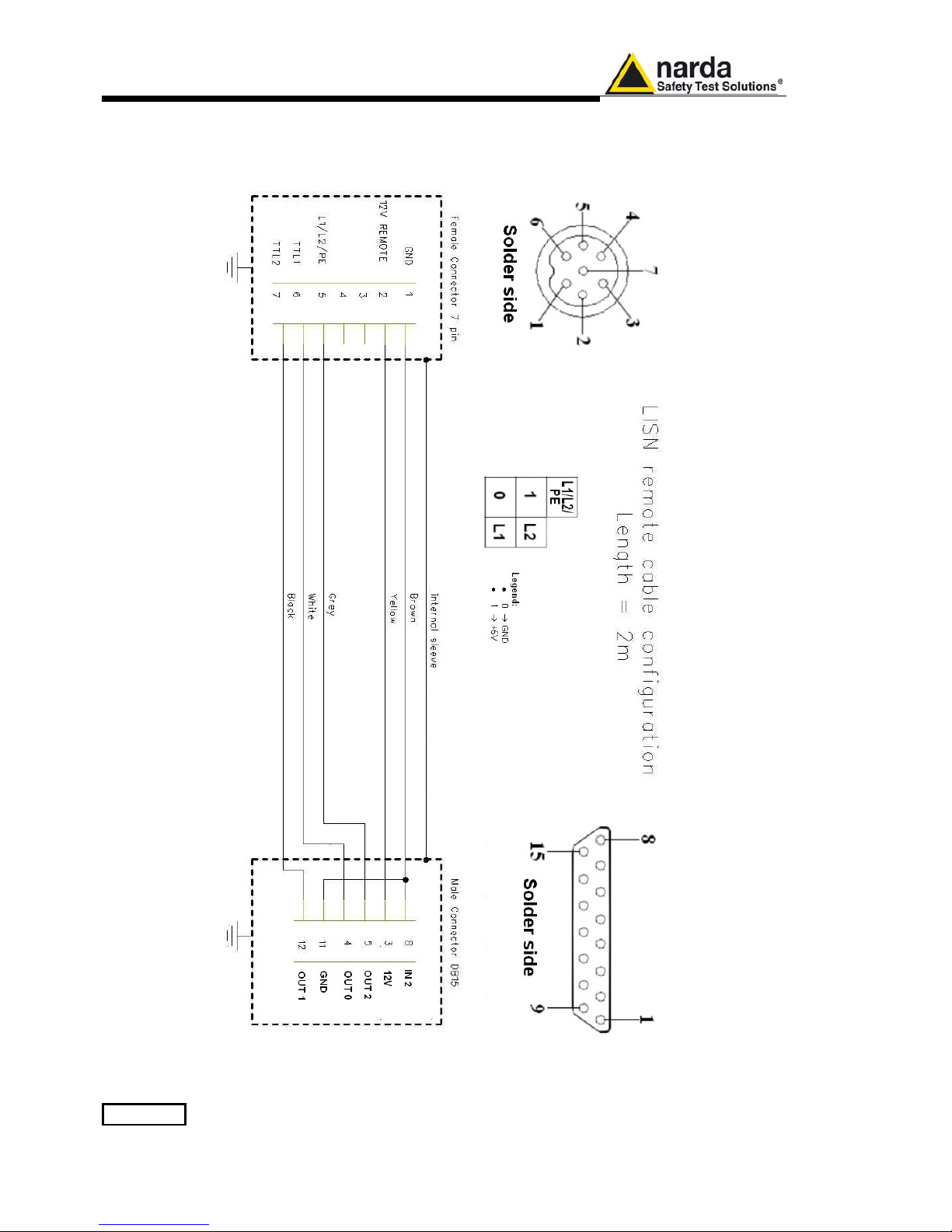
2-8 Installation
2.18 PMM L2-16
Remote Cable
configuration
for PMM 9010
The following figure shows the LISN remote cable pin configuration. The
cable can be requested to N
arda or arranged locally.
Fig. 2-4 PMM L2-16 remote cable configuration for PMM 9010
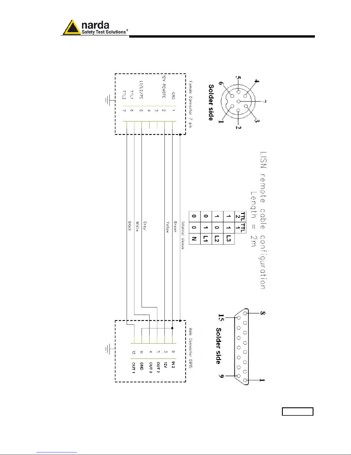
Installation 2-9
2.19 PMM L3-25
Remote Cable
configuration
for PMM 9010
The following figure shows the LISN remote cable pin configuration. The
cable can be requested to N
arda or arranged locally.
Fig. 2-5 PMM L3-25 remote cable configuration for PMM 9010

2-10 Installation
This page has been left blank intentionally

Setup and Panel Instructions 3-1
3 – Setup and Panel Instructions
3.1 Introduction
Press this function key in the main menu to enter in the Setup window,
which allows the Operator to set the global parameters of the receiver,
visualization options, etc.
The Setup function is divided into five, plus one, sub windows:
• Display
• Autocal
• Unit
• Rf Out
• Panel
Always use Esc button to return to the previous view/condition.
To scroll to the following page press the Left or Right Arrow key.
3.2 Display
The Display setup has four function keys:
• Inverse: to reverse the text and background colors;
• Style: to switch between font style 0 and font style 1;
• Key border: to choose the style of the key borderlines between three
different possibilities;
• Contrast / Back Light (toggle switch): to adjust the backlight and
contrast settings by the rotary knob.
Fig. 3-1 Display setting
Document 9010EN-81037-2.57 - © NARDA 2018

3-2 Setup and Panel Instructions
3.3 Autocal
Pressing the Autocal button PMM 9010 starts performing its automatic
self-calibration, using the internal precise tracking generator as a
reference.
The connection between the internal tracking generator and the input of
the receiver is done automatically inside the instrument.
To interrupt the self-calibration press the key Abort.
When the self-calibration is successfully finished a message is displayed:
In order to avoid any possible external influence, it is suggested to
disconnect all cables from the PMM 9010 RF ports during the selfcalibration process.
It is strongly recommended that the User launches the self-calibration
every now and then, and every time the instrument is used in
temperature-limit conditions.

Setup and Panel Instructions 3-3
3.4 Unit
Entering in the Unit menu it is possible to change the indicated unit used to
display the measured levels.
The available units are dBµV and dBm.
In a 50 Ohm system the relationship between dBm and dBμV is:
dBμV = dBm + 107
i.e., 0 dBm (1 mW) = 107 dBμV
3.5 RF OUT
The tracking generator is an internal, high stability and accuracy, 50 Ohm
RF generator ranging from 10 Hz to 50 MHz.
Activating the Tracking On function the generator is always tuned at the
same PMM 9010 measurement frequency and scans the range together
with the receiver. This is the standard way a tracking generator works in all
spectrum analyzers.
If the Tracking On function is disabled, the generator becomes a CW signal
source tuned at the frequency set under the RF OUT Freq window.
As usual, to set a given frequency it is therefore enough to edit the value
with the soft keys and the left and right arrows, confirming the selections
entering the units value (kHz, MHz or GHz).
Pressing 0 as the first figure the decimal dot appears automatically.
In both operating modes (tracking or fixed frequency) the output level can
be set between 60,0 and 90,0 dBµV with 0,1dB steps using the RF OUT
Level button.
If a higher or lower level is needed, the User shall adopt either an external
amplifier or an external attenuator.
The tracking generator is extremely useful for several applications: first of
all it is essential to calibrate the receiver itself thanks to the automatic
internal routines specifically developed to this extent, then it can also be
used to transform the PMM 9010 in a scalar network analyzer, helping a lot
in designing and testing RF filters, active stages and a lot of other circuits.
3.6 Panel
The Panel function allows the User to store up to 2 different setups that
can be recalled any time.
Pressing Save #1 or Save #2 the actual setup is stored in the internal
memory; with the two Recall buttons the corresponding setup is loaded to
the receiver.
Please remember each time one of the Save buttons is pressed, the stored
set-up is overwritten by the new one: the saved setups are therefore kept
memorized in the receiver until a new set-up is stored in the same
memory.
The Default button can be used to load a default standard setup saved
into the memory at the factory.

3-4 Setup and Panel Instructions
3.7 RS 232 (Speed)
Pressing the Left or the Right Arrow key, inside the Setup menu, the
second page appears. In the second page is the RS 232 Port speed
setting function.
Here it is possible to set the bit rate of the RS 232 serial port which
connector is located on the rear panel.
The actual setting is always shown between the parenthesis and it is
possible to choose between 9600, 38400 and 115200 bps.
The default speed, that is the one to be used for standard communication,
is 115200.
In case an optional device (ex. GPIB interface) is to be connected to the
RS 232 port, refer to its operating manual to know the correct speed to be
selected.

Sweep Mode Operating Instructions 4-1
4 - Sweep Mode Operating Instructions
4.1 Introduction
The Sweep mode is used to operate the PMM 9010 as a powerful scanning
EMI receiver. To enter in this mode it’s enough to depress the Sweep soft
key on the main screen, and immediately the scan setup window pops up
and allows the operator to set the parameters for the scan. All the automatic
settings (RBW, frequency step, etc.) refer to the CISPR standard.
Fig. 4-1 Sweep
As for the Analyzer operating mode, all the relevant information are reported
on the screen.
From the upper left corner, the User can see if the Preselector is ON or OFF;
if the Preamplifier is ON or OFF; which detector is in use and the relevant
hold time; if the function “Smart Detector” is activated and which one; if the
input attenuation is Automatic or Manual and the set attenuation and if the
Minimum attenuation is 10 dB or 0dB.
Just above the graph there is on the left the Reference level. During the
scan, in the center above the graph the actual frequency measured and/or
any other relevant operation (e.g. FFT, etc.).
Below the graph the start and the stop frequency, and loaded limits, if any.
When the sweep has been executed, on the bottom of the screen the most
important sweep parameters are repeated.
If the graph has been loaded from the memory, just below the start
frequency there is the symbol # followed by the memory position loaded
(position number 2 in figure 4-1).
Please note that the information in the upper part above the graph refers to
the next sweep to be done, while the information in the lower part, below the
graph, concerns to the actual displayed data.
Thanks to its digital architecture and to the clever design, the PMM
9010 receiver can make very fast measurements in the lower CISPR
band using the 200 Hz filter, yet maintaining full compliance to the
standards even in this very difficult condition.
Document 9010EN-81037-2.57 - © NARDA 2018
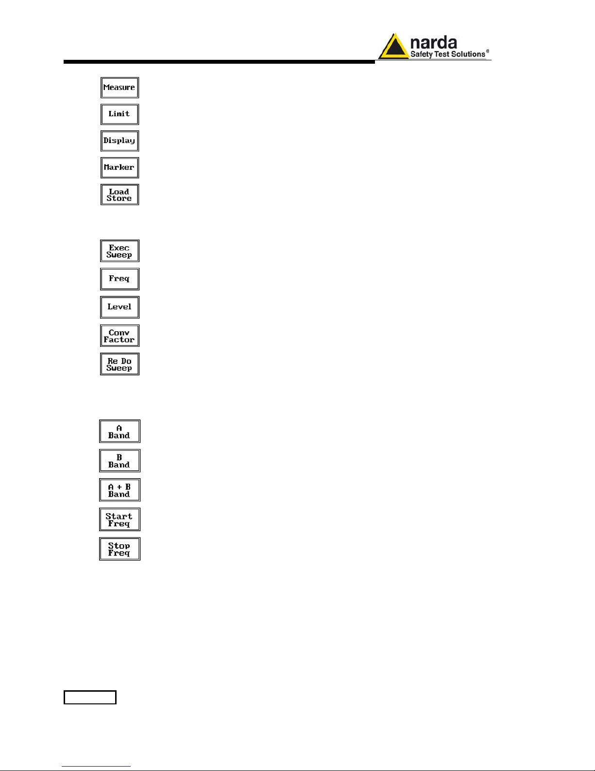
4-2 Sweep Mode Operating Instructions
The Sweep mode function is divided into five sub windows:
• Measure
• Limit
• Display
• Marker
• Load Store
Always use Esc button to return to the previous view/condition.
4.2 Measure
The Measure button is used to set the scan parameters and to run the
sweep.
After having chosen the frequency band and set all the other parameters it is
possible to run the measurement scan simply touching the Exec Sweep
button.
To make subsequent sweeps with the same setting parameters, simply
press ReDo Sweep. This key is particularly useful after having loaded a
previously stored track (see 4.6), as with the Re Do Sweep the original
settings are kept for the new measurement: it is extremely easy to make
comparisons, for example, before and after a modification of the EUT.
Once the scan starts, it can be stopped at any time during the execution by
the Stop function key that appears during the scan.
4.2.1 Frequency
The Frequency menu features five function buttons:
Pressing A Band the receiver will be set to scan the 9 - 150 kHz frequency
band. The definition of band A is a given in CISPR.
Pressing B Band the receiver will be set to scan the 0,15 - 30 MHz
frequency band. The definition of band B is a given in CISPR.
Pressing A + B Band the receiver will be set to scan the entire band from 9
kHz to 30 MHz.
Using these automatic band settings, the Frequency Step and Resolution
Bandwidth are set automatically according to CISPR standard requirement.
The Start and Stop frequency buttons can be used to set any frequency
interval for the measurement; to enter the frequency values press the
corresponding function keys.
Pressing either one of these 2 keys the figures 0, 1, 2, 3, and 4 are
selectable at first; with the right arrow key it is possible to select the figures
from 5 to 9, and pressing again the right arrow key the units kHz, MHz and
GHz becomes accessible, as well as the decimal dot and the Back Space.
The left arrow key can be used as well to move back and forth from one
screen to the other. Pressing 0 as the first figure the decimal dot appears
automatically.
To set a given frequency it is therefore enough to edit the value with the soft
keys and the left an right arrows, confirming the selections entering the units
value (kHz, MHz or GHz).
The figures entered appear in a small window just below the graph and the
default unit is MHz.

Sweep Mode Operating Instructions 4-3
4.2.2 Level
The Level function has 5 sub-menus, each one with several options..
Pressing the Display button it is possible to set two parameters: the
visualized Dynamic range (chosen between 80, 100 and 120dB) and the
Reference Level, that can be increased or reduced by steps of 5dB within
the range +80 dBμV to 135 dBμV (-25 to +30 dBm).
The Input button opens a submenu which is dedicated to the setting of the
input attenuator and to switch on-off the built-in preamplifier.
The PMM 9010 receiver takes automatically into account the settings of all
the Input parameters and always displays the correct value of the level. The
User is not required to make any correction to the readings.
4.2.2.1 Input:
Attenuators and
preamplifier
Being entered in the Input submenu, to increase or decrease the attenuation
at the input, press Att + or Att -, and for each touch the attenuation is
increased or decreased of 5 dB (preset value). Depressing either one of
these keys force the receiver in manual attenuation.
When the input attenuation is 0dB (condition that can be achieved only if the
Minimum Attenuation is set to 0 dB as well), the yellow led to the left of the
input BNC connector is ON and indicates a warning status.
The Min Att button acts as a toggle switch: it selects or deselects the
minimum attenuation of 10 dB. When the minimum attenuation is selected,
the attenuator – doesn’t matter if in automatic or in manual condition cannot be lowered under 10 dB.
Unless specifically required by the test conditions, do not remove the
minimum attenuation of 10 dB.
With the Preamp key it is possible to insert or exclude the built-in low noise
preamplification of 20 dB.
The internal 20 dB preamplifier can be used when very weak signals have to
be investigated. As already mentioned, with the preamplifier ON the receiver
takes automatically care of the 20 dB gain when measuring the signals.
The Att Auto button is used to switch from the two conditions of manual or
automatic attenuation setting.
Please note that the switching of the attenuators is relatively noisy and you
can perceive it distinctly with a “click” for each switch operation.
In case an OVERLOAD indication occurs it is necessary to add an external
attenuator to carry on the measurement without overpassing the declared
limit for continuous power or spectral density.
Using 0 dB attenuation PMM 9010 has no input protection.
This is a potentially dangerous condition for the input stage of the
receiver.
Use 0 dB attenuation only if you are very sure that your input signal is
less than 0.5 Vpp (or 106 dBμV).
Before to apply an unknown signal to PMM 9010 receiver, use an
oscilloscope or a wide band RF voltmeter to measure it. In any case set
Min. ATT at 10 dB and select the maximum available attenuation with
preamplifier OFF.
If needed, add an external coaxial attenuator on the input signal line.
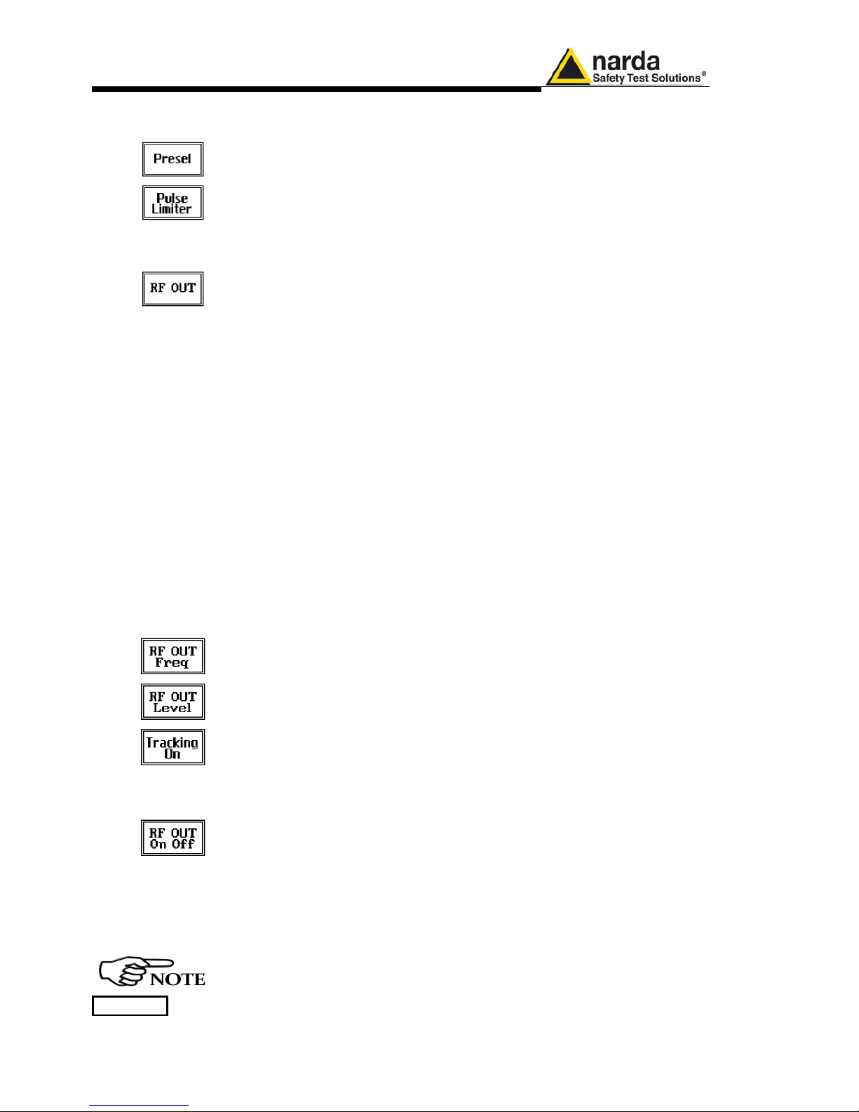
4-4 Sweep Mode Operating Instructions
4.2.2.2 Misc
Under the Miscellanea functions menu it is possible to activate or exclude
the Preselector filters, the Pulse Limiter, and also to enter in the Tracking
generator menu pressing the RF OUT button.
The Preselector is composed by a group of filters automatically selected by
the PMM 9010 while it is sweeping or anyway measuring. The aim of the
preselector is to reduce the amount of out-of-band energy entering in the
receiver, thus helping a lot in reducing intermodulation problems and similar
undesired behaviors.
It can be set either ON or OFF with the associated button, and normally it
should be always enabled.
On the top left corner of the screen the symbol “Off” or “On” will be
displayed.
The Pulse Limiter is a very useful device to protect the input of the receiver
from transient overvoltages. Doing conducted emission tests, quite often
there are conducted disturbances (usually associated to switching
operations in the EUT or along the line under test) which are too high and
that propagates through the LISN up to the receiver. Sometime these
disturbances cannot be seen on the receiver because they are out of
measurement bandwidth, nevertheless the associate energy is high enough
to damage the input attenuator and/or the Analog-to-Digital Converter of the
PMM 9010 (the first mixer in a traditional receiver).
This pulse limiter has an integrated 10dB attenuator and a 30 MHz low-pass
filter.
When the Pulse Limiter is selected, on the upper part of the screen the
letters P.L. appear next the value of the Minimum Attenuation and the
reading on the receiver is automatically corrected for the attenuation factor
of the Pulse Limiter.
Pressing the RF OUT button the receiver enters the Tracking generator
menu.
.
4.2.2.2.1 Tracking
generator
The tracking generator is an internal, high stability and accuracy, 50 Ohm
RF generator ranging from 10 Hz to 50 MHz.
Activating the Tracking On function the generator is always tuned at the
same PMM 9010 measurement frequency and scans the range together
with the receiver. This is the standard way a tracking generator works in all
spectrum analyzers.
If the Tracking On function is disabled, the generator becomes a CW signal
source tuned at the frequency set under the RF OUT Freq window.
As usual, to set a given frequency it is therefore enough to edit the value
with the soft keys and the left an right arrows, confirming the selections
entering the units value (kHz, MHz or GHz).
Pressing 0 as the first figure the decimal dot appears automatically.
In both operating modes (tracking or fixed frequency) the output level can be
set between 60,0 and 90,0 dBµV with 0,1dB steps using the RF OUT Level
button.
If a higher or lower level is needed, the User shall adopt either an external
amplifier or an external attenuator.
The tracking generator is extremely useful for several applications: first of all
it is essential to calibrate the receiver itself thanks to the automatic internal
routines specifically developed to this extent, then it can also be used to
transform the PMM 9010 in a scalar network analyzer, helping a lot in
designing and testing RF filters, active stages and a lot of other circuits.
It is suggested to turn off the Generator to achieve the maximum
sensitivity.

Sweep Mode Operating Instructions 4-5
4.2.2.2 Detector
This menu allows the operator to select the most appropriate detector for
the test.
In Sweep mode the Peak, Average, RMS (Root Mean Square) and QuasiPeak detectors are available and can be selected via the appropriate button.
Hold time (ms)
The Hold Time (expressed in milliseconds) represents the time the receiver
uses to “take a snapshot” of the incoming signal and to measure it with the
chosen detector. When selecting a detector, the default hold time value is
automatically loaded, but in some cases this time is not appropriate, e.g.
when the interference signals have a low repetition rate. In this case the
PMM 9010 sees a high input signal and therefore tries to set the proper
attenuation automatically increasing the value or the input attenuators.
However, when the input attenuation is set the signal is gone, so the
receiver lowers the attenuation, but then a new peak arrives, and so on and
so forth.
On the other hand, if the Hold Time is too high the PMM 9010 cannot
properly follow the signals.
In this situation the Hold Time value should be manually set to find a correct
compromise.
To set the Hold Time to the lowest possible value (this value dynamically
depends from the measurement conditions), enter the figure 0; if a value
lower than the allowed is entered, the lowest possible value is automatically
selected.
The max. Hold Time that can be set is 30 sec (30.000 ms).
4.2.2.3 Smart Detector
The Smart Detector is an innovative special function implemented in the
PMM 9010 receiver with the purpose of reducing the test time and
increasing the productivity of the lab.
This function works only when at least one limit is loaded, therefore
remember to enable a limit to run the Smart detector function.
Selecting one out of the three Smart detectors the receiver will execute the
scan using at first the Peak detector and, if a peak value is found over the
selected limit minus a Margin set with the specific button, the reading is remeasured and displayed with the chosen (AVG, RMS or QPeak) detector.
Obviously this way of operation results in a much faster scan sweep and
moreover it immediately draws the attention of the test Engineer to the most
critical points. The limit associated to the Margin is displayed as a bold black
line and is automatically selected by the receiver depending which Smart
detector is chosen; for example, if a Smart QP is selected, the associated
QP limit line will be displayed as a bold black line.
The Smart RMS detector is disabled until a reference limit is defined by
CISPR.
It is immediately clear that this function is very useful to dramatically reduce
test time and increase the productivity of the test lab.
To deselect the Smart Detector function simply select a single detector.
The weighting time must be properly set in the Hold Time window to
allow the Smart detectors functions to operate as intended.
4-6 Sweep Mode Operating Instructions
4.2.3 Conversion factor
When using a transducer to make a measurement – a Voltage or Current
Probe, an Antenna, etc. – there is always the need to add to the measured
values the conversion factor of the transducer in use.
The Conversion factor may also take proper account of losses as cable loss,
attenuators added externally to the receiver, etc.
The PMM 9010 can handle these factors in an automatic way and directly
correct the readings.
The PMM 9010 can store in its internal non-volatile memory up to 4 different
correction factors, and use them one at a time when recalled.
However, the Conversion Factors shall be created and loaded via the PMM
9010 Software Utility.
Press the relevant button to load the conversion factor, and NONE to unload
it.
4.3 Limit
Each emission standard has one or more limits the User shall comply with.
The PMM 9010 receiver has the possibility to load and activate one limit with
a simple push of a button.
The preloaded standard limits refer to the most popular EMC emission
standards: CISPR22, CISPR14 and CISPR11.
Other limits – or any custom designed limit – can be created, managed,
selected and loaded through the PMM 9010 Software Utility running on a PC
(and the test, of course, shall be handled via the PC software).
These additional custom limits cannot be stored in the memory of the PMM
9010, but only in the one of the PC where the 9010SW Utility is running.
The limits are shown on the scan display and they appear like a thin black
line when the Smart Detector function is not enabled, while one of them
appears in bold black when the Smart Detector function is active.
By pressing the NONE button all limits are deactivated.
4.4 Display
Pressing the Display button it is possible to set two parameters: the
visualized Dynamic range (chosen between 80, 100 and 120dB) and the
Reference Level, that can be increased or reduced by steps of 5dB within
the range +80 dBμV to 135 dBμV (-25 to +30 dBm); see also 4.2.

Sweep Mode Operating Instructions 4-7
4.5 Marker
Selecting this function a Marker is immediately enabled, and it appears on
the screen as a small black pointing down arrow corresponding to the
highest reading; simultaneously a small window shows up in the bottom left
corner of the screen, indicating the actual frequency and level read by the
marker.
The Marker function is not a simple search for the highest readings on the
screen – it would be a useless exercise that would display a number of
points all grouped together – but it’s a true peak search that measures the
degree of variation of the signal: a peak is so classified only if it “pops-up”
from the adjacent signals with at least 5 dB difference in amplitude.
Following this criterion, if the measured signal is a flat line no peaks will be
found.
Selecting Highest X – where X represents the maximum number of markers
found by the receiver during its sweep – few more markers are added, each
one “diamond” shaped, defined as per the previous explanation.
The maximum number of markers available is 10.
By using arrow keys it is possible to quickly move on markers from higher
amplitude (left arrow) to lower amplitude (right arrow), i.e. if the highest is
selected, pressing the right arrow key the 2
nd
highest is selected, then
pressing again the same key the 3
rd
highest and so on and so forth.
It is also possible to use the rotary knob to move from a marker to the next
one.
The marker under analysis (main marker) is a black arrow pointing down,
the others are diamond shaped.
Pressing the Peak button the marker returns to the highest reading.
In order to make easier and faster the evaluation of the more noisy signals,
the User can now select either the Analyzer or the Tune function, entering
respectively into a spectrum analysis of main marker position or in the
manual mode evaluation of it. To operate this two conditions please refer to
the appropriate section of this Operating Manual.
In manual mode, i.e. having selected Tune on the main marker, it is possible
to navigate from one peak to the other just pressing the arrow keys, without
to come back to the Sweep display and remaining in manual mode.
This is another unique feature of PMM 9010 to improve the productivity of
the test lab and make easier the work of the test engineer.
The Marker Off exits from the marker function.

4-8 Sweep Mode Operating Instructions
4.6 Load Store
Pressing this key allows the User to have access to the memory of the
receiver and enables the storing up to a number of different
configurations/sweeps that depends on the parameters set on the receiver
(i.e. the number of measured points). For example, using standard CISPR
parameters it is possible to store up to 15 sweeps on the A+B band.
Each new scan will be stored in the first available memory position thanks to
the button Store #x, where x is the first available position. When all positions
are occupied by a scan, this function is disabled until one of the previous
scan is erased.
To load a stored trace, press the Load #x button until the proper scan is
displayed; to unload a trace select the Unload Trace button.
Please note that the Load function is scanning the memory in a circular way,
therefore all the occupied memory positions are shown in sequence. When
the key shows “Load #4”, it means the trace #3 is displayed and that the #4
will be loaded after the key is pressed, and so on and so forth.
To erase a trace, press the Erase#x button.
Due to the structure of the memory, it is possible to erase only the latest
stored memory, with a sequence “LIFO” (Last In First Out), therefore after
having erased the #x, the #(x-1) will be the trace to be erased. With
reference to the example at the left, the last stored trace is the #4, and it is
the first that will be erased. After that, the key will show “Erase #3”, and so
on and so forth.
A more advanced trace management could be done using the PMM 9010
Software Utility.
Turn Off the tracking generator, if it is not used, while you are in Scan
Mode.
This prevents interferences and the measurements are more clean and
accurate.
4.7 Ultra Fast FFT scan
The Ultra Fast FFT (Fast Fourier Transform), as described at §1.11,
provides a “snapshot” of the whole band in just one second, what is useful
for a more comprehensive analysis in case the disturbance to be evaluated
is somehow intermittent and with an irregular repetition rate.
To activate this feature few settings have to be manually performed at first,
as per the following:
- Peak detector
- ≤ 50ms Hold Time
- Band A sweep.
Once all these conditions are satisfied, the Sweep is performed in really “one
second”, what is very useful to soon realize overall behaviour of EUTs in a
debugging phase, saving time and making it possible even in those cases
where the EUT cannot stay ON for a long time without getting damaged
(small electric motors, etc.)
Later on will be then possible to make the full-compliant Quasi-Peak
evaluation of all the frequencies of interest after the measurements will been
taken.
During such FFT analysis the PMM 9010 makes use of internal standard
Gaussian filters still in compliance with the norms.
When using the Smart Detector under ultra fast FFT scan, the
maximum number of investigated frequencies is 20.
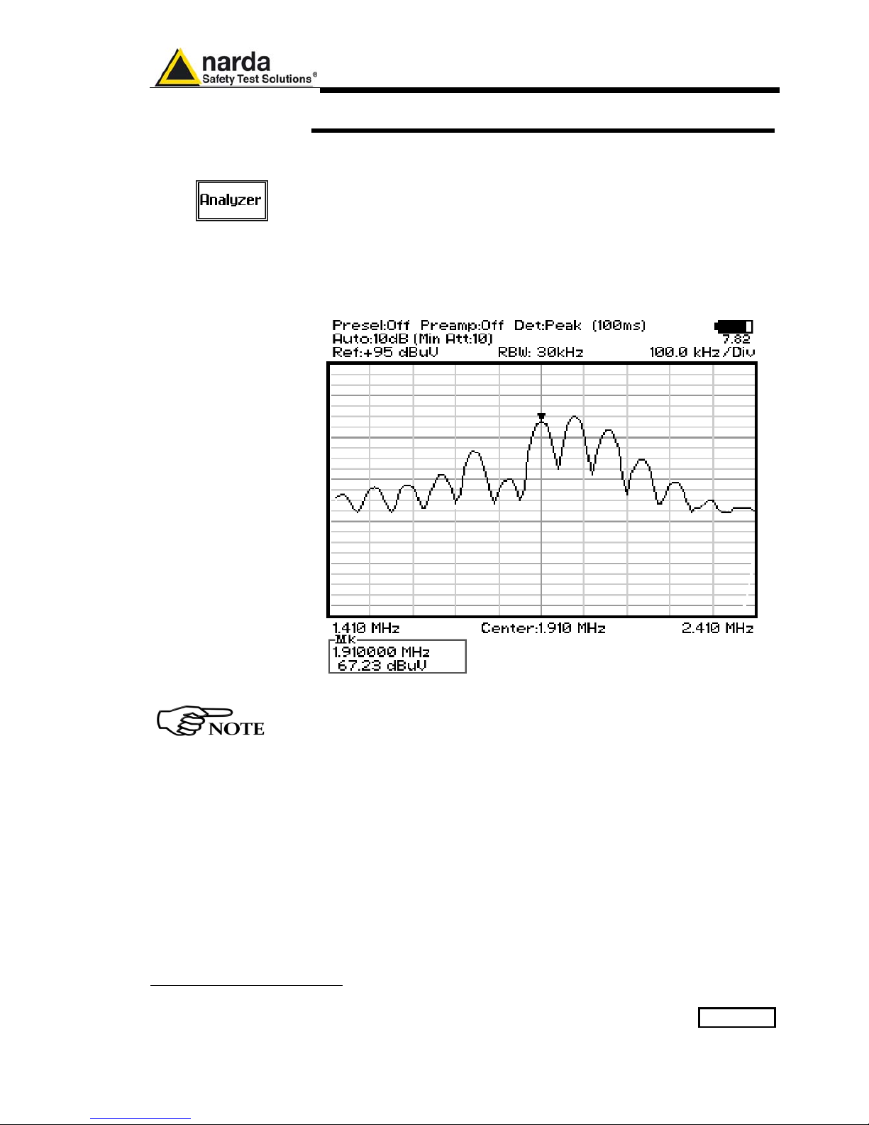
Analyzer Mode Operating Instructions 5-1
5 - Analyzer Mode Operating Instructions
5.1 Introduction
To enter in the ANALYZER Mode it’s enough to depress the Analyzer soft
key on the main screen.
In this mode the receiver works as a powerful Spectrum Analyzer and the
display shows the "spectrum analysis" (span max 30 MHz) in the frequency
domain of a signal tuned at a given frequency.
The analysis is done at the selected span frequency.
Using the marker facility the User can accomplish a very accurate
measurement of the signals either in frequency as well as in level.
Entering Analyzer Mode from the main menu, the display will look like the
following:
Fig. 5-1 Spectrum
The SPAN per division is automatically managed by the equipment and
divided by 10. The minimum SPAN is 100Hz per division.
On the screen of the Analyzer Mode all the relevant information are
reported.
From the upper left corner, the User can see if the Preselector is ON or OFF;
if the Preamplifier is ON or OFF; which detector is in use and the relevant
hold time; if the input attenuation is Automatic or Manual and the set
attenuation and if the Minimum attenuation is 10 dB or 0dB.
Just above the graph, from left to right, there is the Reference level, the
Resolution bandwidth and the span value.
Below the graph the start, center and stop frequency.
The bottom left corner is dedicated to the marker indication, with actual
frequency and level of the marker.
Document 9010EN-81037-2.57 - © NARDA 2018
5-2 Analyzer Mode Operating Instructions
The Spectrum mode function is divided into five sub windows:
• Frequency
• Resolution Bandwidth
• Level
• Marker
• Wide Mode
The fifth button is used to change the spectrum view to wide screen mode,
as shown in the picture 5-1, and with the Esc button the original view can be
restored.
Always use Esc button to return to the previous view/condition.
5.2 Frequency
Allows the User to set the tuning frequency and also the Span.
The Center frequency of the Spectrum window can be directly edited into
the window or set by the arrow buttons or by the rotary knob, which
frequency steps are set under the Manual mode.
Depressing the Center button the figures 0, 1, 2, 3, and 4 are selectable;
with the right arrow key it is possible to select the figures from 5 to 9, and
pressing again the right arrow key the units kHz, MHz and GHz becomes
accessible, as well as the decimal dot and the Back Space. The left arrow
key can be used as well to move back and forth from one screen to the
other. Pressing 0 as the first figure the decimal dot appears automatically.
To set a given frequency it is therefore enough to edit the value with the soft
keys and the left an right arrows, confirming the selections entering the units
value (kHz, MHz or GHz).
The figures entered appear in a small window just below the graph and the
default unit is MHz, so 100 kHz = 0,1 MHz; 10 kHz = 0,01 MHz;
1 kHz = 0,001 MHz and 100 Hz = 0,0001 MHz.
Using the Start and Stop buttons it is possible to select any start and stop
value in the frequency range 10 Hz to 30 MHz band.
Another method for setting the frequency is to enter the Center frequency
and the appropriate Span.
In this mode of operation the frequency step (spectrum resolution) is set
automatically, therefore it cannot be changed manually.
In order to better analyze the signals close to the ends of the band and
see them properly with any of the applicable filters, the receiver is able
to go lower than 10 Hz and higher than 30 MHz.
The actual minimum frequency that can be displayed on the screen is 0
Hz, the maximum is 32 MHz.

Analyzer Mode Operating Instructions 5-3
5.3 RBW
The Resolution Bandwidth command is used to select the bandwidth of
the measuring filter. Seven bandwidth filters are available:
• 200 Hz CISPR 16 shaped at -6dB
• 9 kHz CISPR 16 shaped at -6dB
• 3 kHz at -3dB
• 10 kHz at -3dB
• 30 kHz at -3dB
• 100 kHz at -3dB
• 300 kHz at -3dB
The three larger filters are selectable from the first RBW screen, and
pressing the More RBW button it is possible to select all the other filters.
These filters are mathematically modeled using FIR (Finite Impulse
Response) technique and they are exactly as required by the standards.
More filters will be available as an option for specific applications, e.g. to
cover Military Standards requirements, etc.
5.4 Level
The Level function has 5 sub-menus, each one with several options.
Pressing the Display button it is possible to set two parameters: the
visualized Dynamic range (chosen between 80, 100 and 120dB) and the
Reference Level, that can be increased or reduced by steps of 5dB within
the range +60 dBµV to 130 dBµV (-45 to 25 dBm); in operating modes
Analyzer and Manual the min.-max. values of the reference level are in
function of the input attenuator and preamplifier settings.
The Input button opens a submenu which is dedicated to the setting of the
input attenuator and to switch on-off the built-in preamplifier.
The PMM 9010 receiver takes automatically into account the settings of all
the Input parameters and always displays the correct value of the level. The
User is not required to make any correction to the readings.
5.4.1 Input: Attenuators
and preamplifier
Being entered in the Input submenu, to increase or decrease the attenuation
at the input, press Att + or Att -, and for each touch the attenuation is
increased or decreased of 5 dB (preset value). Depressing either one of
these keys force the receiver in manual attenuation.
When the input attenuation is 0dB (condition that can be achieved only if the
Minimum Attenuation is set to 0 dB as well), the yellow led to the left of the
input BNC connector is ON and indicates a warning status.
The Min Att button acts as a toggle switch: it selects or deselects the
minimum attenuation of 10 dB. When the minimum attenuation is selected,
the attenuator – doesn’t matter if in automatic or in manual condition cannot be lowered under 10 dB.
Unless specifically required by the test conditions, do not remove the
minimum attenuation of 10 dB.
With the Preamp key it is possible to insert or exclude the built-in low noise
preamplification of 20 dB.
The internal 20 dB preamplifier can be used when very weak signals have to
be investigated. As already mentioned, with the preamplifier ON the receiver
takes automatically care of the 20 dB gain when measuring the signals.
The Att Auto button is used to switch from the two conditions of manual or
automatic attenuation setting.
Please note that the switching of the attenuators is relatively noisy and you
can perceive it distinctly with a “click” for each switch operation.

5-4 Analyzer Mode Operating Instructions
Using 0 dB attenuation PMM 9010 has no input protection.
This is a potentially dangerous condition for the input stage of the
receiver.
Use 0 dB attenuation only if you are very sure that your input signal is
less than 0.5 Vpp (or 106 dBμV).
Before to apply an unknown signal to PMM 9010 receiver, use an
oscilloscope or a wide band RF voltmeter to measure it. In any case set
Min. ATT at 10 dB and select the maximum available attenuation with
preamplifier OFF.
If needed, add an external coaxial attenuator on the input signal line.
5.4.2 OVER RANGE
Message
An Over Range indication will automatically appear on the screen to inform
the User that the levels of the measured signals in the spectrum window is
too high: to avoid measuring errors and even damages to the receiver a
higher attenuation shall be set.
5.4.3 Misc
Under the Miscellanea functions menu it is possible to activate or exclude
the Preselector filters, the Pulse Limiter, and also to set the Tracking
Generator.
The Preselector is composed by a group of filters automatically selected by
the PMM 9010 while it is sweeping or anyway measuring. The aim of the
preselector is to reduce the amount of out-of-band energy entering in the
receiver, thus helping a lot in reducing intermodulation problems and similar
undesired behaviors.
In Analyzer mode the preselector is available only if the entire span falls in
one filter band (see the main specification in chapter 1 to verify the
frequency bands). In this situation on the display it will be shown:
Preselector ON. If the span is larger then one filter only, on the display the
symbol *** will appear instead.
It can be set either ON or OFF with the associated button, and normally it
should be always enabled.
On the top left corner of the screen the symbol “Off” or “On” will be
displayed.
The Pulse Limiter is a very useful device to protect the input of the receiver
from transient overvoltages. Doing conducted emission tests, quite often
there are conducted disturbances (usually associated to switching
operations in the EUT or along the line under test) which are too high and
that propagates through the LISN up to the receiver. Sometime these
disturbances cannot be seen on the receiver because they are out of
measurement bandwidth, nevertheless the associate energy is high enough
to damage the input attenuator and/or the Analog-to-Digital Converter of the
PMM 9010 (the first mixer in a traditional receiver).
This pulse limiter has an integrated 10dB attenuator and a 30 MHz low-pass
filter.
When the Pulse Limiter is selected, on the upper part of the screen the
letters P.L. appear next the value of the Minimum Attenuation and the
reading on the receiver is automatically corrected for the attenuation factor
of the Pulse Limiter.
Pressing the RF OUT button the receiver enters the Tracking generator
menu.
Analyzer Mode Operating Instructions 5-5
5.4.3.1 Tracking
generator
The tracking generator is an internal, high stability and accuracy, 50 Ohm
RF generator ranging from 10 Hz to 50 MHz.
Activating the Tracking On function the generator is always tuned at the
same PMM 9010 measurement frequency and scans the range together
with the receiver. This is the standard way a tracking generator works in all
spectrum analyzers.
If the Tracking On function is disabled, the generator becomes a CW signal
source tuned at the frequency set under the RF OUT Freq window.
As usual, to set a given frequency it is therefore enough to edit the value
with the soft keys and the left an right arrows, confirming the selections
entering the units value (kHz, MHz or GHz).
Pressing 0 as the first figure the decimal dot appears automatically.
In both operating modes (tracking or fixed frequency) the output level can
be set between 60,0 and 90,0 dBµV with 0,1dB steps using the RF OUT
Level button.
If a higher or lower level is needed, the User shall adopt either an external
amplifier or an external attenuator.
The tracking generator is extremely useful for several applications: first of
all it is essential to calibrate the receiver itself thanks to the automatic
internal routines specifically developed to this extent, then it can also be
used to transform the PMM 9010 in a scalar network analyzer, helping a lot
in designing and testing RF filters, active stages and a lot of other circuits.
It is suggested to turn off the Generator to achieve the maximum
sensitivity.
5.4.4 Detector
This menu allows the Operator to select the most appropriate detector for
the test.
In Analyzer mode the Peak, Average and RMS (Root Mean Square)
detectors are available and can be selected via the appropriate button.
Hold time
The Hold Time (expressed in milliseconds) represents the time the receiver
uses to “take a snapshot” of the incoming signal and to measure it with the
chosen detector. When selecting a detector, the default hold time value is
automatically loaded, but in some cases this time is not appropriate, e.g.
when the interference signals have a low repetition rate. In this case the
PMM 9010 sees a high input signal and therefore tries to set the proper
attenuation automatically increasing the value or the input attenuators.
However, when the input attenuation is set the signal is gone, so the
receiver lowers the attenuation, but then a new peak arrives, and so on
and so forth..
On the other hand, if the Hold Time is too high the PMM 9010 cannot
properly follow the signals.
In this situation the Hold Time value should be manually set to find a
correct compromise.
To set the Hold Time to the lowest possible value (this value dynamically
depends from the measurement conditions), enter the figure 0; if a value
lower than the allowed is entered, the lowest possible value is
automatically selected.
The max. Hold Time that can be set is 30 sec (30.000 ms).

5-6 Analyzer Mode Operating Instructions
5.4.5 Conversion factor
When using a transducer to make a measurement – a Voltage or Current
Probe, an Antenna, etc. – there is always the need to add to the measured
values the conversion factor of the transducer in use.
The Conversion factor may also take proper account of losses as cable
loss, attenuators added externally to the receiver, etc.
The PMM 9010 can handle these factors in an automatic way and directly
correct the readings.
The PMM 9010 can store in its internal non-volatile memory up to 4
different correction factors, and use them one at a time when recalled.
However, the Conversion Factors shall be created and loaded via the
PMM 9010 Software Utility.
Press the relevant button to load the conversion factor, and NONE to
unload it.
5.5 Marker
With this command the Marker function can be enabled.
Switching ON the marker it appears on the screen as a small black
pointing down arrow, and simultaneously a small window shows up in the
bottom left corner of the screen, indicating the actual frequency and level
read by the marker.
Pressing the Peak button the marker will automatically move to the highest
signal found in the span range in that given moment, and with the help of
the Center button the frequency selected by the marker becomes the
center frequency on the screen, making very easy any signal analysis.
5.6 ESC
This button allows to return to the previous view or condition.

Manual Mode Operating Instructions 6-1
6 - Manual Mode Operating Instructions
6.1 Introduction
The MANUAL mode is a very useful feature to manually control the
receiver and to deeply investigate electrical signals modifying the
parameters of receiver exactly as per the needs of the Test Engineer.
It is possible, for example, to observe the signals exceeding the limits
frequency by frequency; evaluating their levels measured simultaneously
with 4 different detectors (Peak, QuasiPeak, Average and RMS); listening
to them after a demodulation, etc.
To enter in .Manual Mode press the key in the main menu, and
immediately the first Manual window opens as follow.
Fig. 6-1 Manual
In manual mode the levels corresponding to the detectors in use are
displayed both in analogue and in digital format, and exactly as for the
other operating modes, all the relevant information are reported on the
screen.
From the upper left corner, the User can see if the Preselector is ON or
OFF; if the Preamplifier is ON or OFF; the resolution bandwidth, the
longest hold time associated to the detectors in use; if the input attenuation
is Automatic or Manual and the set attenuation and if the Minimum
attenuation is 10 dB or 0dB; if there a demodulation and the level of the
volume, represented by a small black bar.
Then there are three or fours vertical bars representing the detectors and
indicating in analogue and digital (the figures below each bar) the level
measured; on top of the bars the relevant detector, the unit in use and the
tuned frequency. The analogue scale of the analogue bars is set
automatically by the receiver.
Document 9010EN-81037-2.57 - © NARDA 2018
6-2 Manual Mode Operating Instructions
The Manual mode function has five sub windows:
• Frequency
• Level
• Resolution Bandwidth
• Hold Time
• Demodulation
Always use Esc button to return to the previous view/condition.
6.2 Frequency
Under this menu it is possible to set the tuning frequency and also the
knob and the arrow keys steps.
The center Frequency of the reading can be directly edited into the Tune
window or set by the left and right arrow buttons or by rotating the knob.
The figures entered appear in a small window just below the graph and the
default unit is MHz.
Having selected Tune, the figures 0, 1, 2, 3, and 4 are selectable at first;
with the right arrow key it is possible to select the figures from 5 to 9, and
pressing again the right arrow key the units kHz, MHz and GHz becomes
accessible, as well as the decimal dot and the Back Space. The left arrow
key can be used as well to move back and forth from one screen to the
other. Pressing 0 as the first figure the decimal dot appears automatically.
To set a given frequency it is therefore enough to edit the value with the
soft keys and the left an right arrows, confirming the selections entering the
units value (kHz, MHz or GHz).
If Knob is selected, the small window below the bars indicate the step
which is going to be selected. After having fixed the step size, rotate the
know and tune the desired frequency.
If Arrow is selected, the small window below the bars indicate the step
which is going to be selected. After having fixed the step size, press the left
and the right arrow keys to decrease or increase the frequency by the
selected step.
6.3 Level
The Level function has 4 sub-menus.
Pressing the Display button it is possible to set two parameters: the
visualized Dynamic range (chosen between 80, 100 and 120dB) and the
Reference Level, that can be increased or reduced by steps of 5dB within
the range +60 dBµV to 130 dBµV (-45 to 25 dBm); in operating modes
Analyzer and Manual the min.-max. values of the reference level are in
function of the input attenuator and preamplifier settings.
The Input button opens a submenu which is dedicated to the setting of the
input attenuator and to switch on-off the built-in preamplifier.
The PMM 9010 receiver takes automatically into account the settings of all
the Input parameters and always displays the correct value of the level.
The User is not required to make any correction to the readings.

Manual Mode Operating Instructions 6-3
6.3.1 Input: Attenuator
and preamplifier
Being entered in the Input submenu, to increase or decrease the attenuation
at the input, press Att + or Att -, and for each touch the attenuation is
increased or decreased of 5 dB (preset value). Depressing either one of
these keys force the receiver in manual attenuation.
When the input attenuation is 0dB (condition that can be achieved only if the
Minimum Attenuation is set to 0 dB as well), the yellow led to the left of the
input BNC connector is ON and indicates a warning status.
The Min Att button acts as a toggle switch: it selects or deselects the
minimum attenuation of 10 dB. When the minimum attenuation is selected,
the attenuator – doesn’t matter if in automatic or in manual condition cannot be lowered under 10 dB.
Unless specifically required by the test conditions, do not remove the
minimum attenuation of 10 dB.
With the Preamp key it is possible to insert or exclude the built-in low noise
preamplification of 20 dB.
The internal 20 dB preamplifier can be used when very weak signals have to
be investigated. As already mentioned, with the preamplifier ON the receiver
takes automatically care of the 20 dB gain when measuring the signals.
The Att Auto button is used to switch from the two conditions of manual or
automatic attenuation setting.
Please note that the switching of the attenuators is relatively noisy and you
can perceive it distinctly with a “click” for each switch operation.
Using 0 dB attenuation PMM 9010 has no input protection.
This is a potentially dangerous condition for the input stage of the
receiver.
Use 0 dB attenuation only if you are very sure that your input signal is
less than 1 V (or 120 dBμV).
Before to apply an unknown signal to PMM 9010 receiver, use an
oscilloscope or a wide band RF voltmeter to measure it. In any case set
Min. ATT at 10 dB and select the maximum available attenuation with
preamplifier OFF.
If needed, add an external coaxial attenuator on the input signal line.
In case an OVERLOAD indication occurs it is necessary to add an
external attenuator to carry on the measurement without overpassing
the declared limit for continuous power or spectral density.
6.3.2 Misc
Under the Miscellaneous functions menu it is possible to activate or
exclude the Preselector filters, the Pulse Limiter, and also to set the
Tracking generator.
The Preselector is composed by a group of filters automatically selected by
the PMM 9010 while it is sweeping or anyway measuring. The aim of the
preselector is to reduce the amount of out-of-band energy entering in the
receiver, thus helping a lot in reducing intermodulation problems and similar
undesired behaviors.
It can be set either ON or OFF with the associated button, and normally it
should be always enabled.
On the top left corner of the screen the symbol “Off” or “On” will be
displayed.
6-4 Manual Mode Operating Instructions
The Pulse Limiter is a very useful device to protect the input of the
receiver from transient overvoltages. Doing conducted emission tests,
quite often there are conducted disturbances (usually associated to
switching operations in the EUT or along the line under test) which are too
high and that propagates through the LISN up to the receiver. Sometime
these disturbances cannot be seen on the receiver because they are out of
measurement bandwidth, nevertheless the associate energy is high
enough to damage the input attenuator and/or the Analog-to-Digital
Converter of the PMM 9010 (the first mixer in a traditional receiver).
This pulse limiter has an integrated 10dB attenuator and a 30 MHz lowpass filter.
When the Pulse Limiter is selected, on the upper part of the screen the
letters P.L. appear next the value of the Minimum Attenuation and the
reading on the receiver is automatically corrected for the attenuation factor
of the Pulse Limiter.
Pressing the RF OUT button the receiver enters the Tracking generator
menu.
The tracking generator is an internal, high stability and accuracy, 50 Ohm
RF generator ranging from 10 Hz to 50 MHz.
Activating the Tracking On function the generator is always tuned at the
same PMM 9010 measurement frequency and scans the range together
with the receiver. This is the standard way a tracking generator works in all
spectrum analyzers.
If the Tracking On function is disabled, the generator becomes a CW signal
source tuned at the frequency set under the RF OUT Freq window.
As usual, to set a given frequency it is therefore enough to edit the value
with the soft keys and the left an right arrows, confirming the selections
entering the units value (kHz, MHz or GHz).
Pressing 0 as the first figure the decimal dot appears automatically.
In both operating modes (tracking or fixed frequency) the output level can
be set between 60,0 and 90,0 dBµV with 0,1dB steps using the RF OUT
Level button.
If a higher or lower level is needed, the User shall adopt either an external
amplifier or an external attenuator.
The tracking generator is extremely useful for several applications: first of
all it is essential to calibrate the receiver itself thanks to the automatic
internal routines specifically developed to this extent, then it can also be
used to transform the PMM 9010 in a scalar network analyzer, helping a lot
in designing and testing RF filters, active stages and a lot of other circuits.
It is suggested to turn off the Generator to achieve the maximum
sensitivity.

Manual Mode Operating Instructions 6-5
6.4 RBW
The Resolution Bandwidth command is used to select the bandwidth of
the measuring filter. Seven bandwidth filters are available:
• 200 Hz CISPR 16 shaped at -6dB
• 9 kHz CISPR 16 shaped at -6dB
• 3 kHz at -3dB
• 10 kHz at -3dB
• 30 kHz at -3dB
• 100 kHz at -3dB
• 300 kHz at -3dB
The three larger filters are selectable from the first RBW screen, and
pressing the More RBW button it is possible to select all the other filters.
These filters are mathematically modeled using FIR (Finite Impulse
Response) technique and they are exactly as required by the standards.
More filters will be available as an option for specific applications, e.g. to
cover Military Standards requirements, etc.
With the Auto Cispr function, the filter will be automatically selected,
according to CISPR standard, depending on the tuned frequency.
When a non-CISPR filter is selected, the Quasi Peak detector is disabled.
6.5 Hold Time
The Hold Time (expressed in milliseconds) represents the time the receiver
uses to “take a snapshot” of the incoming signal and to measure it with the
chosen detector. When selecting a detector, the default hold time value is
automatically loaded, but in some cases this time is not appropriate, e.g.
when the interference signals have a low repetition rate. In this case the
PMM 9010 sees a high input signal and therefore tries to set the proper
attenuation automatically increasing the value or the input attenuators.
However, when the input attenuation is set the signal is gone, so the
receiver lowers the attenuation, but then a new peak arrives, and so on
and so forth..
On the other hand, if the Hold Time is too high the PMM 9010 cannot
properly follow the signals.
In this situation the Hold Time value should be manually set to find a
correct compromise.
To set the Hold Time to the lowest possible value (this value dynamically
depends from the measurement conditions), enter the figure 0; if a value
lower than the allowed is entered, the lowest possible value is
automatically selected.
The max. Hold Time that can be set is 30 sec (30.000 ms).
6.6 Demodulator
Switching ON the built-in AM demodulator, the volume can be adjusted
with the rotating knob, and the level is shown by the black bar on the
screen.
The demodulated signals can be heard with headphones or earphones
connected to the front panel of the PMM 9010, or amplified and/or
recorded by any suitable device.
An FM demodulator – or other demodulators - is not available for the time
being in the frequency band covered by the PMM 9010.
Insert the headphones jack connector only before switching on the
Demodulator or when the receiver power is off.

6-6 Manual Mode Operating Instructions
This page has been left blank intentionally

Applications 7-1
7 – Applications
7.1 Measuring the
EMI Voltage
ElectroMagnetic Interference (EMI) voltage measurements on power
supply lines or on signal lines are carried out by means of "Coupling
Networks" (e.g. LISNs) or other transducers (e.g. antennas, voltage
probes). The frequency range is dictated by the applicable standard,
however it is generally limited from 9 kHz to 30 MHz in commercial
applications, while for measurements on other equipment/accessories e.g. military, automotive, information technology and communication
equipment (ITE), ISDN devices, etc. - the frequency range extends down
to 20 Hz and up to 200 MHz, depending the relevant standards.
Nevertheless, the most common tests in the frequency range covered by
PMM 9010 are certainly the conducted measurements done with the help
of a LISN.
7.1.1 Measuring Principle
with a LISN
In the case of a system with two floating conductors, the EMI voltages of
the two conductors relative to each other and with reference to the ground
form a vector system where three kind of RFI voltages are present
(sometime EMI is also referred as RFI: Radio Frequency Interference).
They are:
• Symmetrical (or differential mode) voltages. These RFI components are
measured between the two conductors. They behave like the wanted
signal on the forward and return lines.
• Asymmetrical (or common mode) voltages. These EMI components are
measured between the electrical midpoint of the two conductor voltages
and reference ground. Usually these are the components most likely to
cause interference effects.
• Unsymmetrical voltages. These RFI components are measured from
each line conductor and the reference ground. They consist of
symmetrical and asymmetrical components. The measurement of these
RFI voltages is the easiest to do and the most commonly performed.
Indeed, for practical reasons, Standards mostly specify the measurements
of unsymmetrical voltages instead of the theoretically more meaningful
common mode EMI, but the standard doesn’t necessarily reflect the real
life exactly as it is: it shall be a common practice reference aiming to create
a database of fully comparable results.
See figure 7-1 for a graphic explanations of these differences between the
EMI voltages.
Some Regulations require both measurement of symmetrical and
asymmetrical RFI voltages, also defining separate and different limits for
them.
7.1.2 Coupling Networks
Coupling Networks are electrical interfaces which allow to “transfer” the
quantity to be measured (e.g. EMI voltages or currents) from the lines
under test to the receiver.
Some types of Coupling Networks are: AMN (Artificial Mains Network),
also known as "LISN" (Line Impedance Stabilization Network), Current
Probe and Voltage Probe. Again, Fig. 7-1 also shows the AMN principle.
Document 9010EN-81037-2.57 - © NARDA 2018
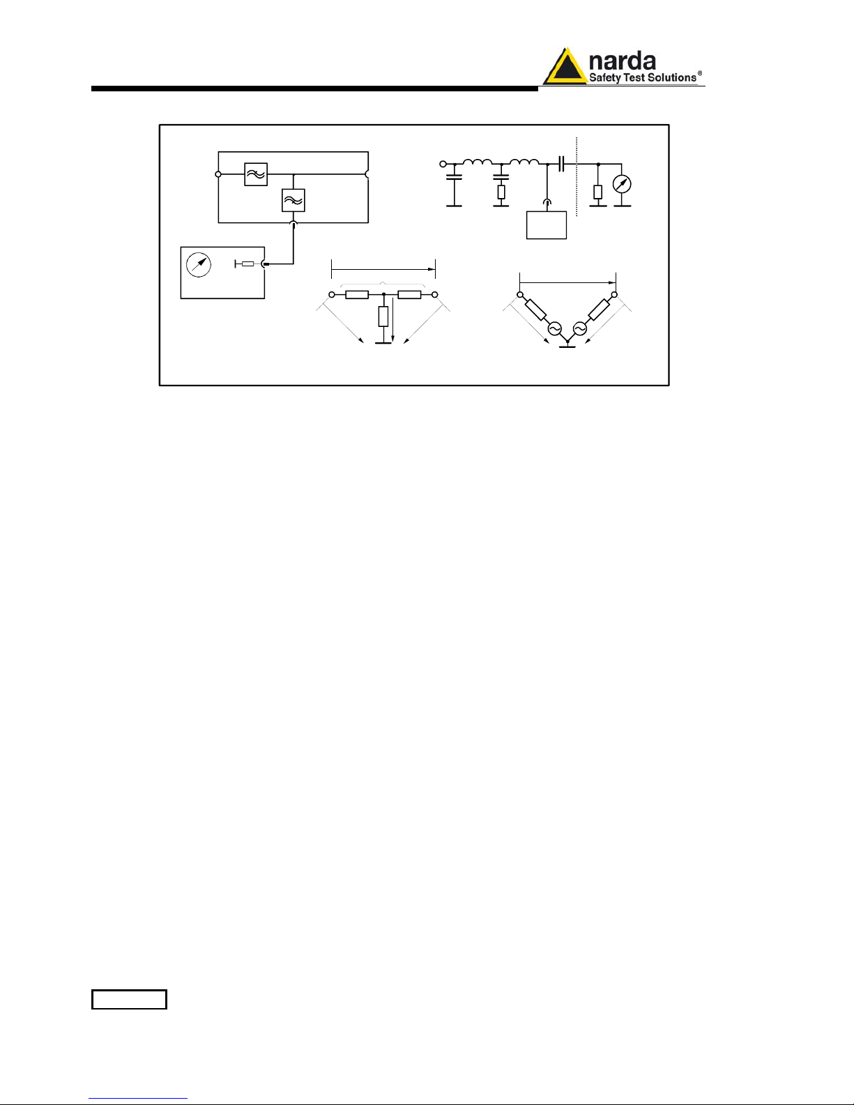
7-2 Applications
Fig. 7-1 AMN Principle: a) Δ-type or T-type LISN ; b) V-type LISN
7.1.2.1 AMN
AMNs are usually classified depending their configuration: V-type
Networks, Δ-type Networks, T-type Networks.
• The V-type Network is used for measuring the unsymmetrical RFI
voltage on AC and DC supply line. Standard impedances specified by
CISPR and other international standards are 50Ω // 50 μH+5Ω and 50Ω
// 5 μH+1Ω.
• The Δ-type Network is used for measuring the symmetrical RFI voltage
on balanced telecommunication lines. It is generally designed to permit
switchover between symmetrical and asymmetrical RFI measurements.
Its use is limited; Standards usually specify the T-type Network instead.
The most common impedance for Δ-type Network is 150Ω.
• The T-type Network is used for measuring the asymmetrical RFI
voltage on balanced (electrically symmetrical) audio frequency, control
and data lines. Standard impedance is 150Ω as well.
An Artificial Mains Network shall be designed in order to:
1. terminate each line (power, signal, etc.) of the EUT (Equipment Under
Test) with a standardized impedance;
2. permit the feeding of the EUT with the proper supply voltage and
current or with the signal and data required for operations;
3. isolate the side of the test circuit where EMI voltages are measured
against interference coming from mains network or from the auxiliary
equipment supplying the EUT with the required data;
4. provide a suitable test point – to be connected to the test receiver - to
pick up the RFI voltages from the conductor under test;
5. ensure that the impedance of the source (power, signal) is not varied in
a significant way, otherwise EUT response to the interference may
change.
lowpass
filter
highpass
filter
mains
DUT
test
receiver
RF load to
inter fer ence
DUT
50
Ω
8μF
5
Ω
50μH0.25μF
test
receiver
mains
V-LISN
V
sym
V
asym
Z
asym
Z
sym
V
unsym
V
unsym
2μF
250
μ
H
V
unsym
V
unsym
V
sym
L
1
L
2
L
1
L
2
L
1
a) b)
V-LISN
(only one
line is shown)
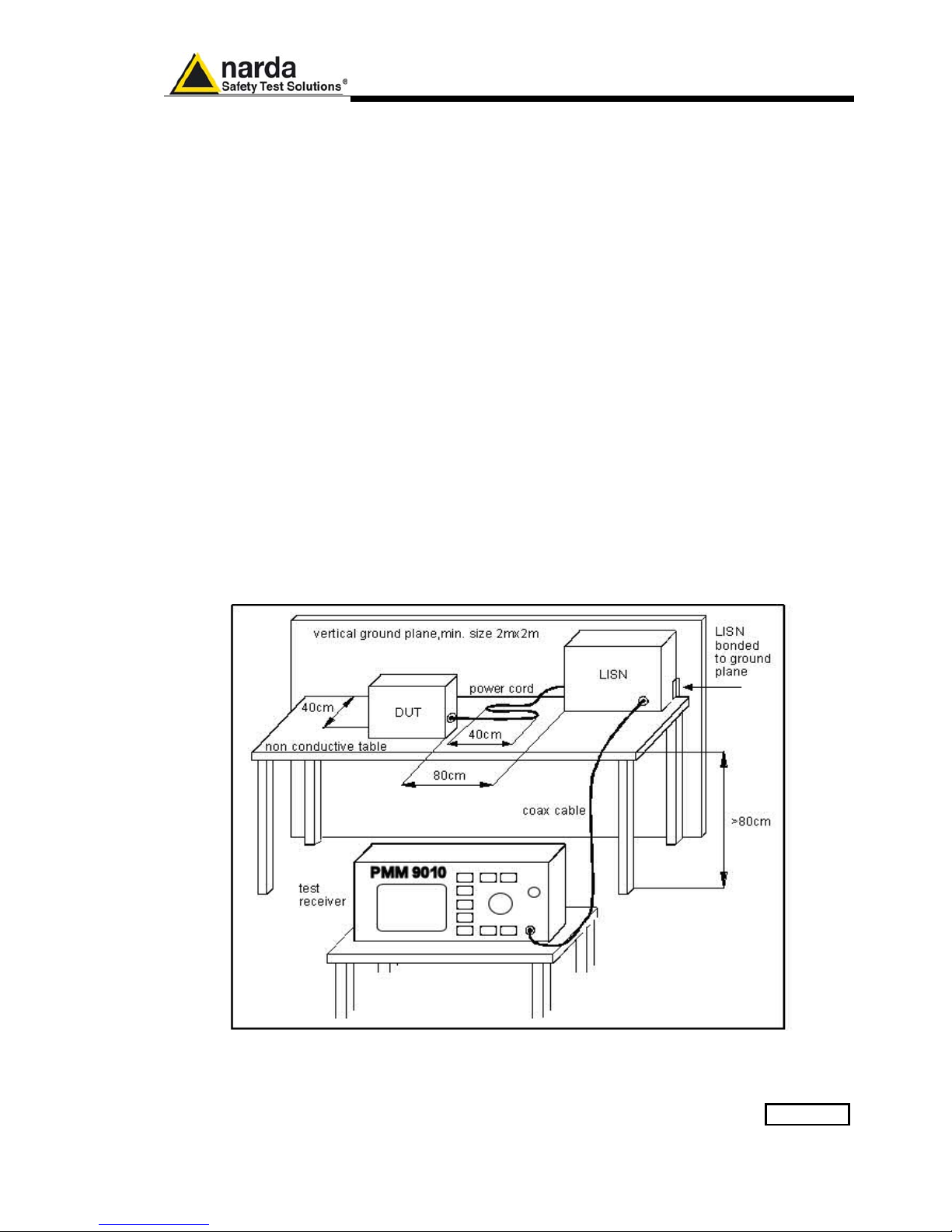
Applications 7-3
7.1.2.2 Current Probe
Current Probes may be Clamp-on Probes or Fixed-ring Probes.
Current Probes are used to measure differential or common mode RFI
currents. In some cases it may be important to make a distinction between
the two kinds of current flowing in a system.
RFI current measurements with Current Probes may be required, for
example, when measuring EMI from shielded lines or from complex wiring
systems, when finding interference sources among other sources in a
system, when performing compliance to some Standards, etc.
7.1.2.3 Voltage Probe
Voltage Probes include Active Probes and Passive Probes.
Active Probe has a very high input impedance Zin > 100 KΩ // < 10 pF.
Passive Probe has a standard impedance Zin = 1,5 KΩ // < 10 pF.
Voltage Probe is used for measuring the unsymmetrical RFI voltage when
it is not possible to carry out measurement by interconnecting an Artificial
V-type Network. Such situation may occur, for example, when measuring
on lines on which only small loads are permissible (control and signal
lines), when measuring on a EUT (Equipment Under Test) which would
not operate correctly using V-type LISN or a DUT (Device Under Test)
requiring very high power supply current for which no V-type LISN is
available.
For diagnostic or design purposes on high impedance circuits, Voltage
Probe may be used to determine, for example, noisy components or
conductors that cause interference on CMOS PC boards.
Some Regulations give statements when Voltage Probe are to be used
and specify relevant setup and RFI voltage limits.
Fig. 7-2 Example of Test Setup for RFI Voltage Measurement

7-4 Applications
7.1.3 Test Setup
Fig. 7-2. shows an example of test setup for RFI voltage measurement.
The DUT is placed 0,4 m from an horizontal or vertical earthed conducting
surface of at least 2 m x 2 m in size.
A table top DUT is placed 0,8 m from the LISN and at least 0,8 m from any
other earthed conducting surface. If the measurements are made in a
shielded room, the DUT shall be placed 0,4 m from one of the walls of the
room.
The LISN shall be bonded to the reference conducting surface.
A Floor standing DUT is placed 0,1 m above an horizontal earthed
conducting surface of at least 2 m x 2 m in size. This size shall be
exceeding by at least 0,5 m the projection of the DUT on the conducting
surface. The power cable should be 1m long; longer cable should be
centrally bundled for at least 40 cm.
DUTs without a PE (Protective Earth) conductor and manually operated
DUTs shall be measured in conjunction with an auxiliary screen or an
“Artificial Hand”, as duly specified in the relevant standards.
All the details and information on the test setup are written on the latest
version of the applicable Standard.
7.1.4 Guidance on a
preliminary
Measuring
Procedure
A step-by-step example of a conducted test manually performed is the
following:
1. Switch ON the PMM 9010 and enter in Sweep Mode pressing the
relevant button;
2. Select Display and then 120dB; Reference Level should be between
110 and 135 dBμV; press Esc;
3. Touch the Measure key, then Freq and A+B Band;
4. Then Level, Input and set the Minimum Attenuation to 10 dB and the
Attenuation is automatic; press Esc;
5. Select Misc, Presel and Pulse Limiter to enable the preselction and
the protection of the input from voltage spikes; press Esc;
6. Enter in the Detector menu and select Peak; press Esc two times;
7. Connect a LISN or any other suitable transducer to the RF input,
selecting the proper phase/line whenever applicable;
8. With the EUT switched OFF touch Exec Sweep and wait until the first
scan has been finished;
9. Carry out an overview of the whole spectrum and check the by
executing a pre-measurement with peak detector that the ambient RF
disturbances are at least 20 dB below the desired emission levels;
10. If the ambient noises are low enough continue to the next step,
otherwise take all the necessary steps to reduce the ambient
disturbances (e.g. go to a shielded room, etc.);
11. Switch ON the EUT and then Measure, Exec Sweep again and wait
until the scan has been finished;
12. Enter in the Display menu and adjust the Dynamic Range and the
Reference Level to the most convenient visualization;
13. If the results are satisfactory select Marker, Peak and then either
Analyzer or Tune to enter respectively in Spectrum Mode or in Manual
Mode and deeply investigate the highest signals;
14. If the results of the scan need to be refined, select a Limit, if
appropriate, and then Measure, Level and Smart Detector (if a limit
has been loaded);
15. In the Smart Detector menu check the best combination among those
listed; enter a Margin, if needed; press Esc;
16. Exec Sweep again and repeat from step #12.

Applications 7-5
7.1.5 Remarks and Hints
for Measuring
To avoid errors caused by ambient interference, measurements should be
carried out inside a properly shielded room. Different sites, like basements
or other rooms with low ambient interferences, are often sufficient for a
preliminary evaluation.
Conducted measurements do not strictly require any anechoic
environment, while radiated tests may need it if so specified by the relevant
standard.
Using the PMM 9010 SW Utility running on an external PC it is possible to
make automatic measurements and to automatically select LISNs lines
(with a PMM LISN), etc.

7-6 Applications
This page has been left blank intentionally

Updating Firmware 8-1
8 – Updating firmware and
Activation code Utility
8.1 Introduction
The PMM 9010 features a simple and user-friendly method for updating its
internal firmware through a Personal Computer (PC).
The “WrDongle” embedded in the FW Upgrade Tool is used for the
Options activation procedure.
This section provides all the information required for easy updating.
8.2 System requirements
The minimum requirements to allow the software to operate properly are
the following:
• 486 Processor or Pentium
• 16 Mb of RAM
• at least 10 Mb of free space on hard disk
• 1 free Serial Port (RS-232), or, alternatively, a USB/RS-232 Adapter
with related driver
• Windows Operating System™ 95/98/2000/XP/Vista/Win7
The User must have administrator privileges to install the software in
Windows 7; right click on the program .exe file and click on “Run as
administrator” to temporarily run the program or application as an
administrator until close it (Windows 7 also allows to mark an
application so that it always runs with administrator rights).
8.3 Preparing the
Hardware
Turn off the PMM 9010 and connect the RS-232 cable supplied with the
apparatus directly or through a USB/RS-232 Adapter separately purchased
(once related driver has been properly installed), to the 9 pin socket
situated on the back panel of PMM 9010 on one side and to a free RS232
port (or USB in case of Adapter’s use) on the PC side.
The first free RS-232 port will be automatically detected by the Firmware
Update Program during installation. In case of troubles please check port
assignments on the PC through the Control Panel utility.
8.4 Software
Installation
The Update Firmware and 9010 WrDongle executable programs are
provided together with the 9010 Software Utility stored on Software Media
and included in PMM 9010 Receiver package; anyway it’s always possible
to check for newer releases and download them from official NARDA Italy
Web Site Support page.
Once the 9010SeriesUp Setup has been installed in the PC, another item
is created in the Programs list at Start Menu, which is “PMM Emission
Suite”, from where the “9010SeriesUp” and “WrDongle” programs can be
easily run.
Document 9010EN-81037-2.57 - © NARDA 2018
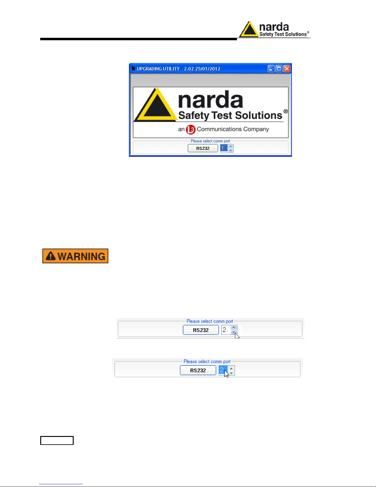
8-2 Updating Firmware
Click on “9010SeriesUp” (9010SeriesUp.exe) once for running the update
program, so getting the following window:
Two firmware components can be updated by this application: Firmware,
which is the receiver internal program, and FPGA, to update the internal
programmable logic.
The 9010FW.bin file required for Firmware updating and the PPI_ramp.bin
file for FPGA are automatically stored in the same directory of the
9010SeriesUp.exe, otherwise just copy them there before performing the
upgrade.
Be sure batteries of PMM 9010 and connected Laptop (PC) are fully
charged before performing the FW Upgrade, otherwise the upgrade
progress could not terminate properly.
Alternatively, be sure to have both PMM 9010 and Laptop (PC) powered
through their respective AC/DC power adapters.
Anyway, even in case of failure, the internal BIOS will never be
corrupted and you’ll just need to repeat the procedure once more (this
is a unique feature!).
Should FW Upgrade procedure stop before reaching the 100%
completion that will have not to be considered a trouble but simply an
intermediate step: in this case please switch OFF and ON the receiver
and repeat the FW Upgrade procedure once more until the end.
Always cycle power OFF and ON again after every FW Upgrade.
Choose the COM port pressing the Up or the Down arrows.
Move the cursor to the COM port number and select the left mouse button to
highlight the box.
Press RS232 button or Enter key to set the com port.
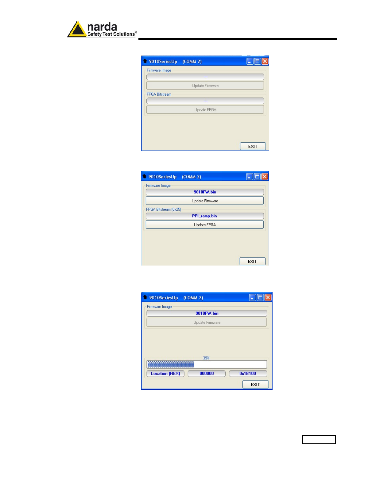
Updating Firmware 8-3
The program will display the following window:
8.5 To transfer data
To start the process simply switch PMM 9010 on, select Update Firmware
or Update FPGA button, and wait until the automatic transfer is completed.
During the firmware storing procedure, a blue bar will progress from left to
right in the window of the PC, showing percentage of downloading time by
time until 100%.

8-4 Updating Firmware
In the meanwhile on the 9010 display the BIOS page appears, showing
again the updating status.
When FW download finishes, following message appears to show that
everything was properly completed:
In case of failure, an error message is showed instead.
After Firmware Update is successfully completed, switch OFF and then ON
again the PMM 9010, looking at screen, and then perform Auto-calibration.
Now at the top of the display a different FW Release Number and Date is
showed after “9010-BIOS-…”, as per the following:
In case the release should not comply with what expected, just check
about the FW file used during installation or get in contact with the nearest
NARDA Local Distributor.
It is now possible to disconnect the cable connected to the PC, with the
PMM 9010 receiver either switched On or Off.
To obtain up-to-date Firmware or PC Utility for PMM 9010, the user
can contact his NARDA distributor or download it directly from
Support area of EMC Product Range on the following Web Site:
www.narda-sts.it.
After having upgraded the internal firmware of the unit it is suggested
to perform the Auto-calibration procedure as described in chapter
3.3.

Updating Firmware 8-5
8.6 9010 WrDongle
utility
The WrDongle utility allows to enable the function ordered such Options
using the 40 Digit Activation Code received from NARDA Italy.
Turn on the PMM 9010 and connect it to a free USB or RS232 port of the
PC.
Browse for All Programs from the Start Menu and reach the “WrDongle”
executable link:
Main window displayed after the program WrDongle has been run:
Select USB or RS232 communication port.
In case of RS232 communication, choose the COM port pressing the Up or
the Down arrows.
Move the cursor to the COM port number and select the left mouse button to
highlight the box.
Press RS232 button to set the com port.

8-6 Updating Firmware
The program will display the following window:
Copy and paste the 40 Digit Activation Code to the “Dongle Code” input
field and press the button below related to the specific Option:
In case of failure, an error message is showed instead.
Always cycle OFF and ON the receiver to properly initialize the function.
For further information on activation procedure refer to the “Click
Mode Operating Instructions”, “RMS-AVG and C-AVG Detectors”, and
“Additional RBW Filters” chapter.
With the “Write 03P to 30P Dongle” button the 9010/03P can be
upgraded to 9010/30P version for use up to 3 GHz; It is a payment
special function implemented in the receiver. Please contact your local
Narda distributor for details.

General Information 9-1
9 – PMM 9010/03P EMI CISPR Receiver
10 Hz ÷ 30 MHz Full Compliance
> 30 MHz Compliance (PRF ≥ 10Hz)
PMM 9010/30P EMI CISPR Receiver
10 Hz ÷ 30 MHz Full Compliance
30 MHz ÷ 3 GHz Pre Compliance
PMM 9010/60P EMI CISPR Receiver
10 Hz ÷ 30 MHz Full Compliance
30 MHz ÷ 6 GHz Pre Compliance
General Information
Document 9010EN-81037-2.57 - © NARDA 2018

9-2 General Information
9.1 Documentation
Enclosed with this manual are:
• a service questionnaire to send back to NARDA in case an equipment
service is needed
• an accessories checklist to verify all accessories enclosed in the
packaging.
9.2 Operating
Manual Changes
Instruments manufactured after the printing of this manual may have a
serial number prefix not listed on the title page; this indicates that
instruments with different Serial Number prefix may be different from those
documented in this manual.
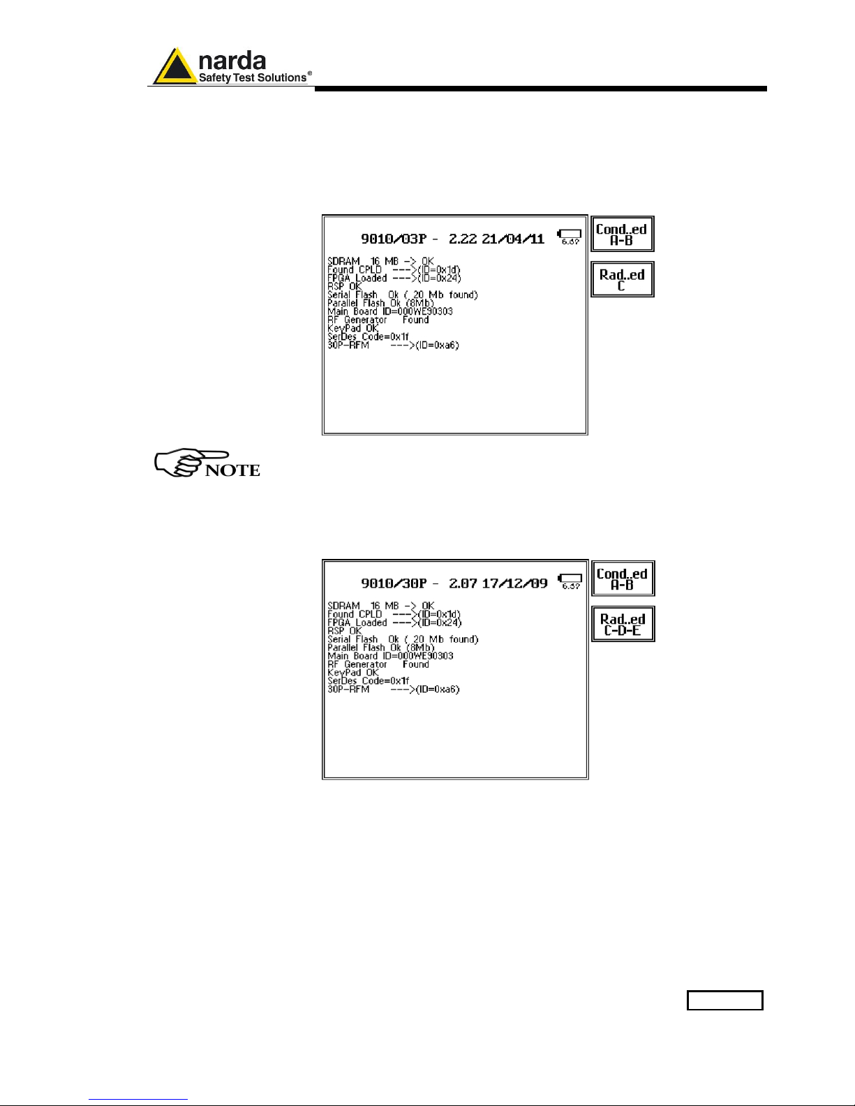
General Information 9-3
9.3 Introduction to
PMM 9010/03P/30P/60P
PMM 9010/03P/30P/60P is an EMI receiver to measure conducted and
radiated interferences from 10 Hz to 300 MHz (9010/03P), from 10 Hz to 3
GHz (9010/30P) and from 10 Hz to 6 GHz (9010/60P).
The 9010/03P is Full Compliance up to 30 MHz (A and B band) and
Compliance 30 MHz up to 300 MHz (C band, PRF ≥ 10Hz).
The 9010/03P can be upgraded to 9010/30P version for use up to 3
GHz; It is a payment special function implemented in the receiver.
Please contact your local Narda distributor for details.
The 9010/30P is Full Compliance up to 30 MHz (A and B band) and Pre-
Compliance 30 MHz up to 3 GHz (CDE bands).

9-4 General Information
The 9010/60P is Full Compliance up to 30 MHz (A and B band) and Pre-
Compliance 30 MHz up to 6 GHz (CDE bands).
For what is concerning the use in full compliance A and B bands refer
to the PMM 9010.
Refer to the PMM 9030/9060/9180 chapter for the main functions are
included in Radiated emission measurements.
All measurements performed by the PMM 9010/03P/30P/60P are
according to the most accepted standards like: IEC, CISPR, EN
(EuroNorm), FCC, VDE, ….
Thanks to its built-in tracking generator up to 30MHz the PMM
9010/03P/30P/60P is also suitable for designing, characterizing and testing
RF filters, transducers and other components.
The PMM 9010/03P/30P/60P has been designed adopting an innovative
philosophy made possible only in the recent years by the availability of
superior technology components. This equipment is fully digital but the
input preselector and attenuator – and, of course, the output stage of the
internal reference tracking generator - and therefore combines into a pure
EMI Receiver and Signal Analyzer the precision and accuracy of a numeric
approach, with flexibility and user friendly approach typical of a modern
instrument.
9.4 Instrument Items
PMM 9010/03P/30P/60P includes the following items:
• PMM EMI Receiver;
• External power supply/battery charger;
• Flexible black cover/accessories holding;
• BNC-BNC coaxial cable 2m length;
• N male to BNC fem. Adapter
• RS232 cable, 2m;
• USB cable, 2m;
• Operating manual;
• PMM 9010 Utility Software on Software Media;
• Certificate of Compliance;
• Return for Repair Form.
9.5 Optional
accessories
• BP-02 Li-ion battery pack;
• Same optional accessories of 9010 unit (See par. 1.5)
9.6 Other accessories
• Same other accessories of 9010 unit (See par. 1.6)

General Information 9-5
9.7 PMM 9010/03P
Main Specifications
Table 9-1 lists the PMM 9010/03P performance specifications.
The following conditions apply to all specifications:
• The ambient temperature shall be 0°C to 40°C
For what is concerning the specifications of the A and B bands
section refer to the specification of the 9010 in the chapter 1.
TABLE 9-1 Main Specifications for C bands
Frequency range
Resolution
Frequency accuracy
30 MHz to 300 MHz
100 Hz
< 2 ppm
RF input
VSWR
10 dB RF att.
0 dB RF att.
Attenuator
Z
in
50 Ω, N fem.
< 1.2
< 1.2
0 dB to 50 dB (2dB steps)
Max input level
(without equipment damage)
Sinewave AC voltage
Pulse spectral density
137 dBuV (1 W)*
97 dBµV/MHz
PRF (CISPR 16-1-1)
≥ 10Hz
IF bandwidth
Standard 6 dB
CISPR 16-1-1 bandwidth (6 dB)
MIL-STD-461 (option)
3, 10, 30, 100, 300 kHz, 1 MHz
120 kHz
100 kHz, 1 MHz
Noise level
30 to 300 MHz < 8 dBµV (QP)
(120 kHz RBW) < 4 dBµV (AV)
Spurious response
< 15 dBµV
Measurement accuracy
S/N > 20 dB
± 1,0 dB
Operating temperature
Power supply
0° to 40°C
10 - 15 Volt DC, 2,5A; Optional Li-Ion interchangeable
battery (8 h operations, typical)
Dimensions
235 x 105 x 335 mm
Weight
4.1 kg
(*) with MIN ATT ≥ 10 dB

9-6 General Information
9.8 PMM 9010/03P
Front Panel
Fig. 9-1 Front Panel
Legend from left to right:
- USB USB 2.0 connection port (future implementation only)
- PW Power led
Indicates the power status
-
Earphone connector
To listen to the demodulated signals
- DISPLAY Main display
To graphically show the instrument status
- User keys 5 command keys
To select the various available functions
- Controls Rotary Knob, Left and Right (decrease / increase) Arrow Keys; Esc; Enter/Switch Key
The Rotary Knob and the Arrows Keys can be used to increase and decrease the
setting values; the Esc key allows to return to the previous status/display;
the Enter/switch key is used to confirm a set value and to switch On and Off
the equipment
- Input connectors
Input from 10 Hz ÷ 30 MHz (BNC connector)
Input > 30 MHz (N connector)
- “RF Input 50Ω 10 Hz ÷ 30 MHz” Led
Indicates when the Receiver Input is active
- “RF Input 50Ω > 30 MHz” led
Indicates when the Receiver Input is active

General Information 9-7
9.9 PMM 9010/03P
Rear Panel
Fig. 9-2 Rear Panel
Legend from left to right:
- RS232 9 pin, DB9 connector
- USER PORT User I/O Port
- USB Fully functional USB 2.0 Port
- LINK1/LINK2 Optical link connectors for PMM equipments (Link 2 for future implementation)
- Power Supply Power Supply Inputs for use to power the apparatus and simultaneously charge
its battery (PS1) and to simply charge the battery when it’s out of the receiver
(PS2).
- Output connector Tracking Generator Output
- Fan Cooling Fan controlled by firmware
- Replaceable Li-Ion Battery (Fig. 9-3) with main Battery Charger connector
- Earth ground connector
- Product Label and Serial Number
Fig. 9-3 BP-02 Replaceable Battery
To upgrade the firmware, install and use the PMM 9010/03P refer to
PMM 9010 section.
PS1
PS2

9-8 General Information
9.10 PMM 9010/30P
Main Specifications
Table 9-2 lists the PMM 9010/30P performance specifications.
The following conditions apply to all specifications:
• The ambient temperature shall be 0°C to 40°C
For what is concerning the specifications of the full compliance A
and B bands section refer to the specification of the 9010 in the
chapter 1.
TABLE 9-2 Main Specifications for CDE bands
Frequency range
Resolution
Frequency accuracy
30 MHz to 3 GHz
100 Hz
< 2 ppm
RF input
VSWR
10 dB RF att.
0 dB RF att.
Attenuator
Z
in
50 Ω, N fem.
< 1.2, <2.0 over 1 GHz
< 1.2, <2.0 over 1 GHz
0 dB to 50 dB (2dB steps)
Max input level
(without equipment damage)
Sinewave AC voltage
Pulse spectral density
PRF (CISPR 16-1-1)
137 dBµV (1 W)*
97 dBµV/MHz
≥ 10Hz
IF bandwidth
Standard 6 dB
CISPR 16-1-1 bandwidth (6 dB)
MIL-STD-461 (option)
3, 10, 30, 100, 300 kHz, 1 MHz
120 kHz
100 kHz, 1 MHz
Noise level
30 MHz to 3 GHz < 8 dBµV (QP)
(120 kHz RBW) < 4 dBµV (AV)
Spurious response
< 15 dBµV
Measurement accuracy
(S/N > 20 dB)
30 MHz to 1 GHz ± 1,0 dB
1 GHz to 3 GHz ± 1,5 dB
Operating temperature
Power supply
0° to 40°C
10 - 15 Volt DC, 2,5A; Optional Li-Ion interchangeable
battery (8 h operations, typical)
Dimensions
235 x 105 x 335 mm
Weight
4.1 kg
(*) with MIN ATT ≥ 10 dB

General Information 9-9
9.11 PMM 9010/30P
Front Panel
Fig. 9-4 Front Panel
Legend from left to right:
- USB USB 2.0 connection port (future implementation only)
- PW Power led
Indicates the power status
-
Earphone connector
To listen to the demodulated signals
- DISPLAY Main display
To graphically show the instrument status
- User keys 5 command keys
To select the various available functions
- Controls Rotary Knob, Left and Right (decrease / increase) Arrow Keys; Esc; Enter/Switch Key
The Rotary Knob and the Arrows Keys can be used to increase and decrease the
setting values; the Esc key allows to return to the previous status/display;
the Enter/switch key is used to confirm a set value and to switch On and Off
the equipment
- Input connectors
Input from 10 Hz ÷ 30 MHz (BNC connector)
Input from 30 MHz ÷ 3 GHz (N connector)
- “RF Input 50Ω 10 Hz ÷ 30 MHz” Led
Indicates when the Receiver Input is active
- “RF Input 50Ω 30 MHz ÷ 3 GHz” led
Indicates when the Receiver Input is active

9-10 General Information
9.12 PMM 9010/30P
Rear Panel
Fig. 9-5 Rear Panel
Legend from left to right:
- RS232 9 pin, DB9 connector
- USER PORT User I/O Port
- USB Fully functional USB 2.0 Port
- LINK1/LINK2 Optical link connectors for PMM equipments (Link 2 for future implementation)
- Power Supply Power Supply Inputs for use to power the apparatus and simultaneously charge
its battery (PS1) and to simply charge the battery when it’s out of the receiver
(PS2).
- Output connector Tracking Generator Output
- Fan Cooling Fan controlled by firmware
- Replaceable Li-Ion Battery (Fig. 9-6) with main Battery Charger connector
- Earth ground connector
- Product Label and Serial Number
Fig. 9-6 BP-02 Replaceable Battery
To upgrade the firmware, install and use the PMM 9010/30P refer to
PMM 9010 section.
PS1
PS2

General Information 9-11
9.13 PMM 9010/60P
Main Specifications
Table 9-3 lists the PMM 9010/60P performance specifications.
The following conditions apply to all specifications:
• The ambient temperature shall be 0°C to 40°C
For what is concerning the specifications of the full compliance A
and B bands section refer to the specification of the 9010 in the
chapter 1.
TABLE 9-3 Main Specifications for CDE bands
Frequency range
Resolution
Frequency accuracy
30 MHz to 6 GHz
100 Hz
< 2 ppm
RF input
VSWR
10 dB RF att.
0 dB RF att.
Attenuator
Z
in
50 Ω, N fem.
< 1.2, <2.0 over 1 GHz
< 2.0, <3.0 over 3 GHz
0 dB to 55 dB (5dB steps)
Max input level
(without equipment damage)
Sinewave AC voltage
Pulse spectral density
PRF (CISPR 16-1-1)
137 dBµV (1 W)*
97 dBµV/MHz
≥ 10Hz
IF bandwidth
Standard 6 dB
CISPR 16-1-1 bandwidth (6 dB)
MIL-STD-461 (option)
3, 10, 30, 100, 300 kHz, 1 MHz
120 kHz
100 kHz, 1 MHz
Noise level
30 to 300 MHz < 10 dBuV (QP)
(120 kHz BW) < 7 dBuV (AV)
300 to 3000 MHz < 13 dBuV (QP)
(120 kHz BW) < 7 dBuV (AV)
3000 to 6000 MHz < 15 dBuV (QP)
(120 kHz BW) < 10 dBuV (AV)
Spurious response
< 10 dBµV, < 15 dBµV over 2 GHz
Measurement accuracy
(S/N > 20 dB)
30 MHz to 1 GHz ± 1,0 dB
1 GHz to 3 GHz ± 1,5 dB
3 GHz to 6 GHz ± 2,0 dB
Operating temperature
Power supply
0° to 40°C
10 - 15 Volt DC, 2,5A; Optional Li-Ion interchangeable
battery (8 h operations, typical)
Dimensions
235 x 105 x 335 mm
Weight
4.1 kg
(*) with MIN ATT ≥ 10 dB

9-12 General Information
9.14 PMM 9010/60P
Front Panel
Fig. 9-7 Front Panel
Legend from left to right:
- USB USB 2.0 connection port (future implementation only)
- PW Power led
Indicates the power status
-
Earphone connector
To listen to the demodulated signals
- DISPLAY Main display
To graphically show the instrument status
- User keys 5 command keys
To select the various available functions
- Controls Rotary Knob, Left and Right (decrease / increase) Arrow Keys; Esc; Enter/Switch Key
The Rotary Knob and the Arrows Keys can be used to increase and decrease the
setting values; the Esc key allows to return to the previous status/display;
the Enter/switch key is used to confirm a set value and to switch On and Off
the equipment
- Input connectors
Input from 10 Hz ÷ 30 MHz (BNC connector)
Input from 30 MHz ÷ 6 GHz (N connector)
- “RF Input 50Ω 10 Hz ÷ 30 MHz” Led
Indicates when the Receiver Input is active
- “RF Input 50Ω 30 MHz ÷ 6 GHz” led
Indicates when the Receiver Input is active
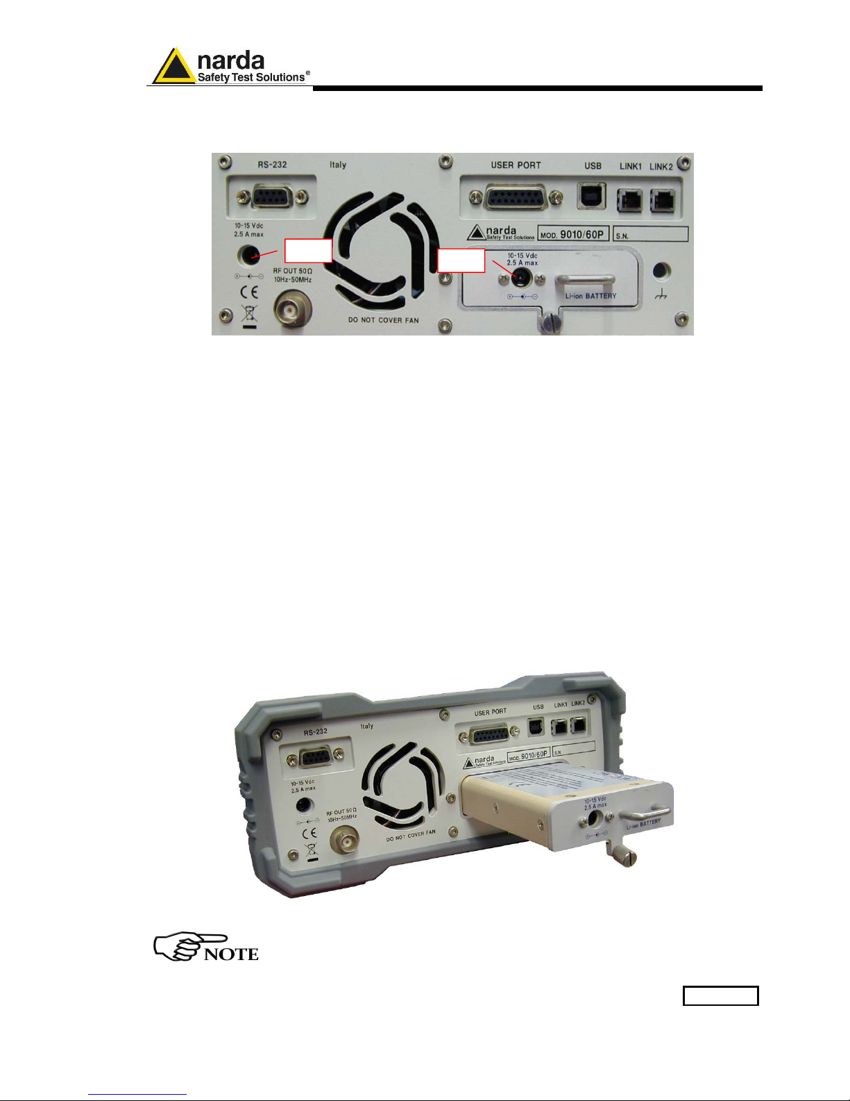
General Information 9-13
9.15 PMM 9010/60P
Rear Panel
Fig. 9-8 Rear Panel
Legend from left to right:
- RS232 9 pin, DB9 connector
- USER PORT User I/O Port
- USB Fully functional USB 2.0 Port
- LINK1/LINK2 Optical link connectors for PMM equipments (Link 2 for future implementation)
- Power Supply Power Supply Inputs for use to power the apparatus and simultaneously charge
its battery (PS1) and to simply charge the battery when it’s out of the receiver
(PS2).
- Output connector Tracking Generator Output
- Fan Cooling Fan controlled by firmware
- Replaceable Li-Ion Battery (Fig. 9-6) with main Battery Charger connector
- Earth ground connector
- Product Label and Serial Number
Fig. 9-9 BP-02 Replaceable Battery
To upgrade the firmware, install and use the PMM 9010/60P refer to
PMM 9010 section.
PS1
PS2

9-14 General Information
This page has been left blank intentionally

Click Mode Operating Instructions 10-1
10 - Click Mode Operating Instructions
(Option)
10.1 Introduction
The CLICK mode allows the User to make in a fast, easy and fully
automatic way a difficult test like the Discontinuous Disturbances
measurement, as defined by current CISPR standards.
10.2 Click Mode
Activation
Procedure
To enable the Click mode use the 9010 Set code Utility
For further information on software installation, refer to the “Updating
firmware and Activation code Utility” chapter.
Click on “9010 Set code Utility” (WrDongle.EXE) once for running the
Set code program, so getting the following window:
Choose the proper COM port from the drop-down menu and click the
RS232 button.
Document 9010EN-81037-2.57 - © NARDA 2018
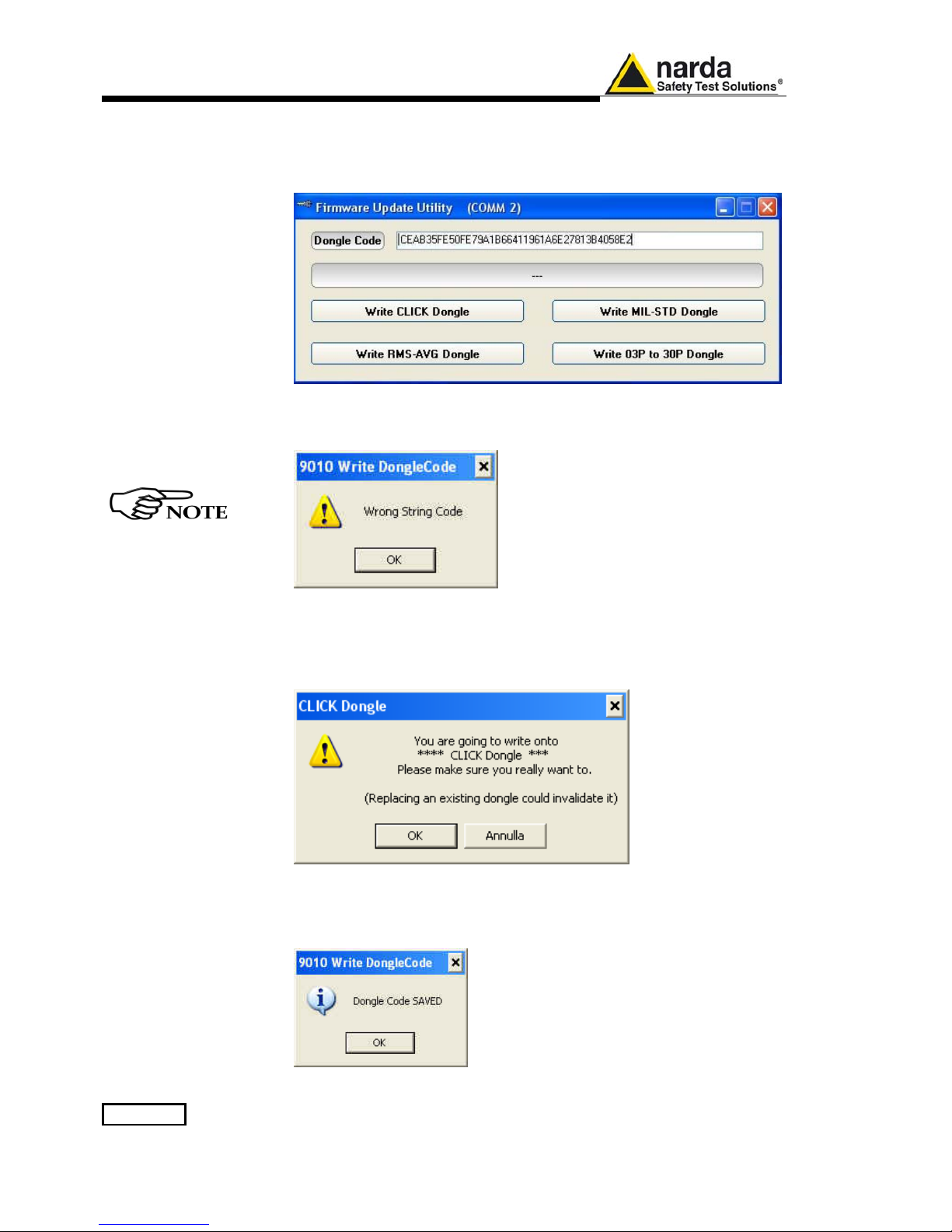
10-2 Click Mode Operating Instructions
Copy the 40 Digit Serial Code in the Dongle Code Window and select the
Write Click Dongle button.
This message appears when the Dongle code is not valid
When everything works correctly, the following message will be shown.
Then press OK to confirm.
The software will inform that the Dongle Code has been successfully
stored. Press Ok to close the program.
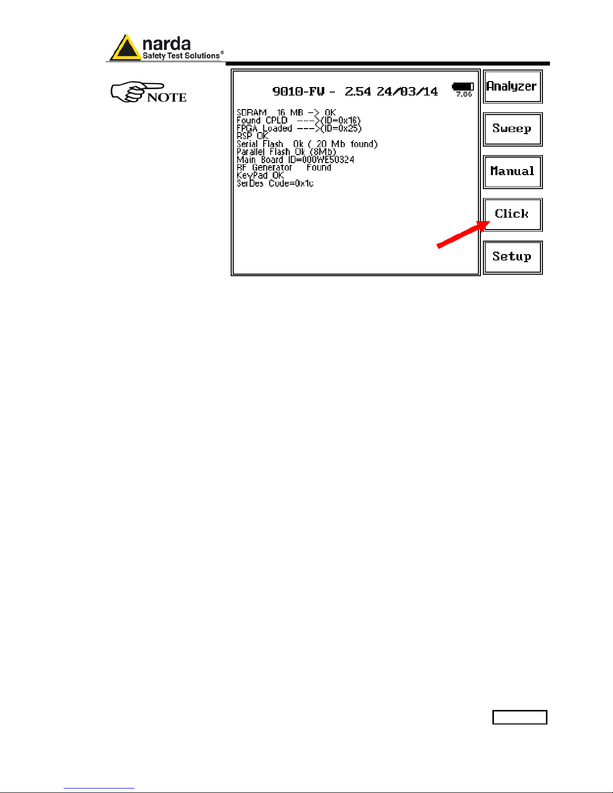
Click Mode Operating Instructions 10-3
Click activation confirm
When the Click option has been successfully activated, the 4
th
menu button
appears as indicated in the picture above.

10-4 Click Mode Operating Instructions
10.3 Enter the Click
Mode
To enter Click Mode, press the corresponding key in the main menu, and
immediately the first window opens as following:
With PMM 9010/03P /30P /60P press the Cond..ed A-B key in the initial
menu to enter the main menu where the Click Mode button appears.
Fig. 10-1 Click
This is the IDLE function, which allows a preliminary, free running
evaluation, at the selected frequency and level.
The Click mode function has four commands:
• Start
• Clear: cancel and reset all data to start an idle test;
• Report
• SETUP
Always use Esc button to return to the previous view/condition.
To increase test productivity the PMM 9010, PMM 9010/03P/30P/60P or
PMM 9010F has some very unique features: it allows skipping as many as
2 steps, as it may predict how many clicks would overcome the Lq limit and
may also advice the User if the next step would fail.
Moreover, it makes a true Qpeak measure and not a mere threshold
comparison, as only a fully digital receiver can detect whether a Qpeak
level came from an unsaturated signal or not; an analogue analyzer only
has the final weighted Qpeak.

Click Mode Operating Instructions 10-5
10.4 Introduction
to the discontinuous
disturbance (click)
measurement
Mechanical or electronic switching procedures - e.g. those due to
thermostats or program controls – may unintentionally generate broadband
discontinuous disturbances with a repetition rate lower than 1 Hz.
Indeed, CISPR 16-2-1 and CISPR 14-1 define a discontinuous
disturbance, also called “click”, as a disturbance the amplitude of which
exceeds the quasi-peak limit of continuous disturbance, the duration of
which is not longer than 200 ms and which is separated from a subsequent
disturbance by at least 200 ms. The durations are determined from the
signal which exceeds the IF reference level of the measuring receiver.
A click may also contain a number of impulses; in which case the relevant
time is that from the beginning of the first to the end of the last impulse.
The test procedures and the test setup for click measurement are indicated
in CISPR 16-2-1 and in CISPR 14-1 standards.
It basically consists in the measurement of the number of clicks exceeding
a certain level determined as function of the click number and duration.
The PMM 9010 has a better then 500µs time resolution, as requested by
the standard.
Moreover, several “exceptions” shall be dealt with by the click analyzer in
order to make the test as per the standard.
To better understand the click measurement process – automatically made
by PMM 9010 - it could be useful also to know few more definitions:
• switching operation: one opening or closing of a switch or contact;
• minimum observation time T: the minimum time necessary when
counting clicks (or switching operations) to provide firm evidence
for the statistical interpretation of the number of click (or switching
operations) per time unit;
• click rate N: number of clicks or switching operations within one
minute (this figure is being used to determine the click limit);
• Click limit Lq: the relevant limit L for continuous disturbance for the
measurement with the quasi-peak detector, increased by a certain
value (offset) determined from the click rate N. The click limit
applies to the disturbance assessed according to the upper
quartile method;
• Upper quartile method: a quarter of the number of the clicks
registered during the observation time T is allowed to exceed the
click limit Lq. In the case of switching operations a quarter of the
number of switching operations registered during the observation
time T is allowed to produce clicks exceeding the click limit Lq.
• short click 1: a disturbance not longer than 10 ms;
• short click 2 (E3): a disturbance between 10 ms and 20 ms;
• click: a disturbance longer than 10 ms and not longer than 200 ms;
• other than click: a discontinuous disturbance longer than 200 ms.
With reference to the mentioned standards, a schematic process flow of
the measurement is the following:
● Determination of the click rate N
● Pass/fail decision if instantaneous switching and if N>=30
● Check conformity to definitions
● Apply Exceptions (whenever applicable)
● Calculate Limit Quartile
● Measurement using Upper Quartile Method
● Pass/fail using Upper Quartile criterion
● Repeat for next frequency
As PMM 9010 manages all these steps in a completely automatic way, a
detailed step by step description is here given before to describe each
command and function.

10-6 Click Mode Operating Instructions
10.4.1 Determination of
the click rate
The first step of the measuring process is to determine the click rate N in
the minimum observation time. This is done measuring the time needed to
count up to 40 clicks or 40 switching operations; the maximum time
allowed is anyway 2 hours (120 minutes), unless the cycle is determined
by a program, which needs additional time to be terminated.
Therefore, if the equipment has a cycle and in this cycle less than 40 clicks
appear, then the cycle shall be repeated until 40 clicks are counted or until
the observation time is 2 hours.
If the equipment has a cycle and in this cycle more than 40 clicks appear,
the observation time is anyway determined by the cycle.
When the minimum observation time has been defined, it is possible to
calculate the click rate N using the simple relationship:
T
n
N
1
=
where n
1
is the number of clicks measured and T is the minimum
observation time.
However, in certain conditions – see CISPR 14-1 for further reference –
the click rate N must be calculated using a different approach:
T
fnN⋅
=
2
where n
2
is the number of switching operations and f is a factor dictated in
the standard. Such a factor can be taken into account for automatic
calculations if its value is properly set in the main setup page.
The click rate shall be determined at two frequencies: 150 kHz (Step 1)
and 500 kHz (Step 3).
10.4.2 Preliminary
Conformity and
Exceptions
Once the number of clicks – or switching operations – has been
determined, then some preliminary controls can be made to verify if the
rate is greater than 30 (fail conditions); if the measured clicks are
conforming to the definition of the standard; if there are exceptions
applicable.
Thanks to its digital architecture, PMM 9010 can easily record and store all
the relevant parameters, keeping trace of all the events occurring during
the test and allowing the User to post-process all these data; PMM 9010
will also notify immediately the test results to the User.
10.4.2.1 Old and New
exceptions
The “Click” test also requires verifying if exceptions E1 to E4 are
applicable. While E1 and E2 are “old” exceptions, easy to deal with, the
new E3 and, in particular, E4 are calling for a new hardware structure: an
old click analyzer is no longer compliant.
E3 is an additional counter, does not require additional memory and
implies only minor changes in the test flow, thus can be implemented in a
relatively easy way.
E4 is very demanding in terms of hardware requirements: a memory for
storing each disturbance duration and interval is required in order to postelaborate them, and it is mandatory to provide all the data in the test
report. Moreover, as the application of E4 is conditional to the final click
rate N - which in turn may prevent using E4 – the test flow significantly
changes.
Only new analysers specifically designed – like the PMM 9010 - can
successfully meet the requirements of the standard and be compliant with
the new Click test criteria.

Click Mode Operating Instructions 10-7
10.4.3 Calculate Limit
Quartile
When the click rate N is determined it is possible to calculate the click limit
Lq by increasing the relevant limit (quasi-peak) L for continuous
disturbances with:
● 44 dB for N<0,2, or
● 20 log (30/N) dB for 0,2<N<30
Therefore
N
LogLL
q
30
20 ⋅+=
10.4.4 Measurement vs.
Lq limit
Now the test can be done at the 4 fixed frequencies dictated by the
standard: 150 kHz, 500 kHz, 1.4 MHz, 30 MHz, and the results compared
with the limit Lq.
If less than 25% of the clicks measured exceeds the limit Lq, then the test
is positive, otherwise it fails.
The PMM 9010 can now produce an extensive report with all the relevant
data.
10.5 Start
As soon as the Setup has been done (see § 9.5), it is possible to start the
test.
First of all the PMM 9010 will determine the click rate N, and – if all the
conditions apply – after that the analyzer will immediately continue
measuring the number of clicks exceeding the upper quartile limit L
q
.
Simply select Start: the PMM 9010 will automatically take care of all the
necessary steps, reporting at the end of the test all the relevant results.
During the test, the evolution of the measurements can be continuously
controlled in the Data and Details windows, where all the info are duly
provided.
At any time, it is possible to Stop the measure or to Pause it.
The PMM 9010 does the determination of the click rate at the two
frequencies of 150 kHz (Step 1) and 500 kHz (Step 3).
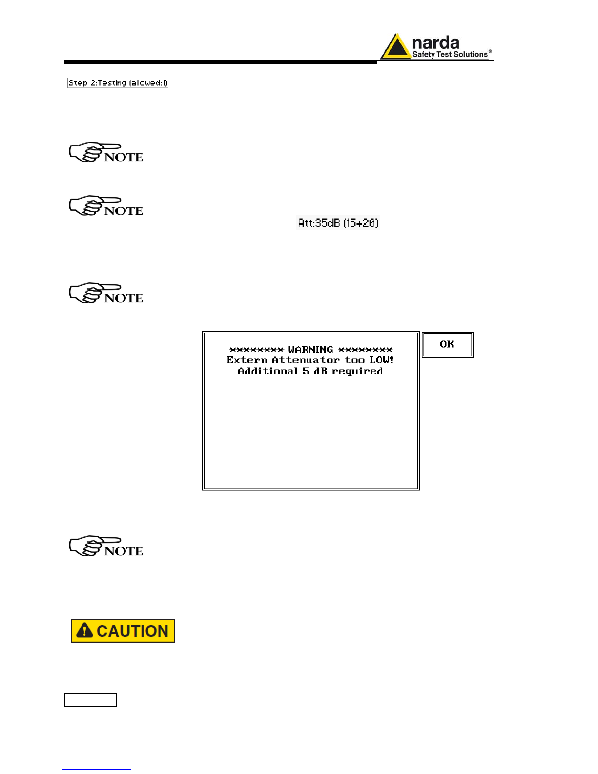
10-8 Click Mode Operating Instructions
After the Step 1 is completed, the Step 2 begins automatically, carrying out
the measurements vs Lq limit, or, in other words, performing the heart of
the test itself.
In brackets, it is reported the max clicks number allowed (25% of the clicks
measured during Step 1).
Step 3 and Step 4 are similar to Step 1 and 2 for the 500 kHz frequency.
Then Step 5 and Step 6 are similar to Step 4, for 1.4 MHz and 30 MHz
respectively, with same time duration and limit.
At the right upper corner of the screen, you can find the input attenuation
indication.
In the example above, the total attenuation is 35dB, divided in 15dB
internal and 20dB external. The value of the external attenuator can be
inserted into the main Settings page, as explained later in this chapter.
In certain conditions, the analyzer may judge the input attenuation is not
adequate (for example, when the limit is recalculated following up the Lq
value): in that case, a screen like the following appears, and requires
additional attenuation.
In most cases, it is enough to touch OK to adjust the input attenuation to
the optimum value and continue the test.
The total amount of available internal attenuation is 45 dB in Click mode,
because also the pulse limiter 10 dB pad is used.
The provided 20dB external attenuator should be adopted when at least
20dB more attenuation is required.
Please remember that the maximum input signal allowed is 7 V (137
dBμV), and that a click test may result in a potentially dangerous
condition for the input stage of the receiver.
Before to apply an unknown signal to PMM 9010 receiver, use an
oscilloscope or a wide band RF voltmeter to measure it.
If needed, add a coaxial attenuator to the input signal line (a 20dB
external attenuator is always provided with PMM 9010-Click Option).
 Loading...