


NIM-511 / NIM-513
Distributed by:
Air-Met Scientic Pty Ltd
Work with Confidence
Air-Met Sales/Service
P: 1800 000 744
F: 1800 000 774
E: sales@airmet.com.au
Air-Met Rental
P: 1300 137 067
E: hire@airmet.com.au
W: www.airmet.com.au
Narda Industrial Field Meter
Operating Manual

Narda Safety Test Solutions GmbH
Sandwiesenstraße 7
72793 Pfullingen, Germany
® Names and Logo are registered trademarks of Narda Safety Test Solutions GmbH
and L3 Communications Holdings, Inc. –
Trade names are trademarks of the owners.
This product is protected by the following
patents:
United States Patent US6084551
© 2009
Order no.: 2403/98.22
Edition: 01/09.11, A...
Previous edition: -
Subject to change.
Our normal guarantee and delivery terms
apply.
Printed in Germany

Contents
Contents
1 Useful information . . . . . . . . . . . . . . . . . . . . . . . . . . . . . . . . . . . . . . . . 1
1.1 Measuring electromagnetic fields . . . . . . . . . . . . . . . . . . . . . . . . . 2
1.2 About this instrument . . . . . . . . . . . . . . . . . . . . . . . . . . . . . . . . . . 2
Applications . . . . . . . . . . . . . . . . . . . . . . . . . . . . . . . . . . . . . . . . . 3
1.3 About this operating manual . . . . . . . . . . . . . . . . . . . . . . . . . . . . . 4
Characters and symbols used . . . . . . . . . . . . . . . . . . . . . . . . . . . 4
Terminology . . . . . . . . . . . . . . . . . . . . . . . . . . . . . . . . . . . . . . . . . 6
2 Safety instructions . . . . . . . . . . . . . . . . . . . . . . . . . . . . . . . . . . . . . . . . 7
2.1 Using this operating manual . . . . . . . . . . . . . . . . . . . . . . . . . . . . . 8
2.2 Proper use . . . . . . . . . . . . . . . . . . . . . . . . . . . . . . . . . . . . . . . . . . 8
2.3 Improper use. . . . . . . . . . . . . . . . . . . . . . . . . . . . . . . . . . . . . . . . . 8
2.4 Dangers from electromagnetic fields . . . . . . . . . . . . . . . . . . . . . . 9
Strong Fields. . . . . . . . . . . . . . . . . . . . . . . . . . . . . . . . . . . . . . . . . 9
Measurement Errors . . . . . . . . . . . . . . . . . . . . . . . . . . . . . . . . . . . 9
Probe is not operating properly. . . . . . . . . . . . . . . . . . . . . . . . . . . 9
2.5 Dangers when handling rechargeable batteries . . . . . . . . . . . . . 10
2.6 Dangers from AC adapter/charger . . . . . . . . . . . . . . . . . . . . . . . 10
3 Preparing the NIM-51x for use . . . . . . . . . . . . . . . . . . . . . . . . . . . . . . 11
3.1 Unpacking. . . . . . . . . . . . . . . . . . . . . . . . . . . . . . . . . . . . . . . . . . 12
Packaging . . . . . . . . . . . . . . . . . . . . . . . . . . . . . . . . . . . . . . . . . . 12
Items included. . . . . . . . . . . . . . . . . . . . . . . . . . . . . . . . . . . . . . . 12
Transport damage. . . . . . . . . . . . . . . . . . . . . . . . . . . . . . . . . . . . 12
After transport and storage . . . . . . . . . . . . . . . . . . . . . . . . . . . . . 13
3.2 Instrument overview . . . . . . . . . . . . . . . . . . . . . . . . . . . . . . . . . . 14
Narda NIM-51x i

Contents
3.3 Power supply . . . . . . . . . . . . . . . . . . . . . . . . . . . . . . . . . . . . . . . 16
Operation from rechargeable batteries . . . . . . . . . . . . . . . . . . . 16
Charge state and power source indicator . . . . . . . . . . . . . . . . . 18
3.4 Connecting the probe. . . . . . . . . . . . . . . . . . . . . . . . . . . . . . . . . 19
4 Measuring with the NIM-51x . . . . . . . . . . . . . . . . . . . . . . . . . . . . . . . 21
4.1 Avoiding measurement errors . . . . . . . . . . . . . . . . . . . . . . . . . . 22
Electrostatic charges . . . . . . . . . . . . . . . . . . . . . . . . . . . . . . . . . 22
Changes in temperature . . . . . . . . . . . . . . . . . . . . . . . . . . . . . . 22
Strong low frequency fields . . . . . . . . . . . . . . . . . . . . . . . . . . . . 23
4.2 Switching on. . . . . . . . . . . . . . . . . . . . . . . . . . . . . . . . . . . . . . . . 24
4.3 Displaying the instrument configuration . . . . . . . . . . . . . . . . . . . 24
4.4 Self test . . . . . . . . . . . . . . . . . . . . . . . . . . . . . . . . . . . . . . . . . . . 25
4.5 Setting the contrast . . . . . . . . . . . . . . . . . . . . . . . . . . . . . . . . . . 25
4.6 Overview of the display . . . . . . . . . . . . . . . . . . . . . . . . . . . . . . . 26
4.7 Selecting the result type. . . . . . . . . . . . . . . . . . . . . . . . . . . . . . . 26
ACT (Actual) . . . . . . . . . . . . . . . . . . . . . . . . . . . . . . . . . . . . . . . 27
MAX (Maximum) . . . . . . . . . . . . . . . . . . . . . . . . . . . . . . . . . . . . 27
AVG (Average) . . . . . . . . . . . . . . . . . . . . . . . . . . . . . . . . . . . . . . 27
SPATIAL (spatial average) . . . . . . . . . . . . . . . . . . . . . . . . . . . . . 28
4.8 Selecting the units . . . . . . . . . . . . . . . . . . . . . . . . . . . . . . . . . . . 29
4.9 Freezing a result . . . . . . . . . . . . . . . . . . . . . . . . . . . . . . . . . . . . 29
4.10 Changing the field type . . . . . . . . . . . . . . . . . . . . . . . . . . . . . . . 29
4.11 Switching off. . . . . . . . . . . . . . . . . . . . . . . . . . . . . . . . . . . . . . . . 30
ii NIM-51x Narda

Contents
5 Instrument maintenance . . . . . . . . . . . . . . . . . . . . . . . . . . . . . . . . . . 31
5.1 Cleaning the instrument . . . . . . . . . . . . . . . . . . . . . . . . . . . . . . . 32
5.2 Replacing / removing the batteries . . . . . . . . . . . . . . . . . . . . . . . 32
5.3 Disposal . . . . . . . . . . . . . . . . . . . . . . . . . . . . . . . . . . . . . . . . . . . 34
Rechargeable batteries. . . . . . . . . . . . . . . . . . . . . . . . . . . . . . . . 34
Instrument. . . . . . . . . . . . . . . . . . . . . . . . . . . . . . . . . . . . . . . . . . 35
5.4 Checking for proper operation . . . . . . . . . . . . . . . . . . . . . . . . . . 35
6 Specifications . . . . . . . . . . . . . . . . . . . . . . . . . . . . . . . . . . . . . . . . . . . 37
6.1 Display and Functions. . . . . . . . . . . . . . . . . . . . . . . . . . . . . . . . . 38
6.2 Measurement . . . . . . . . . . . . . . . . . . . . . . . . . . . . . . . . . . . . . . . 38
6.3 Uncertainty . . . . . . . . . . . . . . . . . . . . . . . . . . . . . . . . . . . . . . . . . 39
6.4 General specifications . . . . . . . . . . . . . . . . . . . . . . . . . . . . . . . . 39
6.5 Standards compliance . . . . . . . . . . . . . . . . . . . . . . . . . . . . . . . . 40
6.6 AC Adapter / Charger Unit . . . . . . . . . . . . . . . . . . . . . . . . . . . . . 40
6.7 CE Declaration of Conformity . . . . . . . . . . . . . . . . . . . . . . . . . . . 41
6.8 Declaration of origin . . . . . . . . . . . . . . . . . . . . . . . . . . . . . . . . . . 43
7 Ordering information . . . . . . . . . . . . . . . . . . . . . . . . . . . . . . . . . . . . . 45
7.1 NIM-511 and NIM-513 . . . . . . . . . . . . . . . . . . . . . . . . . . . . . . . . 46
7.2 Accessories . . . . . . . . . . . . . . . . . . . . . . . . . . . . . . . . . . . . . . . . 46
Index. . . . . . . . . . . . . . . . . . . . . . . . . . . . . . . . . . . . . . . . . . . . . . . . . . . 47
Narda NIM-51x iii

Contents
iv NIM-51x Narda

1 Useful information
This chapter contains basic information about measuring
electromagnetic fields and about using the NIM-51x.
1.1 Measuring electromagnetic fields (page 2)
1.2 About this instrument (page 2)
1.3 About this operating manual (page 4)
Narda NIM-51x 1

1 Useful information
1.1 Measuring electromagnetic fields
In today’s world, practically everyone lives and works in an
environment surrounded by technical equipment that generates electromagnetic fields. Our recognition of the problems
associated with such fields and our depth of information in
this area has increased as the effects of such fields on the
human body have been examined more closely. Various
authorities have long defined limit values designed to protect users from the dangers of exposure to such emissions.
1.2 About this instrument
The Narda Industrial Meters NIM-511 and NIM-513 combine an unprecedented ease of operation with powerful
measurement capabilities. It provides the industrial plant
manager and safety professional with an accurate and inexpensive solution for proving compliance with regulations
that cover exposure to RF radiation. Both models provide a
complete measurement system comprised of an extremely
easy to operate meter (NIM-510) and a probe (NIM-511 or
NIM-513) that contains sensors to measure both the electric
(E) and magnetic (H) field components of an electromagnetic wave.
The NIM-513 operates from 10 MHz to 42 MHz and is
adjusted to the reference calibration frequency at
27.12 MHz. The NIM-511 has a much broader sensor that
operates from 300 kHz to 100 MHz and is adjusted to the
reference calibration frequency at 13.56 MHz.
2 NIM-51x Narda

1.2 About this instrument
Applications
Major safety standards worldwide require that both the electric and the magnetic field components (E and H fields) be
measured for equipment operating below 300 MHz. Most
high power industrial equipment operates at one of the frequencies allocated for Industrial, Scientific, and Medical
(ISM) applications. Two ISM frequencies – 27.12 MHz and
13.56 MHz – are used extensively. The majority of heat
sealers and induction heaters operate at 27.12 MHz while
most semiconductor processing equipment operates at
13.56 MHz.
Examples:
• RF or High Frequency Heat Sealers
• Vinyl Welders
• Semiconductor Process Equipment
• Glass Deposition
• RF Induction Heating
• Dielectric Dryers and Heaters
• Plasma Generation Systems
RF energy can cause the body to be heated beyond its ability to thermally regulate itself. Since 1987 OSHA has had
the authority to cite employers for exceeding the limits specified by “state-of-the-art, scientific standards.” OSHA has
chosen the IEEE C95.1-2005 Standard for enforcement of
non-ionizing radiation safety. This IEEE standard includes
many changes from earlier standards and is considerably
more complex.
The Maximum Permissible Exposure (MPE) limits for Controlled Environments are:
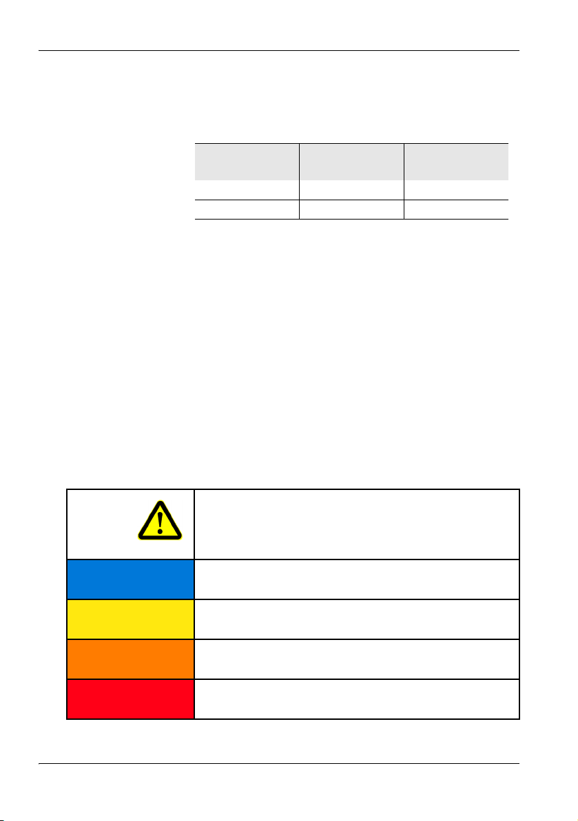
Table 1 IEEE C95.1-2005 exposure limits for controlled
environment
Frequency E Field
(mW/cm
13.56 MHz 4.89 54.4
27.12 MHz 1.22 13.6
40.68 MHz 1.00 6.04
2
)
H Field
(mW/cm
2
)
Narda NIM-51x 3
1 Useful information
For countries which follow the ICNIRP recommendations
the exposure limits are:
Table 2 ICNIRP 1998 Reference levels for occupational
exposure (extract)
Frequency f E Field
(V/m)
1 - 10 MHz 610 / f (f in MHz) 1.6 / f (f in MHz)
10 - 400 MHz 61 0.16
1.3 About this operating manual
Characters and symbols used
Various elements are used in this operating manual to indicate special meanings or particularly important passages in
the text.
Symbols and terms used in warnings
According to the American National Standard
ANSI Z535.6-2006, the following warnings, symbols, and
terms are used in this document:
H Field
(A/m)
The general danger symbol warns of risk of serious injury
when used with the signal words CAUTION, WARNING,
and DANGER. Follow all the instructions in order to avoid
injuries or death.
NOTICE
CAUTION
WARNING
DANGER
4 NIM-51x Narda
Indicates a danger that results in damage to or destruction
of the instrument.
Indicates a hazardous situation which, if not avoided,
could result in minor or moderate injury.
Indicates a hazardous situation which, if not avoided,
could result in death or serious injury.
Indicates a hazardous situation which, if not avoided, will
result in death or serious injury.
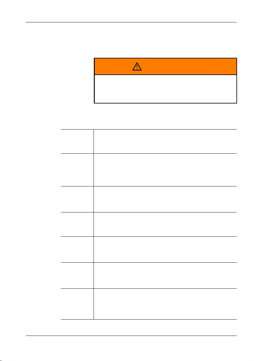
1.3 About this operating manual
Structure of warnings
All warnings are structured as follows:
SIGNAL WORD
Type and source of danger
Consequences of failure to observe warning
⇒ Instructions for preventing danger
Symbols and marks used in this document
! Important instruction
Indicates an instruction that must be followed to avoid danger.
Requirement
Indicates a requirement that must be met before the next
instruction can be carried out, e.g.
The instrument is switched off.
⇒ Instruction
Indicates a single instruction, e.g.
⇒ Switch the instrument on.
1.
2.
3.
ª Result
Bold type Control element
Blue type Cross reference (in PDF document only)
Sequence of instructions
Indicates a sequence of instructions that must be carried
out in the order given.
Indicates the result of carrying out an instruction, e.g.
ª The instrument starts a self test.
Indicates a control element on the instrument, e.g.
⇒ Press the MODE key
Indicates a cross reference to another part of the document. Click on the blue type in the PDF document to jump
directly to the cross reference.
Narda NIM-51x 5

1 Useful information
Terminology
Item Meaning
Battery Rechargeable battery
Dry battery Non-rechargeable battery
6 NIM-51x Narda

2 Safety instructions
This chapter contains important instructions on how to use
the NIM-51x safely. Please therefore read this chapter
carefully and follow the instructions closely.
2.1 Using this operating manual (page 8)
2.2 Proper use (page 8)
2.3 Improper use (page 8)
2.4 Dangers from electromagnetic fields (page 9)
2.5 Dangers when handling rechargeable batteries
(page 10)
2.6 Dangers from AC adapter/charger (page 10)
Narda NIM-51x 7

2 Safety instructions
2.1 Using this operating manual
! Carefully read this entire operating manual before you
start using the instrument.
! Keep this operating manual so that it is available to
everyone who uses the instrument, and ensure that this
operating manual is with the instrument if you pass it on to
a third party.
2.2 Proper use
The NIM-51x is designed to measure and evaluate electromagnetic fields.
! Only use the instrument for the purpose and under the
conditions for which it has been designed.
! In particular, observe the technical data given in the
“Specifications” on page 37.
Proper use also includes:
! observing any national accident prevention regulations at
the place of use,
! ensuring that the instrument is used only by appropriately
qualified and trained persons.
2.3 Improper use
The NIM-51x is not a warning device that gives active notice
of the existence of dangerous fields by means of a visible or
audible warning signal.
! Remember that this instrument is a measuring device, not
a warning device.
! Carefully observe the actual measurement displayed
when you are approaching an unknown field source.
! If in doubt, use an additional warning device such as
“RadMan” or “Nardalert XT”, available from Narda Safety
Te s t S ol u ti o ns .
8 NIM-51x Narda

2.4 Dangers from electromagnetic fields
2.4 Dangers from electromagnetic fields
Strong Fields
Very high field strengths can occur in the vicinity of
some radiation sources.
⇒ Do not cross or ignore safety barriers or markings.
⇒ Persons with electronic implants (e.g. heart pacemak-
ers) must avoid danger zones.
Measurement Errors
Metallic labels (stickers) affixed to the yellow sensor
area of the probe can lead to measurement errors, usually an underestimation of the electromagnetic field
strength.
⇒ Affix labels of any type only to the black probe shaft.
⇒ If the instrument malfunctions, take it out of service and
contact your Narda Service Center. The addresses are
listed at the end of this operating manual and on the Internet at http://www.narda-sts.com.
Probe is not operating properly
Possibly present high radiation values are not recognized.
⇒ Check probes for proper operation with a signal source
before using this measuring instrument.
Narda offers portable sources to accomplish this impor-
tant step (see “Accessories” on page 46).
⇒ Before beginning any RF radiation measurement, always
inform yourself of the frequencies and field strengths that
you could expect to encounter.
Narda NIM-51x 9

2 Safety instructions
2.5 Dangers when handling rechargeable batteries
When handled improperly, rechargeable batteries can
overheat, explode, or ignite.
⇒ Only use the NIM-51x with NiMH rechargeable batteries
(AA, Mignon).
⇒ Do not use dry batteries.
⇒ Do not replace individual batteries; always replace the
entire set.
⇒ Always use identical batteries.
⇒ Never touch both poles of the batteries simultaneously
with a metal object.
⇒ Make sure you insert the batteries correctly as shown on
the base of the battery compartment.
⇒ Always close the battery compartment immediately after
replacing batteries.
⇒ Never use the NIM-51x with the battery compartment
open.
2.6 Dangers from AC adapter/charger
You could experience electric shock from the AC
adapter/charger.
⇒ Do not use the instrument when the casing is damaged
because parts carrying dangerous voltages could be exposed.
⇒ Do not use an AC adapter/charger that has been moved
from a cold to a warm room, thereby forming condensation.
⇒ Only use the AC adapter/charger indoors and at temper-
atures between 0 °C and +40 °C.
The AC adapter/charger could be destroyed if the voltage specification on the AC adapter/charger does not
match the AC line voltage.
⇒ Only use the AC adapter/charger if the voltage specifica-
tion on the AC adapter/charger matches the AC line voltage.
10 NIM-51x Narda

3 Preparing the NIM-51x for
use
This chapter describes all you need to do before starting to
use the NIM-51x.
3.1 Unpacking (page 12)
3.2 Instrument overview (page 14)
3.3 Power supply (page 16)
3.4 Connecting the probe (page 19)
Narda NIM-51x 11

3 Preparing the NIM-51x for use
3.1 Unpacking
Packaging
The packaging is designed to be re-used as long as it has
not been damaged.
⇒ Keep the original packaging and use it whenever the in-
Items included
⇒ Check that all the following items have been delivered:
strument needs to be shipped or transported.
– NIM-510 Basic unit
– 2 x NiMH Mignon/AA batteries for NIM-510 (packaged
separately)
– Probe NIM-511 or NIM-513 (as ordered)
–Case
– AC Adapter / Charger
– Shoulder strap
– Operating manual
– Calibration certificate
Transport damage
NOTICE
Instrument/accessories damaged during
transportation
Using damaged instrument/accessories can lead to
subsequent damage.
⇒ Check the instrument and all accessories for damage
when you have unpacked them.
⇒ If the instrument is damaged, contact your Narda Ser-
vice Center.
The addresses of your Narda Service Center are listed at
the end of this operating manual and on the Internet at
http://www.narda-sts.com.
12 NIM-51x Narda

3.1 Unpacking
After transport and storage
NOTICE
Condensation on an instrument can lead to
damage
Condensation can form on an instrument that has
been stored at a low temperature when it is brought
into a warm room. It may be damaged if used.
⇒ Wait until all visible condensation has evaporated from
the instrument surface to avoid damaging the instrument.
Note: The instrument is not ready for use until it has
reached a temperature within the operating
range of -10 to +50 °C.
Narda NIM-51x 13

3 Preparing the NIM-51x for use
7
1
2
3
4
9
10
6a
6b
6
5
8
11
3.2 Instrument overview
14 NIM-51x Narda

1 Probe connector socket
2Display
3 Operating panel
Hold or Start / Stop button
Freezes the display value, or start / stop measurement for spatial measurements
Mode button
Selects the display mode for the measured values
Hold and Mode button simultaneously
Switches the field type between E-field and H-field display
Units button
Selects the display units
ON / OFF or Clear button
Switches the instrument on or off
Charge Charge state
Indicates the charge state (red = rapid charging, green = trickle charging)
Status Operating status
Indicates the instrument operating status:
• Green = normal operation
• Red = remote operation
• Flashing red =
– Firmware update
4 Rubber cover
5 Tripod bush
6 Electrical and optical connectors
6a AC Adapter / Charger
6b Optical connector (for service only)
7 Battery compartment (on back of instrument)
8Stand
3.2 Instrument overview
Probe
9 Probe head
10 Probe plug
11 Probe handle
Narda NIM-51x 15

3 Preparing the NIM-51x for use
3.3 Power supply
The power supply is normally taken from the batteries provided. You can use the AC Adapter / Charger supplied as an
alternative power source.
Note: We do not recommend that you operate the in-
Operation from rechargeable batteries
The rechargeable NiMH batteries for this device are
packaged separately. You must insert the batteries into the
device and then charge them up fully before using the
device. The charging cycle takes about 2 hours. Do not use
dry batteries in this device.
Improper pole positions
The batteries can explode and damage the instrument
if you put the batteries in the wrong way round.
⇒ Observe the positions of the positive and negative
poles marked in the battery compartment.
strument with the AC Adapter / Charger connected, as this can significantly degrade the
measurement performance of the NIM-51x. The
measurement accuracy figures given in the specifications cannot then be guaranteed.
NOTICE
Inserting the batteries
1. Open the battery compartment cover underneath the
device by undoing the two screws with a screwdriver or
the edge of a coin.
2. Take the NiMH batteries provided out of their protective
foil and insert them into the battery compartment. Make
sure you put them in the right way round. The positions
of the positive and negative poles are marked in the
battery compartment by "+" and " –" respectively. Match
the markings to the markings on the batteries.
3. Close the battery compartment cover and do up the two
screws again to secure it.
16 NIM-51x Narda

3.3 Power supply
Charging the batteries
If the device is probably not going to be used for several
weeks, it should be recharged before being stored to avoid
the possibility of deep discharge of the batteries. If storage
is likely to be for a period of more than two months, remove
the batteries from the device after recharging them.
Note: Deep discharge can significantly reduce the battery
capacity. This is indicated by unusually short
charging cycles. If this happens, the nominal
capacity can be restored by discharging and
recharging the batteries several times. Regeneration
usually takes four to five recharging cycles.
WARNING
Charging the batteries with wrong AC
Adapter / Charger
Overheating, explosion, or ignition of rechargeable
batteries/batteries or their surroundings
⇒ You must use only the AC Adapter / Charger supplied
to charge the batteries.
Note: A complete charge cycle takes about 2 hours
(with the instrument switched off).
Starting the charge cycle
The AC line voltage must match the operating voltage of
the AC Adapter / Charger.
1. Connect the AC Adapter / Charger to the charging
socket of the NIM-51x.
2. Connect the AC Adapter / Charger to the AC line.
ª The charge cycle starts.
ª The Charge LED glows red during the entire charge
cycle.
As soon as the batteries are fully charged, the AC Adapter /
Charger switches to trickle charge mode and the Charge
LED glows green.
Narda NIM-51x 17

3 Preparing the NIM-51x for use
Proper handling of rechargeable batteries
⇒ Observe the following precautions when handling re-
• Always handle the batteries with care.
• Do not drop or damage the batteries or expose them to
excessively high temperatures.
• Do not leave the batteries inside or outside the instrument
for more than one or two days in a very warm place (e.g.
in an automobile).
• Do not leave the discharged batteries in the unused
instrument for a long period of time.
• Do not store the batteries for more than six months without
discharging and recharging them in the meantime.
• Avoid deep discharging the batteries as this could cause
the cells to reverse polarity and make them useless.
Charge state and power source indicator
The battery charge state and the power source used are
indicated at the top right of the display:
Table 3 Charge state and power source indication
chargeable batteries:
Power is supplied by the rechargeable batteries.
• Continuous display: Charge level = 10%
• Flashing display: Charge level ≤ 5%
If the charge level drops to ≤ 5%, the instrument will
switch off automatically within a few minutes.
Power is supplied by the rechargeable batteries.
The charge level is indicated in 20% steps by black
bars within the battery symbol. The batteries are
fully charged when all five bars are shown.
Power is supplied by the AC Adapter / Charger.
The batteries are charged at the same time.
18 NIM-51x Narda

3.4 Connecting the probe
Probe is not operating properly
Possibly present high radiation values can not be recognized when a probe is defective.
⇒ Check probes for proper operation with a signal source
before using this measuring instrument.
Narda offers portable sources to accomplish this im-
portant step (see “Accessories” on page 46).
⇒ Before beginning any RF radiation measurement, al-
ways advise yourself of the frequencies and field
strengths that you could expect to encounter.
Wrong handling of the probe
Damage of the probe head
⇒ Always hold the probe at the probe handle (11).
3.4 Connecting the probe
WARNING
NOTICE
Connecting the probe
Make sure the guide lug on the probe plug (10) is
pointing towards the front of the instrument.
⇒ Push the probe plug (10) straight down into the probe
socket (1) and tighten the threaded coupling using your
thumb and forefinger. Never tighten the coupling using
pliers or other tools.
Disconnecting the probe
⇒ Undo the threaded coupling using your thumb and fore-
finger and then pull the probe upwards to release it.
Narda NIM-51x 19

3 Preparing the NIM-51x for use
20 NIM-51x Narda

4 Measuring with the NIM-51x
This chapter describes how to make measurements using
the NIM-51x.
4.1 Avoiding measurement errors (page 22)
4.2 Switching on (page 24)
4.3 Displaying the instrument configuration (page 24)
4.4 Self test (page 25)
4.5 Setting the contrast (page 25)
4.6 Overview of the display (page 26)
4.7 Selecting the result type (page 26)
4.8 Selecting the units (page 29)
4.9 Freezing a result (page 29)
4.10 Changing the field type (page 29)
4.11 Switching off (page 30)
Narda NIM-51x 21

4 Measuring with the NIM-51x
4.1 Avoiding measurement errors
The measurement result can be falsified by external
influences when measuring electromagnetic fields.
Considerable measurement deviations can occur under
certain circumstances, particularly when measuring low
field strengths. The following tips may be of assistance in
recognizing sources of interference so as to avoid
measurement errors. The following factors can affect the
measurement result:
• Electrostatic charges
• Changes in temperature
• Strong low frequency fields (e.g. due to high tension lines)
Electrostatic charges
The following effect will be noted with all field strength
meters: If you move the probe quickly, excessive field
strength values will be displayed which do not reflect the
actual field conditions. This effect is caused by electrostatic
charges.
The NIM has been designed in a way that minimizes this
effect. However, if you move the probe very quickly, field
strengths on the order of a few V/m can be displayed.
Recommendation: Hold the device steady during the measurement. Delete the
stored maximum values and average values by pressing
Clear before using the MAX or AVG result types. Do not
touch the probe at any time during the measurement.
Changes in temperature
Ambient temperature changes as well as warming by direct
sunlight will create offset voltages that may impact the
measurement result. Zeroing eliminates offset voltages
within the instrument only. Offset voltages caused by the
probe can not be eliminated.
Recommendation: Try to avoid heating caused by direct sunlight during
measurements . Consider an adequate settling time for
stabilization of the probe in case of temperature changes.
22 NIM-51x Narda

3.4 Connecting the probe
Strong low frequency fields
The result display when measuring high frequency
electromagnetic fields can be falsified by low frequency
fields. Wideband probes will detect signals even if the
frequency is well outside the specified measurement range
(out-of-band attenuation is 20 dB/decade). Very high field
strengths of several thousand V/m can occur in the vicinity
of high tension lines. The NIM-51x would therefore register
several V/m.
Recommendation: Thoroughly inspect every measurement location before any
measurement and make a note of any possible sources of
interference, such as high tension lines in the vicinity. Keep
a critical eye on any possible increase in the minimum
display value (noise floor) which may indicate interfering
factors. Increase the distance from the source of low
frequency interference, if possible.
Narda NIM-51x 23

4 Measuring with the NIM-51x
4.2 Switching on
You can switch the instrument on as soon as you have prepared it for use.
⇒ Press the ON/OFF button to switch the instrument on.
ª The instrument displays the instrument settings and
performs a self test.
4.3 Displaying the instrument configuration
The factory configuration of the instrument is displayed after
the instrument is turned on. The configuration can't be
changed by the user.
⇒ Press the Hold button to “freeze” the display of settings
or to resume measurements.
ª After a few seconds, the self test starts.
The configuration settings are explained briefly below.
AUTO-ZERO 15 minutes
This value determines how often automatic zeroing is performed.
AUTO-OFF 15 minutes
To prevent discharging the batteries unnecessarily, the
instrument will be switched off automatically after 15 minutes without activity.
BACKLIGHT 10 seconds
The display backlight is activated each time you press a button and switches off after a specified time to prevent discharging the batteries unnecessarily.
AVG TIME 6 minutes
This value specifies the time period over which the results
are averaged.
24 NIM-51x Narda

SPATIAL Continuous
This item displays the measurement method for determining
the spatial average. The measurement values are recorded
and averaged continuously when started until the HOLD
button is pressed.
More information on spatial averaging is found under “SPA-
TIAL (spatial average)” on page 28.
UNIT The UNIT item displays the last unit used.
4.4 Self test
LIMIT FLAT/
LIMIT SHAP
ALARM Not used
Not used
4.4 Self test
The self test takes a few seconds. During this time, the firmware version is also displayed. If the test is successful, the
message OK is displayed on the screen.
If an error message is displayed:
⇒ Press the ON/OFF button again to switch the instrument
off and then switch it on again.
If an error message is displayed again:
⇒ Switch the instrument off and contact your nearest
Narda Service Center.
4.5 Setting the contrast
You can change the display contrast dependent of the environment lighting in order to achieve optimal instrument
read-out.
The instrument is turned on and the self test is finished.
⇒ Press the ON/OFF button and Mode button
simultaneously to increase the contrast.
Narda NIM-51x 25

4 Measuring with the NIM-51x
13
4
5
6
78
2
⇒ Press the ON/OFF button and Units button
simultaneously to decrease the contrast.
4.6 Overview of the display
The image below shows the items that can be displayed
during a measurement.
1 Probe model
2 Measured value “frozen” (hold) / Zero displays during
zeroing / Elapsed time counter in SPATIAL mode
3 Battery charge status
4 Result type
5 Measured value
6 Measured value units
7 Field type E-field or H-field (more information on
page 29)
8 Value is outside probe measurement range
4.7 Selecting the result type
The NIM-51x can display the results in various ways:
• ACT (Actual) (page 27)
• MAX (Maximum) (page 27)
• AVG (Average) (page 27)
• SPATIAL (spatial average) (page 28)
These different result display modes are described in the
sections indicated above.
To select a result type:
⇒ Press the Mode button repeatedly until the desired result
type is displayed.
26 NIM-51x Narda

4.7 Selecting the result type
Remaining time display
ACT (Actual)
The actual field strength value measured at the moment is
displayed.
If the measured value is outside the instrument’s measurement range or if it cannot be shown correctly on the display,
appropriate symbols are displayed on the left to indicate
this.
Table 4 Symbols indicating value outside range limits.
The measured value is below the
measurement range of the probe.
The measured value is above the
measurement range of the probe.
The measured value is above the
instrument display range.
MAX (Maximum)
The maximum value measured during the current measurement is always displayed. Measurement of the maximum
value starts as soon as you switch on the instrument. The
measured value memory is cleared if you change the probe
or press the Clear button.
⇒ Press the Clear button to reset the maximum value and
restart the measurement.
AVG (Average)
The following averages are determined:
• Linear average of power values (e.g. W/m
• Root mean square (RMS) of field strength values
(e.g. V/m or A/m)
Both types of average give the same result. The averaging
process conforms to current safety standards for high frequency fields and normally takes place over a period of
6 minutes. The units of the measured value can be switched
at any time without affecting the results already averaged.
Narda NIM-51x 27
2
or mW/cm2)

4 Measuring with the NIM-51x
The period of time over which the average is taken is
6 minutes. The progress of forming the average is shown by
the remaining time display. The time counts down to 0.
When the averaging time has elapsed, the remaining time
display is no longer shown.
⇒ Press the Clear button to reset the average value and re-
SPATIAL (spatial average)
The spatial average function allows you to determine the
spatial average value of the field strength. This measurement mode is used, for example, to determine the degree to
which the human body is exposed to electromagnetic radiation.
Measurement values are recorded and averaged continuously while the probe is moved through the area of interest.
This allows you to measure the field strength affecting an
entire room.
To measure spatially averaged values
1. Press the Mode button repeatedly until the result type
2. Press the Hold button to start the measurement.
3. Move the probe smoothly through the volume to be
4. To perform a further measurement, press the Hold
Note: To help you move the probe smoothly, an audible
start the measurement.
SPATIAL is displayed.
ª The elapsed measurement time is shown top left in
the display.
measured and then press the Hold button again to end
the measurement.
ª The spatial average value is shown on the display.
button again. This automatically resets the last average
value.
signal is output once every second.
28 NIM-51x Narda

4.8 Selecting the units
The NIM-51x can display the results in several different
measurement units.
•V/m
•A/m
2
•W/m
•mW/cm
To select the units
⇒ Press the Units button repeatedly until the desired units
Note: Field strength units (V/m or A/m) will change au-
2
are displayed.
tomatically when selecting another field type
(V/m for E-field, A/m for H-field).
4.9 Freezing a result
1. Press the Hold button to hold the measurement value
that is currently displayed.
2. Press the Hold button again to resume measuring.
4.8 Selecting the units
4.10 Changing the field type
The NIM probe can measure electric (E) as well as magnetic (H) fields. You will need to select the field type on the
instrument. The field type is shown at the bottom left of the
display.
To change the field type
⇒ Press the Hold and Mode buttons simultaneously (tog-
gle function).
Narda NIM-51x 29

4 Measuring with the NIM-51x
4.11 Switching off
To switch the instrument off
⇒ Press and hold down the ON/OFF button for about three
seconds.
ª The instrument switches off.
30 NIM-51x Narda

5 Instrument maintenance
This chapter describes how to clean the instrument, replace
the batteries, dispose the instrument and check the instrument for proper operation.
5.1 Cleaning the instrument (page 32)
5.2 Replacing / removing the batteries (page 32)
5.3 Disposal (page 34)
5.4 Checking for proper operation (page 35)
Narda NIM-51x 31

5 Instrument maintenance
5.1 Cleaning the instrument
NOTICE
Damage to the instrument from liquids
The instrument may be damaged or destroyed if liquids are allowed to get inside the casing.
⇒ Make sure that no liquid gets inside the instrument.
NOTICE
Solvents
Solvents can corrode the surfaces of basic unit,
probe and AC Adapter / Charger.
⇒ You must not use solvents to clean the basic unit,
probe, and AC Adapter / Charger.
Cleaning the instrument:
1. Use a soft cloth to clean the instrument. You can use
lukewarm water to which a little detergent solution has
been added as a cleansing agent.
2. To prevent streaks and spots, wipe off the instrument
with a dry cloth while it is still damp.
5.2 Replacing / removing the batteries
The rechargeable batteries have a useful life of about 1000
charge cycles or 3 years (whichever occurs soonest).
32 NIM-51x Narda

5.2 Replacing / removing the batteries
Replace the batteries if the operating time is significantly
reduced although the batteries are fully charged.
WARNING
Improper replacement of batteries
Overheating, explosion, or ignition of rechargeable
batteries/batteries or their surroundings
⇒ Only use the NIM-51x with NiMH rechargeable batter-
ies (AA, Mignon).
⇒ Do not use dry batteries.
⇒ Do not replace individual batteries; always replace the
entire set.
⇒ Always use identical batteries.
WARNING
Short circuiting the batteries
Overheating, explosion, or ignition of rechargeable
batteries or their surroundings
⇒ Never touch both poles of the batteries simultaneously
with a metal object.
⇒ Always close the battery compartment immediately af-
ter replacing batteries.
⇒ Never use the NIM-51x with the battery compartment
open.
WARNING
Reverse charging of rechargeable batteries
NiMH batteries can explode if you charge them with
reversed poles.
⇒ Make sure you insert the batteries correctly as shown
on the base of the battery compartment.
Narda NIM-51x 33

5 Instrument maintenance
Replacing the batteries
1. Switch off the instrument and disconnect it from all other
devices (AC Adapter / Charger, optical cable).
2. Open the battery compartment on the back of the
instrument.
3. Remove the old batteries and dispose of them according
to the waste disposal ordinances applicable in your
country.
4. Insert the new batteries.
Make sure you insert them the right way round according
to the diagram on the base of the battery compartment.
5. Close the battery compartment.
6. Connect the AC Adapter / Charger and charge the
batteries (a complete charge cycle takes about 2 hours).
5.3 Disposal
Rechargeable batteries
Do not dispose of the batteries with the normal household
waste. You should dispose of old batteries that are no longer
required in accordance with the waste disposal ordinances
in your country.
34 NIM-51x Narda

5.4 Checking for proper operation
Instrument
This product is subject to European Guideline 2002/96/EC
governing the disposal of waste electrical and electronic
equipment (WEEE).
Do not dispose of this instrument with the normal household
waste. You should dispose of it in accordance with the waste
disposal ordinances in your country.
Within the European Union, all electronic measuring systems purchased from Narda after 13th August 2005 can be
returned when they reach the end of their useful life. The
measuring systems that come under this regulation or the
documents that accompany them are clearly marked with
the symbol of a garbage bin crossed out with black lines.
You can obtain further information from your local Narda
Sales Partner or at http://www.narda-sts.com.
5.4 Checking for proper operation
WARNING
Probe is not operating properly
Possibly present high radiation values are not recognized.
⇒ Check probes for proper operation with a signal source
before using this measuring instrument.
Narda offers portable sources to accomplish this important step (see “Accessories” on page 46).
⇒ Before beginning any RF radiation measurement, al-
ways advise yourself of the frequencies and field
strengths that you could expect to encounter.
Narda NIM-51x 35

5 Instrument maintenance
Performing a function test:
1. Connect the probe to the instrument (see “Connecting
the probe” on page 19).
2. Switch the instrument on and immediately thereafter
press and hold down the Units key for 2-3 seconds to
activate the probe function test.
ª After the self test the measured field strength will be
displayed separately for all 3 input channels
(Ch1...3).
3. Bring an appropriate signal source (see “Accessories”
on page 46) near the probe head.
4. Switch the signal source on.
ª The Ch1...3 display increases: Function test OK
Briefly press the ON/OFF button to change to the
measurement mode.
ª The Ch1...3 display does not increase: Function test
not OK.
Do not use the probe any more. Contact the
responsible service center.
Note: Do not use this function test for measurements.
This test is suitable only for checking probes.
All 3 channels must respond to the field source.
Ch1 is related to the E field sensors.
Ch2...3 are relatedto the H field sensors and will
show identical values.
36 NIM-51x Narda

6 Specifications
This chapter lists the specifications of the NIM-51x.
6.1 Display and Functions (page 38)
6.2 Measurement (page 38)
6.3 Uncertainty (page 39)
6.4 General specifications (page 39)
6.5 Standards compliance (page 40)
6.6 AC Adapter / Charger Unit (page 40)
6.7 CE Declaration of Conformity (page 41)
6.8 Declaration of origin (page 43)
Narda NIM-51x 37

6 Specifications
6.1 Display and Functions
Display type Transflective LCD, monochrome, LED backlight
Display size 4 cm (1.5"), 128 x 64 dots
Refresh rate 400 ms 400 ms
Result display E-field or H-field value (selectable, 4 digits)
Result units mW/cm
Result types (isotropic, RSS) ACT: Display of the actual value
MAX: Holds the maximum of all measured values
AVG: Display of the result averaged over 6 minutes
SPATIAL: Display of the spatially averaged result
Hold Hold button to freeze the value that is currently displayed
Zeroing Automatic zeroing after power-on and repetitively every 15 min
2
, W/m2, V/m, A/m
6.2 Measurement
Field type Electric (E-) field and magnetic (H-) field with switchable display
Frequency range NIM-511: 300 kHz to 100 MHz
Measurement range (True RMS) E-field: 0.1 to 100 mW/cm
H-field: 0.2 to 200 mW/cm
CW damage level 50 W/cm
Sensor type Two diode based systems for E-field and H-field
Directivity Isotropic (Tri-axial)
Readout mode / spatial assessment
NIM-513: 10 MHz to 42 MHz
2
(20 to 614 V/m)
2
(0.073 to 2.3 A/m)
Combined 3-axes (RSS)
2
38 NIM-51x Narda

6.3 Uncertainty
6.3 Uncertainty
NIM-511
Flatness of frequency response
(Calibration uncertainty not included)
NIM-513
Flatness of frequency response
(Calibration uncertainty not included)
Calibration uncertainty ±0.5 dB
Linearity
2
(Referred to 10 mW/cm
Isotropic response ±1 dB
Temperature response +0.8 dB (10 °C to 40 °C)
)
E-field: ±0 dB @ 13.56 MHz
±1.5 dB (300 kHz to 100 MHz)
H-field: ±0 dB @ 13.56 MHz
±0.6 dB (300 kHz to 100 MHz)
E-field: ±0 dB @ 27.12 MHz
±1.0 dB (10 MHz to 42 MHz)
H-field: ±0 dB @ 27.12 MHz
±0.6 dB (10 MHz to 42 MHz)
NIM-511 calibration frequencies 0.5/ 13.56/ 27.12/ 90 MHz
NIM-513 calibration frequencies 13.56/ 27.12/ 40.68 MHz
±1 dB (0.5 to 2 mW/cm2)
±0.5 dB (2 to 100 mW/cm
6.4 General specifications
Recommended calibration interval 24 months
MTBF >10 years (basic unit with probe)
Batteries Standard rechargeable NiMH batteries,
Operating time approx. 22 hours
Charging time 2 hours
Battery status indicator 100%, 80%, 60%, 40%, 20%, 10%, low (<5%)
Temperature range Operational: -10 °C to +50 °C
Humidity 5 to 95% relative humidity @ ≤28 °C, no condensation
≤26 g/m³ absolute humidity (IEC 60721-3-2 class 7K2)
Immunity to radiated electromagnetic fields 200 V/m (100 kHz to 60 GHz)
Size
Meter (h x w x d)
Probe
Cable
Weight
Meter
Probe
Accessories
(included)
Non-operational (transport): -30 °C to +70 °C
rigid shell case, AC adapter/charger, shoulder strap,
2 x AA (Mignon) type, 2500 mAh
1.5” x 2.0” x 8.1” (38 x 52 x 205 mm)
16 inches long (410 mm)
44 inches long (1.1 m)
0.66 lbs (300 g)
0.68 lbs (310 g)
operating manual, calibration certificate
2
)
Narda NIM-51x 39

6 Specifications
6.5 Standards compliance
Climatic Storage 1K3 (IEC 60721-3) extended to -10 °C to +50 °C
Transport 2K4 (IEC 60721-3) restricted to -30 °C to +70 °C
Operating 7K2 (IEC 60721-3)
Mechanical Storage 1M3 (IEC 60721-3)
Transport 2M3 (IEC 60721-3)
Operating 7M3 (IEC 60721-3)
Ingress Protection IP 42 (IEC 60529)
ESD and EMC EN 61326:2006
Safety EN 61010-1:2002
CE (European Union) Ye s
for the basic unit extended to -10 °C to +50 °C
6.6 AC Adapter / Charger Unit
AC line voltage range 100 V to 240 V AC
Nominal AC line frequency
range
Output voltage 9VDC
Maximum output current 1.5 A
Temperature range
•Storage
• Operation
50 Hz to 60 Hz
-40°C to +70°C
0°C to +40°C
40 NIM-51x Narda

6.7 CE Declaration of Conformity
6.7 CE Declaration of Conformity
Narda NIM-51x 41

6 Specifications
42 NIM-51x Narda

6.8 Declaration of origin
Country of origin: Germany
6.8 Declaration of origin
Narda NIM-51x 43

6 Specifications
44 NIM-51x Narda

7 Ordering information
This chapter lists the ordering information for the NIM-51x
and accessories.
7.1 NIM-511 and NIM-513 (page 46)
7.2 Accessories (page 46)
Narda NIM-51x 45

7 Ordering information
7.1 NIM-511 and NIM-513
NIM-511 Industrial Field Meter (0.3 to 100 MHz) 2400/511
NIM-513 Industrial Field Meter (10 to 42 MHz) 2400/513
NIM-511 and NIM-513
• NIM-510 Basic unit (2403/02)
• E/H Field Probe NIM-511 (2402/15) or E/H Field Probe NIM-513 (2402/13)
• Hard case
• Power supply, 9 VDC, 100 V - 240 VAC (2259/92.06)
• Shoulder strap, 1 m (2244/90.49)
• Operating manual
• Certificate of calibration
include:
7.2 Accessories
Test generator, 27 MHz, hand-held 2244/90.38
Protective pouch for the basic unit 2403/90.01
46 NIM-51x Narda

Index
Index
A
AC adapter/charger 10
Dangers from 10
ACT (Actual) 27
After transport and storage 13
Audible signal 28
AUTO-OFF 24
AUTO-ZERO 24
AVG (Average) 27
AVG TIME 24
B
BACKLIGHT 24
Batteries
Dangers from 18
Disposal of 34
Replacing / removing 32
C
CE Declaration of Conformity 41
Changing the field type 29
Charge state indicator 18
Checking for proper operation 35
Cleaning 32
Contrast setting 25
D
Declaration of origin 43
Display backlight 24
Disposal 34
I
Improper use 8
Instrument
Configuration 24
Function testing 35
Overview 14
Items included 12
M
MAX (Maximum) 27
Measuring
Freezing a result 29
values continuously 28
O
Operation from rechargeable
batteries 16
Ordering information 45
Overview of the display 26
P
Packaging 12
Probe
connecting 19
Function testing 35
Proper use 8
R
Rechargeable batteries
Proper handling of 18
E
Electromagnetic fields
Dangers from 9
Error message 25
F
Function testing 35
Narda NIM-51x 47

Index
S
Safety instructions 7
AC adapter/charger 10
Electromagnetic fields 9
Rechargeable batteries 10
Selecting the result type 26
Selecting the units 29
Self test 25
Setting contrast 25
SPATIAL 25
Spatial average 28
Specifications 37
Switching off 30
Switching on 24
Symbols and marks 5
, 28
T
Terminology 6
Transport and storage 13
Transport damage 12
U
UNIT 25
Unpacking 12
48 NIM-51x Narda


Narda Safety Test Solutions GmbH
Sandwiesenstraße 7
72793 Pfullingen, Germany
Phone: +49 7121-9732-777
Fax: +49 7121-9732-790
E-mail: support@narda-sts.de
www.narda-sts.com
Narda Safety Test Solutions
435 Moreland Road
Hauppauge, NY 11788, USA
Phone: +1 631-231-1700
Fax: +1 631-231-1711
E-mail: NardaSTS@L-3COM.com
www.narda-sts.us
Narda Safety Test Solutions Srl
Via Leonardo da Vinci, 21/23
20090 Segrate (Milano), Italy
Phone: +39 02 2699871
Fax: +39 02 26998700
E-mail: support@narda-sts.it
www.narda-sts.it
2403/98.22
01/09.11, A...
English
 Loading...