

Page 1

NARDA
Safety
Test
Solutions
S.r.l. Socio Unico
http://www.narda-sts.it
Sales & Support:
Via Leonardo da Vinci, 21/23
20090 Segrate (MI) Tel.: +39 02 2699871
Fax: +39 02 26998700
AMS-8063
AREA MONITOR SYSTEM
ITALY
Manufacturing Plant:
Via Benessea, 29/B
17035 Cisano sul Neva (SV)
Tel.: +39 0182 58641
Fax: +39 0182 586400
User’s Manual
AMS-8063/00
AMS-8063/01
AMS-8063/02
SERIAL NUMBER OF THE INSTRUMENT
You can find the serial number on the side of the metal bracket located under the
baseplate, on the side of the Power pack and on the side of the Solar panels.
Serial number is in the form: 000XY00000.
The first three digits and the two letters are the Serial Number prefix, the last five
digits are the Serial Number suffix. The prefix is the same for identical instruments, it
changes only when a configuration change is made to the instrument.
The suffix is different for each instrument.
Document AMS8063EN-71005-1.22 – Copyright © NARDA 2017
Page 2

NOTE:
® Names and Logo are registered trademarks of Narda Safety Test Solutions GmbH and L3 Communications
Holdings, Inc. – Trade names are trademarks of the owners.
If the instrument is used in any other way than as described in this User’s Manual, it
may become unsafe.
Before using this product, the related documentation must be read with great care and fully understood to familiarize
with all the safety prescriptions.
To ensure the correct use and the maximum safety level, the User shall know all the instructions and
recommendations contained in this document.
In accordance with the IEC classification, the power supply of this product meets requirements Safety Class II and
Installation Category II (having double insulation and able to carry out mono-phase power supply operations).
It complies with the requirements of Pollution Class II (usually only non-conductive pollution). However,
occasionally it may become temporarily conductive due to condense on it.
The information contained in this document is subject to change without notice.
EXPLANATION OF ELECTRICAL AND SAFETY SYMBOLS :
You now own a high-quality instrument that will give you many years of reliable service.
Nevertheless, even this product will eventually become obsolete. When that time comes, please
remember that electronic equipment must be disposed of in accordance with local regulations.
This product conforms to the WEEE Directive of the European Union (2002/96/EC) and belongs to
Category 9 (Monitoring and Control Instruments). You can return the instrument to us free of
charge for proper environment friendly disposal. You can obtain further information from your
local Narda Sales Partner or by visiting our website at www.narda-sts.it .
This product is a Safety Class III instrument according to IEC classification
and has been designed to meet the requirements of EN61010-1 (Safety
Requirements for Electrical Equipment for Measurement, Control and
Laboratory Use).
Warning, danger of electric shock
Read carefully the Operating Manual and its
instructions, pay attention to the safety symbols
Earth Protection
KEY TO THE SYMBOLS USED IN THIS DOCUMENT:
The DANGER sign draws attention to a serious risk to a person’s safety,
which, if not avoided, will result in death or serious injury. All the
precautions must be fully understood and applied before proceeding.
The WARNING sign indicates a hazardous situation, which, if not avoided,
could result in death or serious injury. All the precautions must be fully
understood and applied before proceeding.
The CAUTION sign indicates a hazardous situation, which, if not avoided,
could result in minor or moderate injury.
The NOTICE sign draws attention to a potential risk of damage to the
apparatus or loss of data.
The NOTE sign draws attention to important information.
Earth
Unit Earth Connection
Equipotential
II Note and symbols
Page 3

Contents
Safety requirements and instructions…..........……........
EC Declaration of Conformity .........................................
1 General information Page
1.1 Documentation..............................................................
1.2 Introduction ……………....................…........................
1.3 Standard accessories ……………………………….......
1.3.1 Standard accessories AMS-8063-00…………..…….
1.3.2 Standard accessories AMS-8063-01…………..…….
1.3.3 Standard accessories AMS-8063-02…………..…….
1.4 Optional accessories…………………………………….
1.5 AMS-8063…………………………………………………
1.6 Main specifications……………………………………….
1.7 EHP-8063……………….….………………………..……
1.8 Support pole………………………………………………
2 Installation and use
Page
2.1 Introduction..................................................................
2.2 Initial inspection............................................................
2.3 Working environment...................................................
2.4 Return for repairs……..................................................
2.5 Cleaning………………..................................................
2.6 Installation and use.………………………………………
2.6.1 Installation of AMS-8063-00…………………..………
2.6.2 Installation of AMS-8063-01…………………..………
2.6.3 Installation of AMS-8063-02…………………..………
2.6.4 Supporto base, feet and pole …………….………..…
2.6.5 Solar panels (AMS-8063-00 and AMS-8063-01 only)
2.6.5.1 Solar panels mounting kit ………….……………….
2.6.5.2 Installation steps ……………………...……………..
2.6.5.3 Install the Solar panels to the Support base ……...
2.6.5.4 Solar panels wiring and fuse …………...………….
2.6.6 Battery pack wiring and fuse (AMS-8063-02 only)….
2.6.7 Baseplate mounting …………………………………...
2.6.8 Radome opening ………..…………………………..…
2.6.9 Battery pack power cable….………..………………...
2.6.10 10 Led LEDs 8063-Shutter status…………………..
2.6.11 Led WiFi converter status (AMS-8063-00 only)…..
2.6.12 Switch EHP-8063 on …….………….……………….
2.6.13 Led EHP-8063 status……………….………………..
2.6.14 AMS-8063-02 Interface box…………………………
2.6.15 Radome mounting………………….…………………
2.6.16 Bags ………….………………………………………..
2.6.17 Battery charging …….……………………………..…
2.6.18 External power supply.…….…………………………
2.7 AMS-8063-00 Operating principle ……….…………….
2.8 AMS-8063-01 Operating principle ……….…………….
2.9 AMS-8063-02 Operating principle ……….…………….
Page
VI
VII
1-1
1-1
1-2
1-2
1-3
1-4
1-5
1-6
1-7
1-9
1-10
2-1
2-1
2-1
2-1
2-2
2-2
2-3
2-4
2-5
2-6
2-8
2-8
2-9
2-10
2-13
2-15
2-17
2-18
2-19
2-20
2-20
2-20
2-20
2-21
2-22
2-22
2-23
2-26
2-28
2-29
2-30
Contents III
Page 4

3 8063SW02 User’s guide Page
3.1 Introduction ………….........................................…......................
3.2 Hardware requirements …………………………………………….
3.3 Use of the Software 8063SW02…………….………....................
3.4 Software installation …….…………………………………….........
3.5 USB-RS232 Adapter (optional) or AMS-8063-02 Interface box..
3.6 Software 8063SW02 COM port settings ………………………….
3.7 AMS-8063 Delay command setting .....................…...................
3.8 AW5500 Access point installtion (AMS-8063-00 only)………….
3.9 STE02W Wifi Serial Converter installation (AMS-8063-00 only)
3.10 Starting the program ………………………….............................
3.11 Main window …………………………………………….………….
3.11.1 Tool bar……..…………………………………………………….
3.11.2 Setting menu …………………………………………………….
3.11.3 Option……………………………………………………………..
3.11.3.1 Aspect…………………………………………………………..
3.11.3.2 Sort by date…………………………………………………….
3.11.4 Settings……………………………………………………………
3.11.4.1 Frequency Table……………………………………………….
3.11.4.2 Measure…………………………………………………………
Table Mode……………………………………………………….………
AVG/RMS……………………………………………………….…...……
Spectrum Mode…………………………………………………………..
Preamplifier………………………………………………….……………
Trace……………………………………………………………….……...
Text file Separator…………………………………………….…………
Save Bitmap/jpg………….…………………………………….…….....
OK/Default/Cancel………………………………………………………
3.11.5 Station control panel……………………………………………
3.11.6 File………………………………………………………………..
3.11.6.1 Info………………………………………………………..........
3.11.6.2 Save Panel…………………………………………………….
3.11.6.3 Open Panels…………………………………………………..
3.11.7 SCAN……………………………………………………………..
3.11.8 EXECUTE………………………………………………………..
3.11.9 8063SW02 Operating principle………………………………..
3.12 Uninstalling Software ……………………………………………..
3.13 Uninstalling the driver of RS232-USB adapter (optional)……..
3-1
3-1
3-2
3-3
3-7
3-8
3-9
3-9
3-12
3-13
3-15
3-16
3-16
3-17
3-17
3-18
3-19
3-19
3-22
3-23
3-23
3-24
3-25
3-25
3-25
3-26
3-26
3-27
3-28
3-28
3-28
3-29
3-30
3-32
3-35
3-36
3-37
4 Data display Page
4.1 Introduction......…...............................…….................................
4.2 Calendar....................................................….............................
4.2.1 Data window..................................................…......................
4.3 Data display...............................................…..…..…..................
4.3.1 Main commands ….……………………………………………….
4.3.1.1 Open Scan………………………………………………………
Data folder….…………………………………………………………….
Structure of the .TXT file………………………………….…………….
Structure of the .JPG, .BMP and .PCM file…………………………..
Structure of the Table.mode.txt file……………………………………
Events folder………….………………………………………………….
5 AMS-8063/WMK Wall Mounting Kit
5.1 Introduction ……………………………….……….…….................
5.2 Initial inspection……… ……….............................…...................
5.3. Working environment………………………………………………
5.4 Return for repair…………………………………………................
5.5. Cleaning……………………………………………………………..
5.6 Installation…………………………………………………………….
6 Packaging Instructions
6.1 Introduction ……………………………….……….…….................
6.2 Packaging Instructions ……….............................…....................
4-1
4-1
4-1
4-4
4-4
4-4
4-4
4-6
4-7
4-8
4-9
Page
5-1
5-2
5-2
5-2
5-2
5-3
Page
6-1
6-1
IV Contents
Page 5

Figures
Figure
1-1
1-2
1-3
5-1
5-2
5-3
AMS-8063-00 or AMS-8063-01 Are Monitor System..…………
AMS-8063-02 receiver baseplate……..……………………….…
Panel of EHP-8063………….……………………………………..
AMS-8063/WMK Wall Mounting Kit……………………………...
AMS-8063/02 on AMS-8063/WMK……………………………….
AMS-8063-00 or AMS-8063-01 on AMS-8063/WMK ………….
Tables
Table
1-1
1-2
1-3
2-1
2-2
Technical Specifications of the AMS-8063…………………..….
General Specifications of the EHP-8063…………………..……
Technical Specifications of the EHP-8063……..……………….
Led 8063-Shutter………………….……………………………....
Led EHP-8063 status …………..……………………..……….…
Page
1-1
1-4
1-9
5-1
5-8
5-8
Page
1-7
1-8
1-10
2-20
2-20
Contents V
Page 6

SAFETY RECOMMENDATIONS AND INSTRUCTIONS
This product has been designed, produced and tested in Italy, and it left the factory in conditions fully
complying with the current safety standards. To maintain it in safe conditions and ensure correct use,
these general instructions must be fully understood and applied before the product is used.
• When the device must be connected permanently, first provide effective grounding;
• If the device must be connected to other equipment or accessories, make sure they are all safely
grounded;
• In case of devices permanently connected to the power supply, and lacking any fuses or other
devices of mains protection, the power line must be equipped with adequate protection
commensurate to the consumption of all the devices connected to it;
• In case of connection of the device to the power mains, make sure before connection that the
voltage selected on the voltage switch and the fuses are adequate for the voltage of the actual
mains;
• Devices in Safety Class I, equipped with connection to the power mains by means of cord and plug,
can only be plugged into a socket equipped with a ground wire;
• Any interruption or loosening of the ground wire or of a connecting power cable, inside or outside the
device, will cause a potential risk for the safety of the personnel;
• Ground connections must not be interrupted intentionally;
• To prevent the possible danger of electrocution, do not remove any covers, panels or guards
installed on the device, and refer only to NARDA Service Centers if maintenance should be
necessary;
• To maintain adequate protection from fire hazards, replace fuses only with others of the same type
and rating;
• Follow the safety regulations and any additional instructions in this manual to prevent accidents and
damages.
VI Safety considerations
Page 7

Dichiarazione di Conformità
EU Declaration of Conformity
In accordo alla Decisione 768/2008/EC, conforme alle direttive EMC 2014/30/UE, Bassa Tensione 2014/35/UE e
RoHS 2011/65/UE, ed anche alle norme ISO/IEC 17050-1 e 17050-2.
In accordance with the Decision 768/2008/EC, compliant to the Directives EMC 2014/30/EU, Low Voltage 2014/35/EU and
RoHS 2011/65/EU, also compliant to the ISO/IEC standard 17050-1 and 17050-2
Il costruttore
The manufacturer
narda Safety Test Solutions S.r.l. Socio Unico
Indirizzo
Address
Via Benessea, 29 / B
I-17035 Cisano sul Neva (SV) - Italy
sulla base delle seguenti norme europee armonizzate, applicate con esito positivo:
based on the following harmonized European Standards, successfully applied:
EMC - Emissioni:
EMC - Emission:
EMC - Immunità:
EMC - Immunity:
Sicurezza:
Safety:
EN 61326-1 (2013)
EN 61326-1 (2013)
EN 61010-1 (2010)
dichiara, sotto la propria responsabilità, che il prodotto:
declares, under its sole responsibility, that the product:
Descrizione
Description
SISTEMA DI MONITORAGGIO SELETTIVO
AREA MONITOR SYSTEM
Modello
Model
AMS-8063 /00 /01 /02
è conforme ai requisiti essenziali delle seguenti Direttive:
conforms with the essential requirements of the following Directives:
Bassa Tensione
Low Voltage
2014/35/EU
Compatibiltà Elettromagnetica
EMC
2014/30/EU
RoHS
RoHS
Cisano sul Neva, 30 June 2017
2011/65/EU
Egon Stocca
General Manager
EC Conformity VII
Page 8

This page has been intentionally left blank
VIII Safety considerations
Page 9

1.1 Documentation
1.2 Introduction
1 – General Information
This Users Manual contains the following annexes:
• A form to be returned to NARDA with the device when requesting
service.
• A checklist of the accessories included in the shipment.
The AMS-8063 family products are revolutionary, accurate and reliable
solutions for remote and continuous monitoring of electromagnetic fields.
The AMS-8063 Area Monitor consist of a protective case made of material
that is transparent to electromagnetic fields and designed to house the
EHP-8063 E-H fields analyzer and the data transmission devices.
EHP-8063 has been designed for 3 axis accurate measurements of both
electric and magnetic fields, in the frequency range 9 kHz to 30 MHz.
The Wi-Fi Serial Converter (AMS-8063-00) allow the connection of the
system to a WLAN network with TCP/IP protocol.
The AMS-8063-01 can only be connected to the PC by RS232 cable.
The PC handles the AMS-8063-02 through the AMS-8063-02 Interface box
that allows a long optical connection
The AMS-8063-00 e AMS-8063-01 models are powered by high capacity
back-up batteries and solar panels (twin pair).
AMS-8063-02 does not have any solar cells, as it is powered by high
capacity rechargeable batteries.
An external power supply is provided for continuous, indoor operation for
all models.
The system of acquisition makes it possible to program each parameter
and transfer to a PC the data saved into the unit. The recorded data can be
viewed either as a graph or as a table.
Document AMS8063EN-71005-1.22 - © NARDA 2017
Fig. 1-1 AMS-8063-00 or AMS-8063-01 Area Monitor System
General Information 1-1
Page 10

1.3 Standard accessories
Standard accessories
1.3.1
AMS-8063-00
Standard accessories included with the AMS-8063-00 are:
The baseplate includes:
• EHP-8063 Field Analyzer;
• EHP-8063 power supply cable
• 8063-Shutter
• Wi-Fi Serial Converter;
• Rx/Tx cable;
• FO-8053/1 optical fiber (1m);
• Air filter
• Radome with 4pcs. Torx screws M5x16mm and 4 pcs. plastic washer;
Other accessories:
• Solar panels;
• Battery Pack;
• Fuse
• AC/DC Battery Charger;
• Intern. AC plug adapters (Australia, UK, USA);
• Italian AC plug adapter;
• Operating Manual;
• Certificate of Compliance;
• Return for Repair Form;
• Software Media;
• Torx Allen Key;
• Reversible screwdriver
• 13mm Combination Wrench
• Mast;
• Weight bags;
• Mounting kit.
1-2 General Information
Page 11

1.3.2 Standard accessories
AMS-8063-01
Standard accessories included with the AMS-8063-01 are:
The baseplate includes:
• EHP-8063 Field Analyzer;
• EHP-8063 power supply cable;
• 8063-Shutter
• RS232 cable;
• USB-RS232 serial converter;
• Rx/Tx cable;
• FO-8053/1 optical fiber (1m);
• Air filter
• Radome with 4pcs. Torx screws M5x16mm and 4 pcs. plastic washer;
Other accessories:
• Solar panels;
• Battery Pack;
• Fuse
• AC/DC Battery Charger;
• Intern. AC plug adapters (Australia, UK, USA);
• Italian AC plug adapter;
• Operating Manual;
• Certificate of Compliance;
• Return for Repair Form;
• Software Media;
• Torx Allen Key;
• Reversible screwdriver
• 13mm Combination Wrench
• Mast;
• Weight bags;
• Mounting kit.
General Information 1-3
Page 12

1.3.3 Standard accessories
AMS-8063-02
Standard accessories included with the AMS-8063-02 are:
The baseplate includes:
• EHP-8063 Field Analyzer;
• EHP-8063 power supply cable;
• 8063-Shutter
• Optical / Serial Converter;
• Rx/Tx cable
• FO-8053/1 optical fiber (1m);
• FO-8063/02 external long link fiber optic cable (5m) for service
• Air filter
• Radome with 4pcs. Torx screws M5x16mm and 4 pcs. plastic washer;
Other accessories:
• Battery Pack;
• Fuse
• AC/DC Battery Charger;
• Intern. AC plug adapters (Australia, UK, USA);
• Italian AC plug adapter;
• Operating Manual;
• Certificate of Compliance;
• Return for Repair Form;
• Software Media;
• Torx Allen Key;
• Reversible screwdriver
• 13mm Combination Wrench
• Mast;
• Weight bags;
• Mounting kit.
1-4 General Information
Fig. 1-2 AMS-8063-02 receiver baseplate
Page 13

1.4 Optional accessories
Accessories supplied separately (on charge) for all models:
• AMS-8063/WMK Wall Mounting Kit;
General Information 1-5
Page 14

1.5 AMS-8063
The AMS-8063 Area Monitor System includes:
1) EHP-8063 Field Analyzer;
2) EHP-8063 plexiglass bracket;
3) EHP-8063 support pole;
4) Baseplate with data transmission and power supply devices; it is
shown AMS-8063-02 in the figure below;
5) Solar panels (AMS-8063-00 and AMS-8063-01 only);
6) Battery pack and support base.
1-6 General Information
Page 15

1.6 Main Specifications
Tables 1-1 – 1-2 list the specifications of all models.
Table 1-1 - Technical Specifications of the AMS-8063
Measuring range
Frequency range 9 kHz - 30 MHz
Measurement range 0.1 - 1000 V/m (from 9 kHz to 30 MHz)
0.03 - 300 A/m (from 9 kHz to 3 MHz)
0.003 - 30 A/m (from 300 kHz to 30 MHz)
Resolution 0.01 V/m, 0.1 mA/m
Sensitivity 0.01 V/m (depending on the RBW filter)
Measurement units (through software PC) V/m, A/m
Measured field Electric and magnetic
Measurement/acquisition functions
Storing interval Table mode: selectable from 1 to 1440 minutes
Spectrum mode selectable 10, 15, 30 minutes or
1, 2, 3, 4, 5, 6, 12, 24 Hours or exceeding threshold setting
Functions Spectrum Mode; Frequency Table, AVG, RMS
LOG file All operations are written in a LOG file
Zoom Horizontal
Firmware upgrade Remote by PC
Software upgrade free, download from NARDA Web site: www.narda-sts.it
General Information 1-7
Page 16

TABLE 1-2 General Specifications of the AMS-8063
Communication Wireless LAN 802.11b 2.4 GHz (AMS-8063-00)
RS 232 (AMS-8063-01)
Optical Fiber converter / RS232 (AMS-8063-02)
Battery pack Backup sealed Pb rechargeable battery, 12 V 32 Ah
Solar panels 2x40W 17.5V (AMS-8063-00 and AMS-8063-01 only)
Consumption 4W
External power supply 100…240 V, 50/60 Hz to 24 VDC, 1.25A
Autonomy with batteries only > 48 Hours
Autonomy with Solar panel 24 Hours / 365 days for PSH ≥ 2
Recharge time > 12 Hours with external power supply
Operating temperature -20 °C to +55 °C
Dimensions Radome (ØxH) 250x740 mm
Pole (ØxH) 60x760 mm
Base (LxPxH) 660x600x95 mm
Battery pack (LxPxH) 310x240x190 mm
Solar panels (LxPxH) 930x35x665 mm
Weight
AMS-8063-00 3,5 kg only the unit;
35.0 kg total weight inclusive of supports and base
AMS-8063-01 3,0 kg only the unit;
35.0 kg total weight inclusive of supports and base
AMS-8063-02 3,5 kg only the unit;
26.5 kg total weight inclusive of supports and base
Protection grade IP54
1-8 General Information
Page 17

1.7 EHP-8063
Fig. 1-3 Panel of EHP-8063
EHP-8063 is housed in a small cubic housing; the bottom side panel
includes an optic fiber connector, ON/OFF level switch and operation LED.
EHP-8063 is managed internally with a microprocessor that controls all the
main functions.
Electric or Magnetic field is picked up by three sensors on the X, Y and Z
orthogonal axes. A Digital/Analog conversion follows which transforms the
signal into numeric information processed by a Digital Signal Processing
unit.
The magnetic sensor system is composed by three magnetic loops
positioned orthogonal each other. The electric sensor system is composed
by three orthogonal parallel capacitors installed on opposite side of the
magnetic loops.
EHP-8063 has an internal rechargeable Ni-Mh battery that can be
recharged with the battery pack.
Key:
DATA: Led
POWER ON: switches EHP-8063 on/off
OPTIC LINK: Fiber optic connector
CHARGER: Not available
AUX: Not available
Correct readings may be conditioned by the nature of the places in
which the field monitoring system is installed.
The field sensor is affected by huge metallic masses or other objects
that may reflect the signal, if located in the vicinity of the unit.
Whenever possible, it is a good rule to install the unit at some
distance from walls, high voltage pylons, buildings and other
obstacles that could affect the signals reaching the sensor.
EHP-8063 is automatically detected by the control system integrated
in the AMS-8063, so it is not necessary to perform any operation.
Do not expose the EHP-8063 to a field higher than the max. allowed.
Field strengths exceeding the allowed may cause severe probe
damage whether it is connected or not, either turner ON or OFF.
When opening the protective case of the monitoring station, to avoid
damages, remove along its axis the protective case from probe.
The minimum voltage level for operation is 3V. Under this battery
voltage the analyzer will turn OFF automatically and the battery will
be charged.
General Information 1-9
Page 18

Table 1-3 Technical specifications of the EHP-8063 Electric and Magnetic Field Analyzer
Frequency range
Measurement range @10kHz RBW
with preamplifier ON
Electric Field Magnetic Field
Mode A
9 kHz ÷ 30 MHz 9 kHz ÷ 3 MHz 300 kHz ÷ 30 MHz
0,1 ÷ 1000 V/m
0,02 ÷ 200 V/m
30 mA/m ÷ 300 A/m
6 mA/m ÷ 60 A/m
Magnetic Field
3 mA/m ÷ 30 A/m
0.6 mA/m ÷ 6 A/m
Mode B
Dynamic range
Resolution
Sensitivity @10kHz RBW (*)
with preamplifier ON
Flatness
0.01 V/m 1 mA/m 0.1 mA/m
0.1 V/m
0.02 V/m
0,5 dB
100 kHz – 27 MHz
@ 20 V/m
Anisotropicity @1MHz
Linearity @1MHz
SPAN
RBW
Rejection to E fields
Rejection to H fields
1 kHz – 3 kHz – 10 kHz – 30 kHz – 100 kHz – 300 kHz
--- > 20 dB
> 20 dB ---
Calibration
Temperature error
Dimensions
Weight
Preamplifier
Units
Internal battery
1,2 V x 3 Ni-Mh, rechargeable
Firmware updating
Self-test
Operating temperature
Storage temperature
(*) The maximum sensitivity is achieved with the filter to 10 kHz
1.8 Support pole
The supplied support pole is used to position the EHP-8063 field analyzer
far from the data transmission/power supply devices and the operator
avoiding any alteration of the field to be monitored.
The support pole is fixed to the baseplate and to the EHP-8063 plexiglass
bracket.
The support pole has been specifically designed to prevent
influencing the field measurements.
> 80 dB
30 mA/m
6 mA/m
0,8 dB
150 kHz – 3 MHz
@ 166 mA/m
0.8 dB
0,5 dB from FS to –60 dBFS
9 kHz to FULL SPAN
2
internal E
PROM
0,02 dB/°C
92 x 92 x 109 mm
550 g
selectable ON/OFF, 14dB
V/m, A/m
through PC connection
automatic at power on
-20 to +55°C
-20 to +70°C
3 mA/m
0.6 mA/m
0,8 dB
300 kHz – 27 MHz
@ 53 mA/m
1-10 General Information
Page 19

2.1 Introduction
2.2 Initial inspection
2.3 Working environment
2.4 Return for repairs
1
2 - Installation and use
This section provides the information necessary to install and use the
AMS-8063 Area Monitoring System.
It also includes information regarding initial inspection, power
requirements, interconnections, working environment, assembly, cleaning,
storage and shipment.
Inspect the package for any possible damage
If the packaging or protective material are damaged, check that the
content is complete and that the instrument has not been damaged in
any of its electrical or mechanical parts. Check the accessories,
referring to the checklist enclosed with the manual. Report any
noticed damage to the forwarder and to NARDA.
The working conditions for the instrument are as follows:
• Temperature
• Relative humidity
From -20°C to +50°C
< 95%
The instrument should be stored in a clean, dry place free of acids, dust
and moisture
The storage environment must have the following specifications
• Temperature
• Relative humidity
• Altitude
From -20°C to + 70°C
< 99%
Up to 4000 m (a.s.l.)
Any part of the instrument, including the batteries, can only be replaced by
NARDA, therefore, in case of damage to parts and/or malfunctions, contact
the NARDA service center.
When the instrument has to be returned to NARDA for repairs, please
complete the form included in this User’s Manual, filling in all the
information necessary for the service requested.
To reduce the time necessary for the repair, be as specific as possible in
describing the malfunction. If the problem only occurs under specific
conditions, detail in the best possible way how to reproduce these
conditions.
Whenever possible, it is preferable to use the original packing for return,
making sure to wrap the device in heavy paper or plastic (see section 6 for
detailed packaging instructions). In alternative, pack the equipment in a
sturdy cardbox with plenty of impact absorbing material all around the
equipment, to ensure a tight fit and prevent it from moving inside the box.
Take special precautions to protect the solar cells and GSM modem
antenna. Seal the package securely and write FRAGILE on the outside to
encourage careful handling.
Document AMS8063EN-71005-1.22 - © NARDA 2017
Installation and use 2-1
Page 20

2.5 Cleaning
Use a clean, soft, dry cloth to clean the instrument and the solar cells.
It is suggested to replace air filter at least once a year or more
frequently if needed.
To clean the instrument do not use solvents, acids, cleaning fluid,
turpentine, acetone or similar products which could damage it.
2.6 Installation and use
The AMS-8063 Area Monitor consist of a protective case made of material
that is transparent to electromagnetic fields and designed to house the
EHP-8063 E-H fields analyzer and the data transmission/power supply
devices.
The AMS-8063-00 e AMS-8063-01 models are powered by high
capacity back-up batteries and solar panels (twin pair).
Model AMS8063-02 don’t have the solar panel module.
2-2 Installation and use
Page 21

2.6.1 Installation of
AMS-8063-00
1. Connect and set the PC and all devices to the network.
2. Install the Support base on the site to be monitored (§ 2.6.4).
3. Install the Solar panels paying attention to orienting toward south (in
the northern boreal hemisphere) the solar cells (§ 2.6.5.1, § 2.6.5.2
and § 2.6.5.3).
4. Connect the Solar panels and place the fuse (§ 2.6.5.4).
5. Mount the receiver unit on the pole and tight the screws at the desired
position (§ 2.6.7);
6. Remove the four screws and take off along its axis the protective case
from the monitoring unit (§ 2.6.8);
7. Connect the Battery pack power cable (§ 2.6.9).
8. Check the both LEDs 8063-Shutter status (§ 2.6.10).
9. Check the Led WiFi device status (see the User’s Manual provided
with the device)
10. Be sure that the fiber optic is well connected to the Optic link of the
EHP-8063.
11. Make sure that the EHP-8063 plexiglass bracket is fixed to the EHP8063 and support base.
12. Make sure that the support base is fixed to the baseplate.
13. Be sure that the battery pack power cable is well connected to the
8063-Shutter.
14. Be sure that the fiber optic is well connected to the 8063-Shutter.
15. Switch the EHP-8063 on (§ 2.6.12).
16. Check the Led EHP-8063 status (§ 2.6.13).
17. Insert along its axis the protective case and tight the four screws to fix
the Radome (§ 2.6.15).
18. Install the strays and the ballast bags (§ 2.6.16).
19. Complete a charge cycle before starting measurements (§ 2.6.17).
20. Run the 8063SW02 software (chapter 3)
21. Display and manage of the data downloaded (chapter 4).
Installation and use 2-3
Page 22

2.6.2 Installation of
AMS-8063-01
1. Connect and set the PC and all devices to the network.
2. Install the Support base on the site to be monitored (§ 2.6.4).
3. Install the Solar panels paying attention to orienting toward south (in
the northern boreal hemisphere) the solar cells (§ 2.6.5.1, § 2.6.5.2
and § 2.6.5.3).
4. Connect the Solar panels and place the fuse (§ 2.6.5.4).
5. Mount the receiver unit on the pole and tight the screws at the desired
position (§ 2.6.7);
6. Remove the four screws and take off along its axis the protective case
from the monitoring unit (§ 2.6.8);
7. Connect the Battery pack power cable (§ 2.6.9).
8. Connect the RS-232 cable
9. Check the both LEDs 8063-Shutter status (§ 2.6.10).
10. Be sure that the fiber optic is well connected to the Optic link of the
EHP-8063.
11. Make sure that the EHP-8063 plexiglass bracket is fixed to the EHP8063 and support base.
12. Make sure that the support base is fixed to the baseplate.
13. Be sure that the battery pack power cable is well connected to the
8063-Shutter.
14. Be sure that the fiber optic is well connected to the 8063-Shutter.
15. Switch the EHP-8063 on (§ 2.6.12).
16. Check the Led EHP-8063 status (§ 2.6.13).
17. Insert along its axis the protective case and tight the four screws to fix
the Radome (§ 2.6.15).
18. Install the strays and the ballast bags (§ 2.6.16).
19. Complete a charge cycle before starting measurements (§ 2.6.17).
20. Run the 8063SW02 software (chapter 3)
21. Display and manage of the data downloaded (chapter 4).
2-4 Installation and use
Page 23

2.6.3 Installation of
AMS-8063-02
1. Connect and set the PC and all devices to the network.
2. Install the Support base on the site to be monitored (§ 2.6.4).
3. Remove the Power pack cover and place the fuse (§ 2.6.6)
4. Mount the receiver unit on the pole and tight the screws at the desired
position (§ 2.6.7);
5. Remove the four screws and take off along its axis the protective case
from the monitoring unit (§ 2.6.8);
6. Connect the Battery pack power cable (§ 2.6.9).
7. Connect the AMS-8063-02 Interface box to the PC by USB cable
8. Connect the power supply cable to the AMS-8063-02 Interface box
9. Connect the Interface box to the AMS-8063-02 Area Monitor Station by
fiber optic paying attention to the correct correspondence. (§ 2.6.14).
10. Check the both LEDs 8063-Shutter status (§ 2.6.10).
11. Be sure that the fiber optic is well connected to the Optic link of the
EHP-8063.
12. Make sure that the EHP-8063 plexiglass bracket is fixed to the EHP8063 and support base.
13. Make sure that the support base is fixed to the baseplate.
14. Be sure that the battery pack power cable is well connected to the
8063-Shutter.
15. Be sure that the fiber optic is well connected to the 8063-Shutter.
16. Be sure that the fiber optic is well connected to the AMS-8063-02
Interface box
17. Switch the EHP-8063 on (§ 2.6.12).
18. Check the Led EHP-8063 status (§ 2.6.13).
19. Switch the AMS-8063-02 Interface box on (§ 2.6.14).
20. Insert along its axis the protective case and tight the four screws to fix
the Radome (§ 2.6.15).
21. Install the strays and the ballast bags (§ 2.6.16).
22. Complete a charge cycle before starting measurements (§ 2.6.17).
23. Run the 8063SW02 software (chapter 3)
24. Display and manage of the data downloaded (chapter 4).
Installation and use 2-5
Page 24

2.6.4 Support base, feet
and pole
Install the Support base on the site to be monitored.
Correct readings may be conditioned by the nature of the places in
which the AMS-8063 Area Monitor System is installed.
The field measuring is affected by huge metallic masses or other
objects that may reflect the signal, if located in the vicinity of the unit.
Whenever possible, it is a good rule to install the unit at some
distance from walls, high voltage pylons, buildings and other
obstacles that could affect the signals reaching the sensor.
Whenever possible, it is a good rule to install the unit at some
distance from walls, buildings and other obstacles that could affect
the wireless signals reaching the WiFi device (AMS-8063-00 only)
Screw the four adjustable feet under the support base.
2-6 Installation and use
Page 25

Remove the bolt from the pole support, place the pole and fasten it to the
base using the bolt with nut and washers.
Using the supplied pole, whose characteristics have been carefully
assessed, is recommended to avoid any alteration of the field to be
monitored.
Installation and use 2-7
Page 26

2.6.5 Solar panels
(AMS-8063-00 and
AMS-8063-01)
2.6.5.1 Solar panels
mounting kit
The accessories included are:
1) 40W Solar panel (2 pcs);
2) Hexagon head bolt M4x10mm (4 pcs.);
3) Upper L shaped bracket (1 pc.);
4) Tooth washer Ø4mm (4 pcs.);
5) M4 nut (4 pcs.);
6) M5 nut (2 pcs.);
7) Tooth washer Ø5mm (2 pcs.);
8) M5 nut (2 pcs.);
9) Tooth washer Ø5mm (2 pcs.);
10) S shaped bracket (1 pc.);
11) Pan head machine screw X shaped M5x10mm (2 pcs.);
12) PA6 black bracket (1 pc.);
13) Pan head machine screw X shaped M5x25mm (2 pcs.);
14) Hexagon head bolt M4x10mm (2 pcs.);
15) Hexagon head bolt M8x12mm (2 pcs.);
16) Pan head machine screw X shaped M4x16mm (2 pcs.);
17) Lower support (1 pc.);
18) M8 nut (2 pcs.);
19) Tooth washer Ø4mm (2 pcs.);
20) Tooth washer Ø4mm (2 pcs.);
21) M4 nut (2 pcs.);
22) M4 nut (2 pcs.);
- 13mm combination wrench;
- 7mm combination wrench;
- Reversible screwdriver.
2-8 Installation and use
Page 27

2.6.5.2 Installation
steps
Upper L shaped bracket
S shaped bracket and PA6 black bracket
Lower support
Installation and use 2-9
Page 28

2.6.5.3 Install the Solar
panel to the
Unscrew the Pan head screw inside the PA6 black bracket without losing it
completely.
Support base
Insert and slide the Solar panel into the fiberglass pole and position the
lower support on the base
Position the Solar panel and the Support base on the ground as shown
and install the lower support.
2-10 Installation and use
Page 29

Install the lower support to the support base with the 2 pcs. Pan head
machine screw X shaped M4x16mm (16), 2 pcs. Tooth washer Ø4mm (20)
and 2 pcs M4 nut (22) remaining.
Position the Solar panel and the Support base on the ground as shown
below.
In the northern (boreal) hemisphere, the Area Monitor System should
be installed with the solar cells facing south, in order to take the best
advantage of the solar radiation for continuous recharging of the
internal batteries. An angle around of 35° with respect to vertical is
the ideal position for the solar cells to optimize solar radiation in the
European latitudes, specially in winter when the light levels are
generally lower than in summer.
To ensure maximum efficiency in recharging the battery and to take
advantage of the maximum operating autonomy, make sure the
position in which the unit is installed receives sunlight all the day
long and is not shaded by buildings or other screening objects.
To ensure maximum efficiency of recharging and optimum autonomy
of the internal batteries, it is a good rule to keep the solar cells clean,
inspecting them periodically.
If necessary, clean them with a soft cloth and a normal glass cleanser
Installation and use 2-11
Page 30

Fasten the Solar panel by tightening the bracket screws
2-12 Installation and use
Page 31
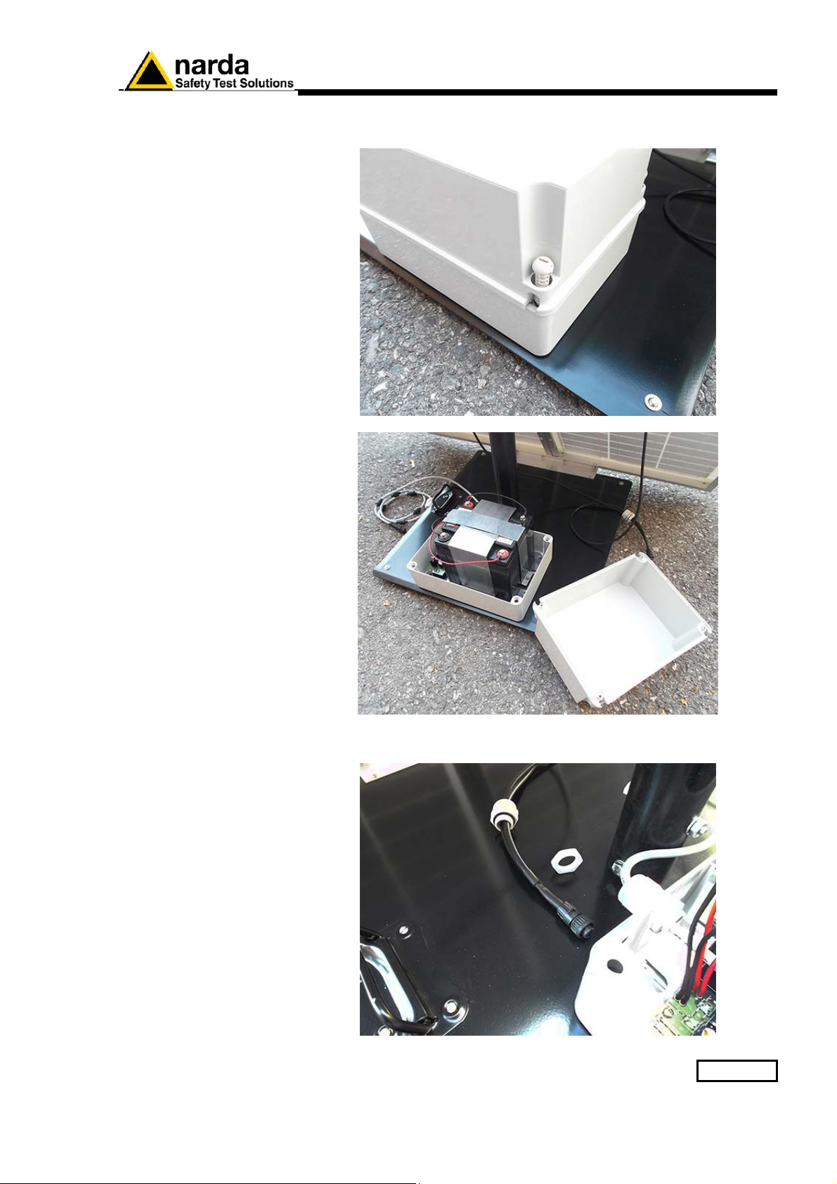
2.6.5.4 Solar panel wiring
and fuse
Remove the Power Pack cover
Remove the nut from the chock of the solar panel cable.
Installation and use 2-13
Page 32
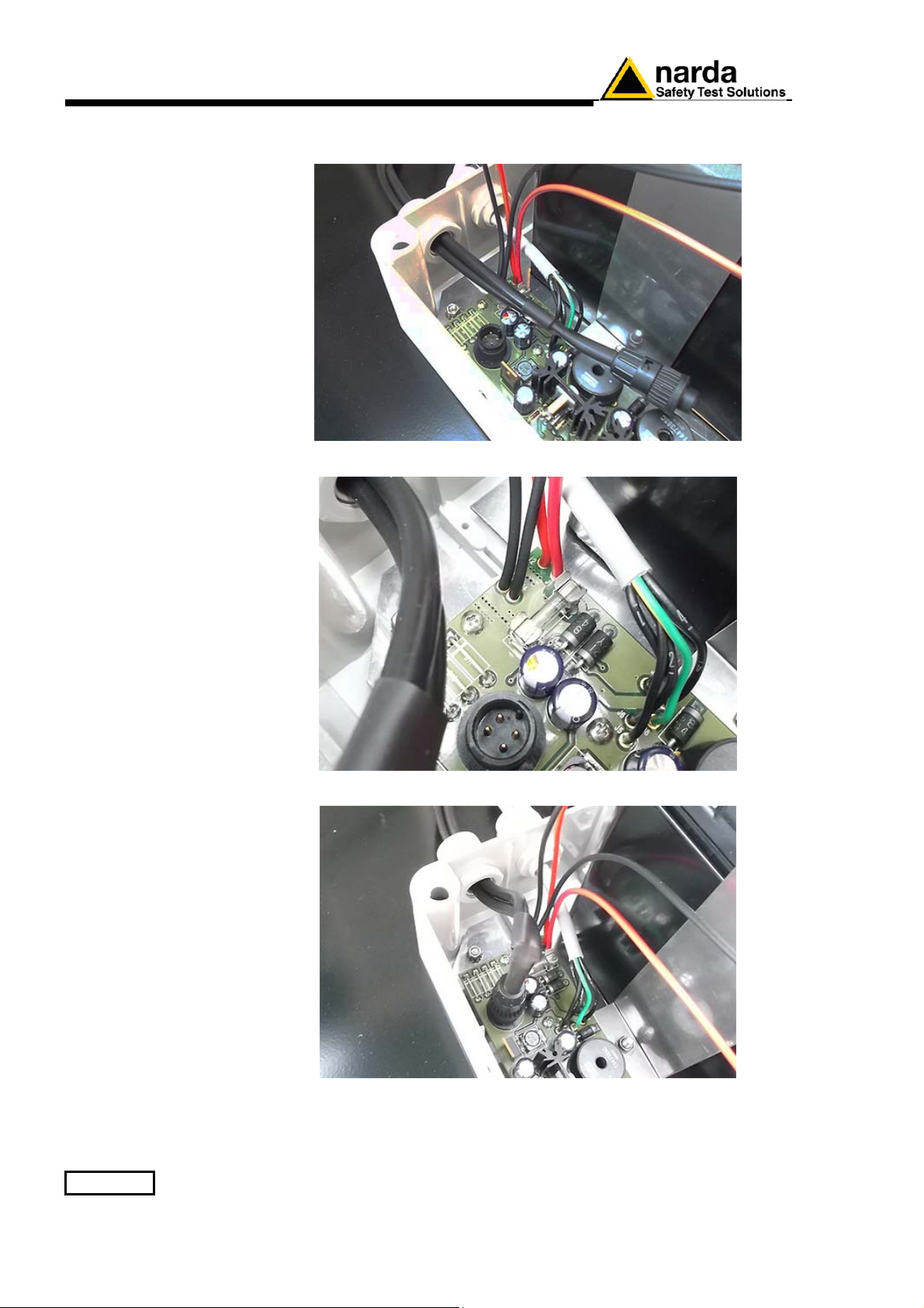
Thread the cable through the hole in the box and screw the nut to fasten
the chock to the Power Pack.
Place the fuse.
Plug the solar panel connector.
Close the Power Pack box
2-14 Installation and use
Page 33
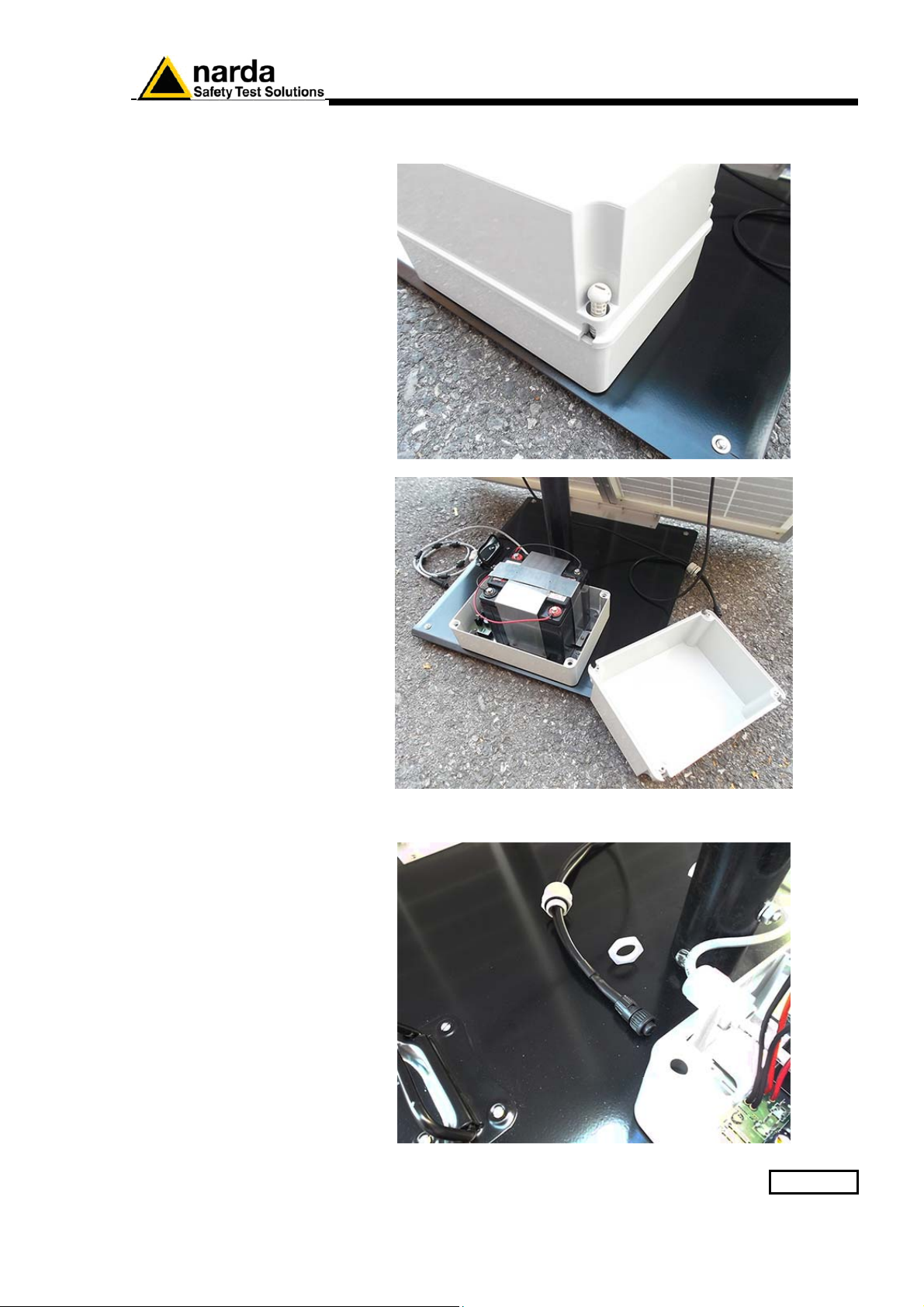
2.6.6 Battery pack
wiring and fuse
(AMS-8063-02 only)
Remove the Power Pack cover
Remove the nut from the chock of the power supply cable.
Installation and use 2-15
Page 34
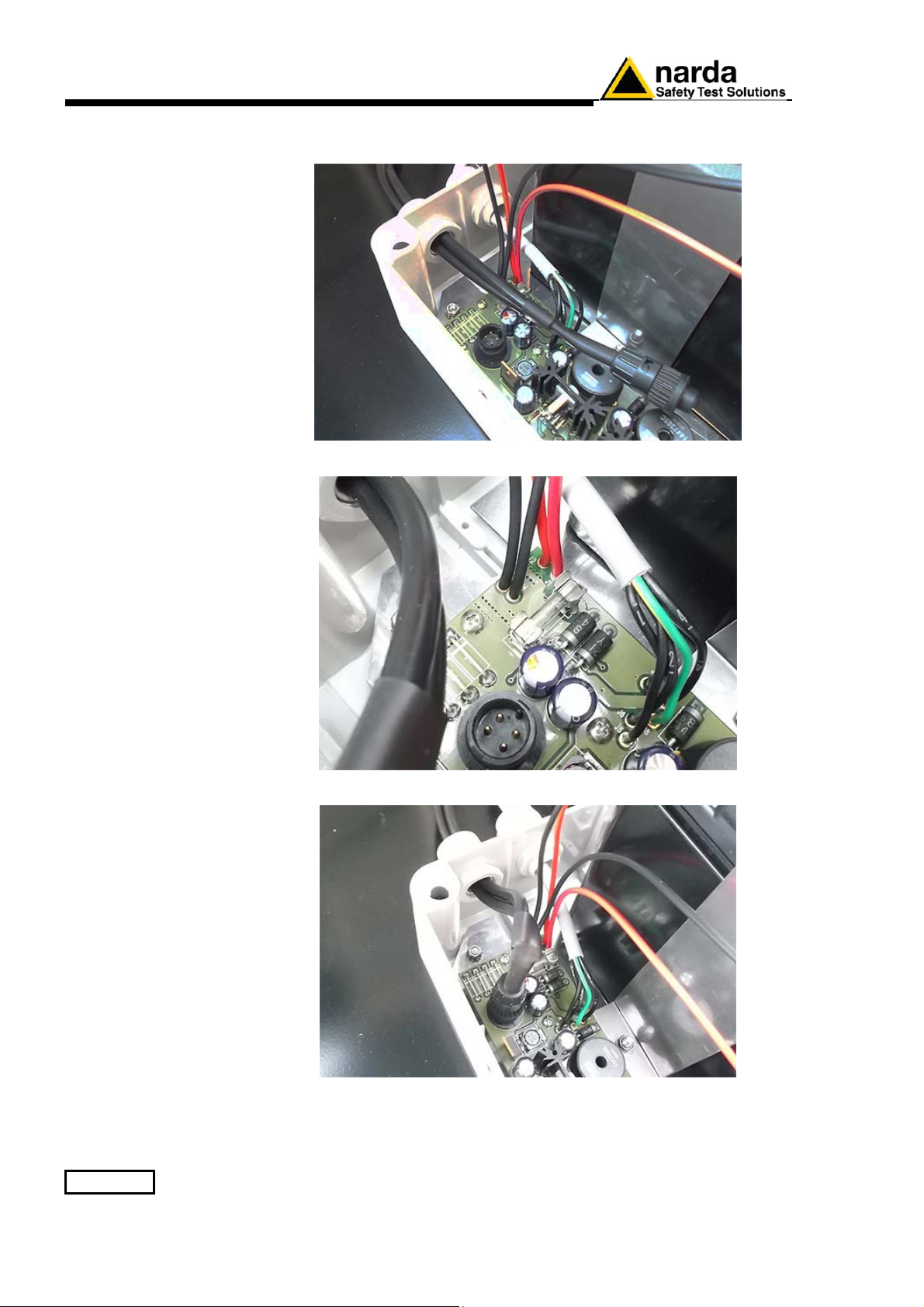
Thread the cable through the hole in the box and screw the nut to fasten
the chock to the Power Pack.
Place the fuse.
Plug the power supply connector.
Close the Power Pack box
2-16 Installation and use
Page 35
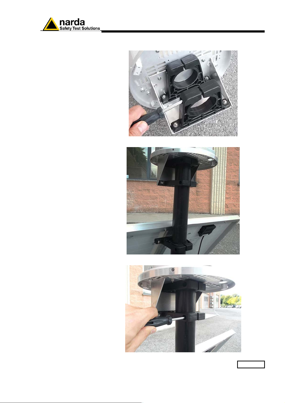
2.6.7 Baseplate
mounting
Before mounting the baseplate on the pole, unscrew the Pan head screw
inside the both PA6 black brackets without losing it completely.
Mount the receiver unit on the pole.
Fasten the unit by tightening the bracket screws.
Installation and use 2-17
Page 36
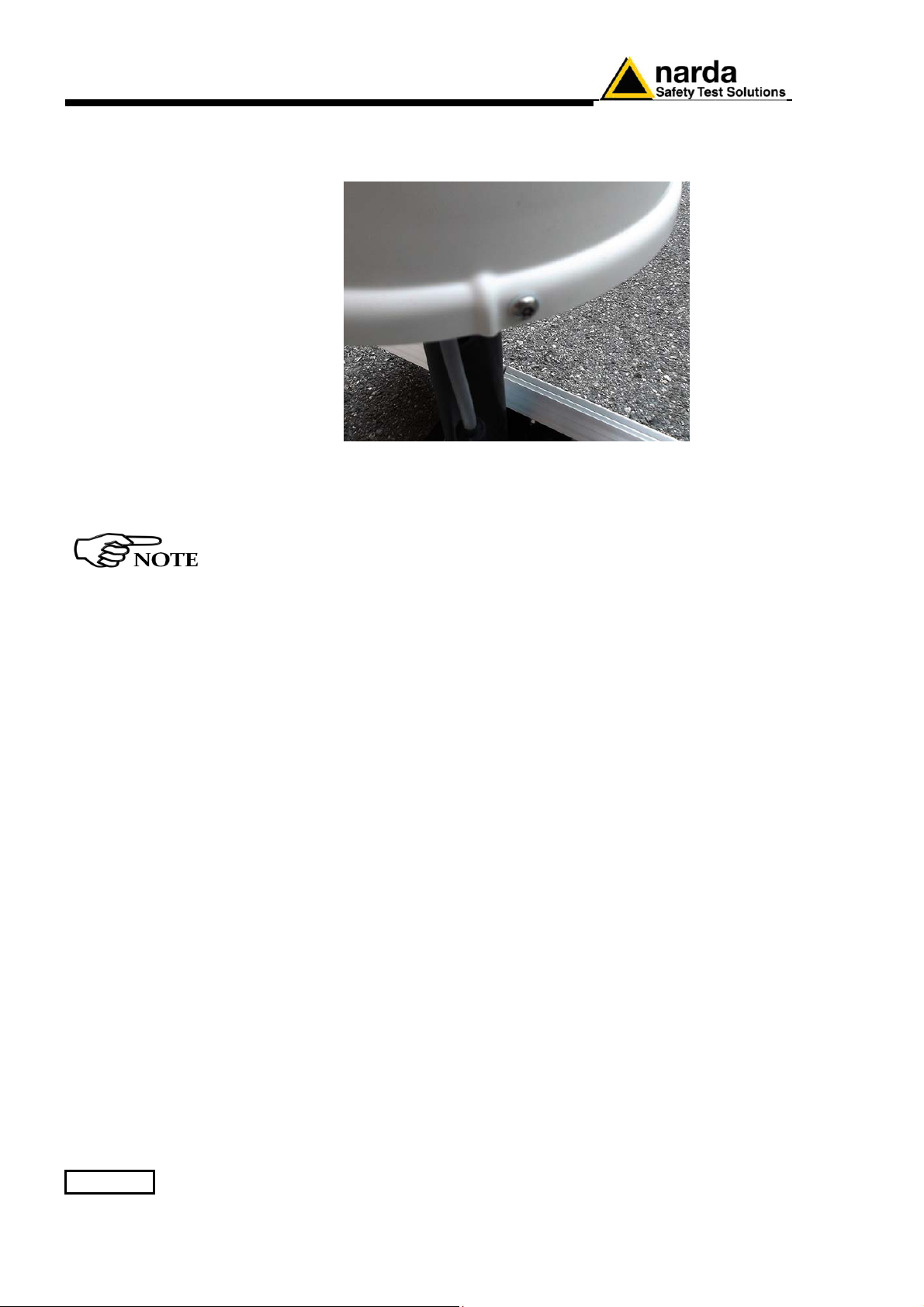
2.6.8 Radome opening
Remove the screws from the receiver baseplate to allow the Radome
removing.
Remove along its axis the protective case
Considering that it has been designed for outdoor use and the main
operations are generally performed remotely.
Controls and connections are available inside the protective case as
listed onward in this manual and can be reached by removing the
station Radome or the power pack cover.
2-18 Installation and use
Page 37
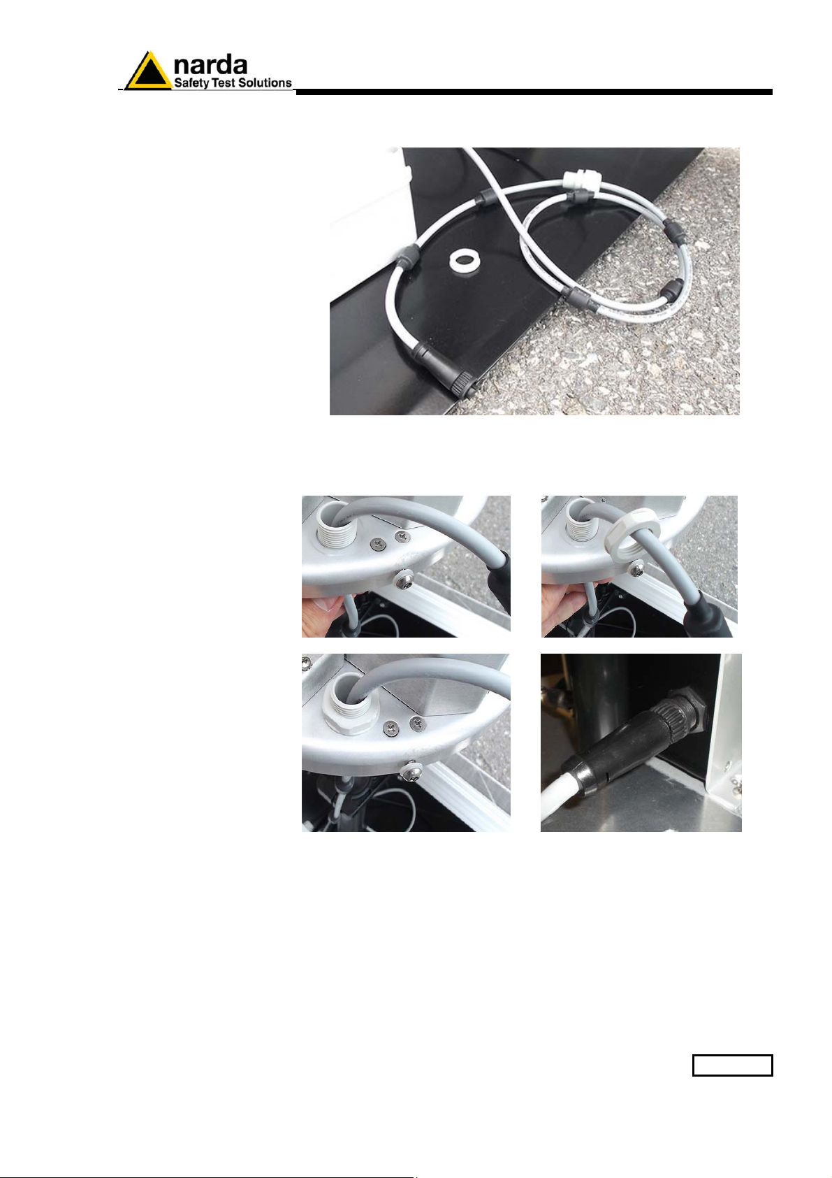
2.6.9 Battery pack power
cable
Remove the nut from the chock of the power cable.
Install the power cable by mounting the chock in the hole of the receiver
baseplate, plug the power supply connector to the Data/Power supply
box holding by the plastic part and check the status LEDs.
Installation and use 2-19
Page 38
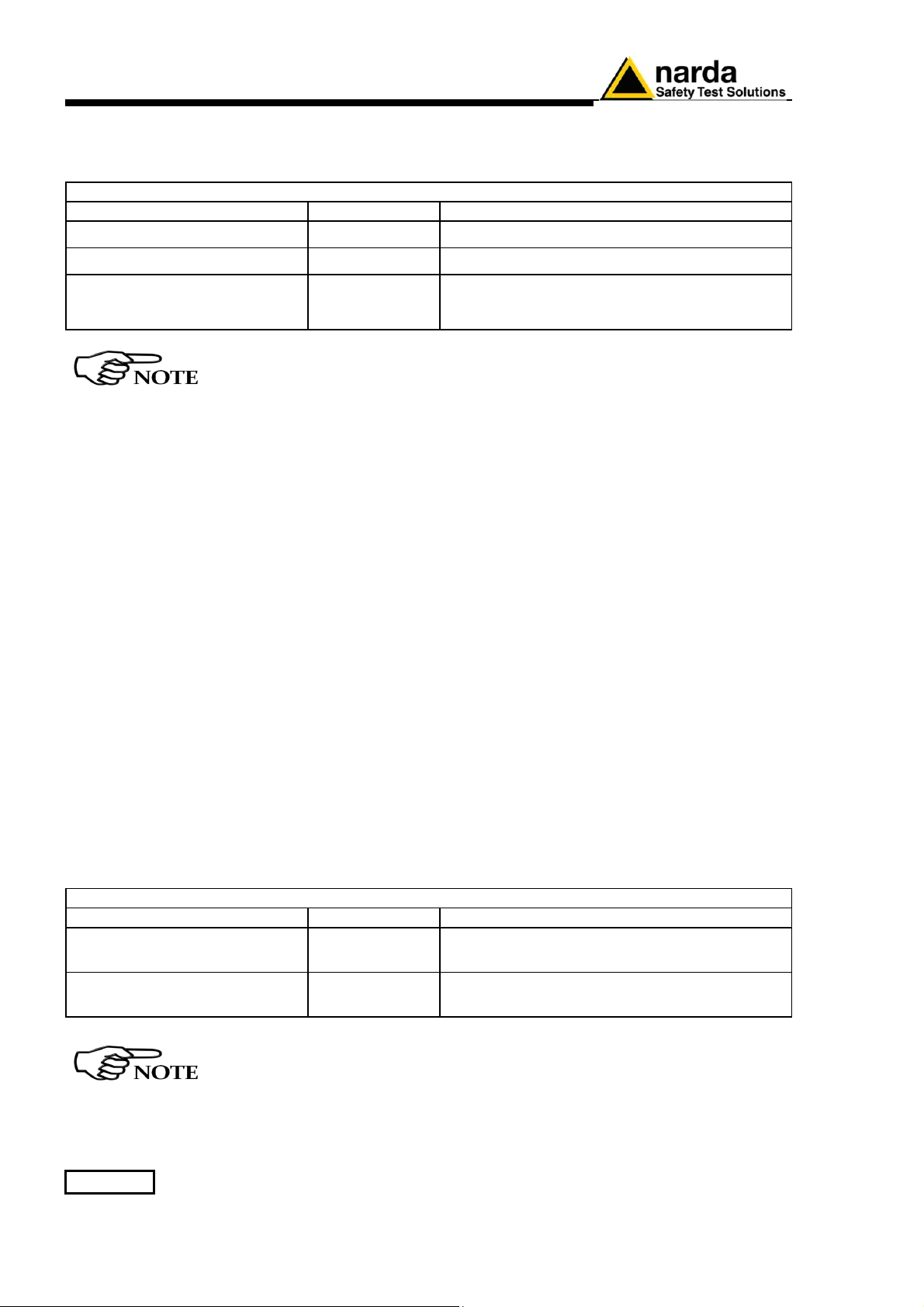
2.6.10 Led LEDs
8063-Shutter status
Both LEDs let the user know about the state of process as shown in the
following table.
Table 2-1 Led 8063-Shutter status
Led status LEDs Action
Steady Red EHP-8063 recharging battery
Steady Green EHP-8063 Battery recharging completed
Communication between PC and EHP-8063 in
off off
progress and correct.
(the battery is not charging)
If the communication with the PC is not successful, the EHP-8063 will
automatically be charged after about 3 minutes.
2.6.11 Led WiFi serial
converter status
(AMS-8063-00 only)
The LED let the user know about the state of the WiFi serial converter (for
further information see the User’s manual provided with the device).
2.6.12 Switch
Switch EHP-8063 on using the level switch
EHP-8063 on
2.6.13 Led EHP-8063
status
When switched on, the three-color ON DATA LED will provide the
following information:
After switching on the analyzer, the ORANGE LED lights up for about ½
second as an auto-check, after that the Green light starts blinking which
means that the firmware has been correctly downloaded.
Table 2-2 Led EHP-8063 status
Led status LEDs Action
Blinking Red
The EHP-8063 is switch on but the
communication with PC is disconnected.
Blinking Green
The EHP-8063 can be switched off manually by means of level switch.
When switch EHP-8063 on for the first time only, it is in charging
2-20 Installation and use
mode for 3 minutes and can not communicate with the PC.
The EHP-8063 is switch on and the
communication with PC in progress and correct.
Page 39
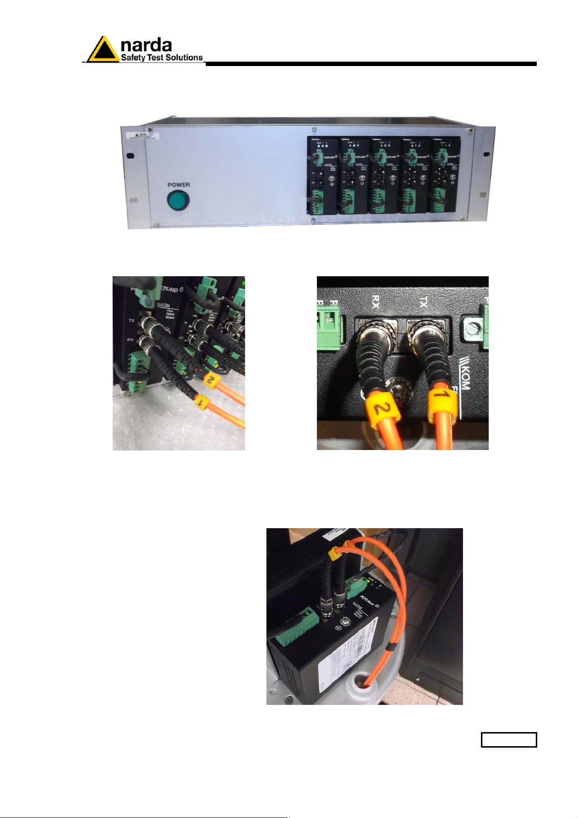
2.6.14 AMS-8063-02
Interface box
Switch AMS-8063-02 Interface box on using the green push-button on the
front panel.
Fiber optic on
AMS-8063-02 interface box side
Connect the Interface box to the AMS-8063-02 Area Monitor Station by
fiber optic paying attention to the correct correspondence in both side.
Fiber optic on
AMS-8063-02 Area Monitor side
Install the Fiber optic on the AMS-8063-02 Area Monitor station side by
mounting the chock in the hole of the receiver baseplate, plug the Fiber
optic to the Optical converter holding by the metallic part.
Installation and use 2-21
Page 40
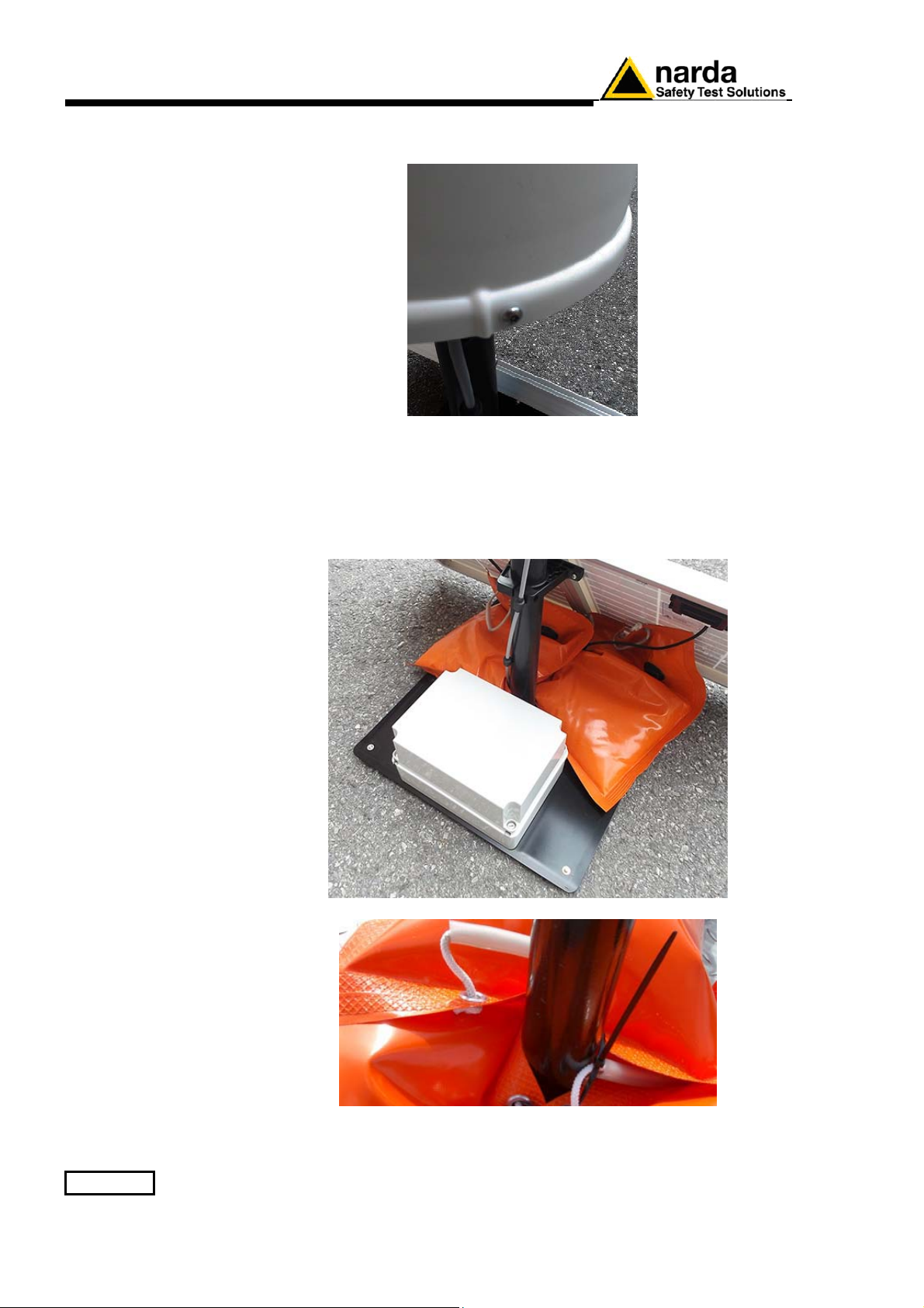
2.6.15 Radome
mounting
Insert along its axis the protective case and tight the four screws to fix the
Radome
2.6.16 Bags
The AMS-8063 is usually installed outdoors where atmospheric agents,
especially strong winds, can endanger its stability.
To ensure the necessary stability under the worst possible conditions, the
unit is supplied with three ballast bags that can be filled with water or sand
and fastened to the base of the mast.
Fasten the ballast bags to the mast using the plastic straps.
The AMS-8063 installation is completed.
2-22 Installation and use
Page 41
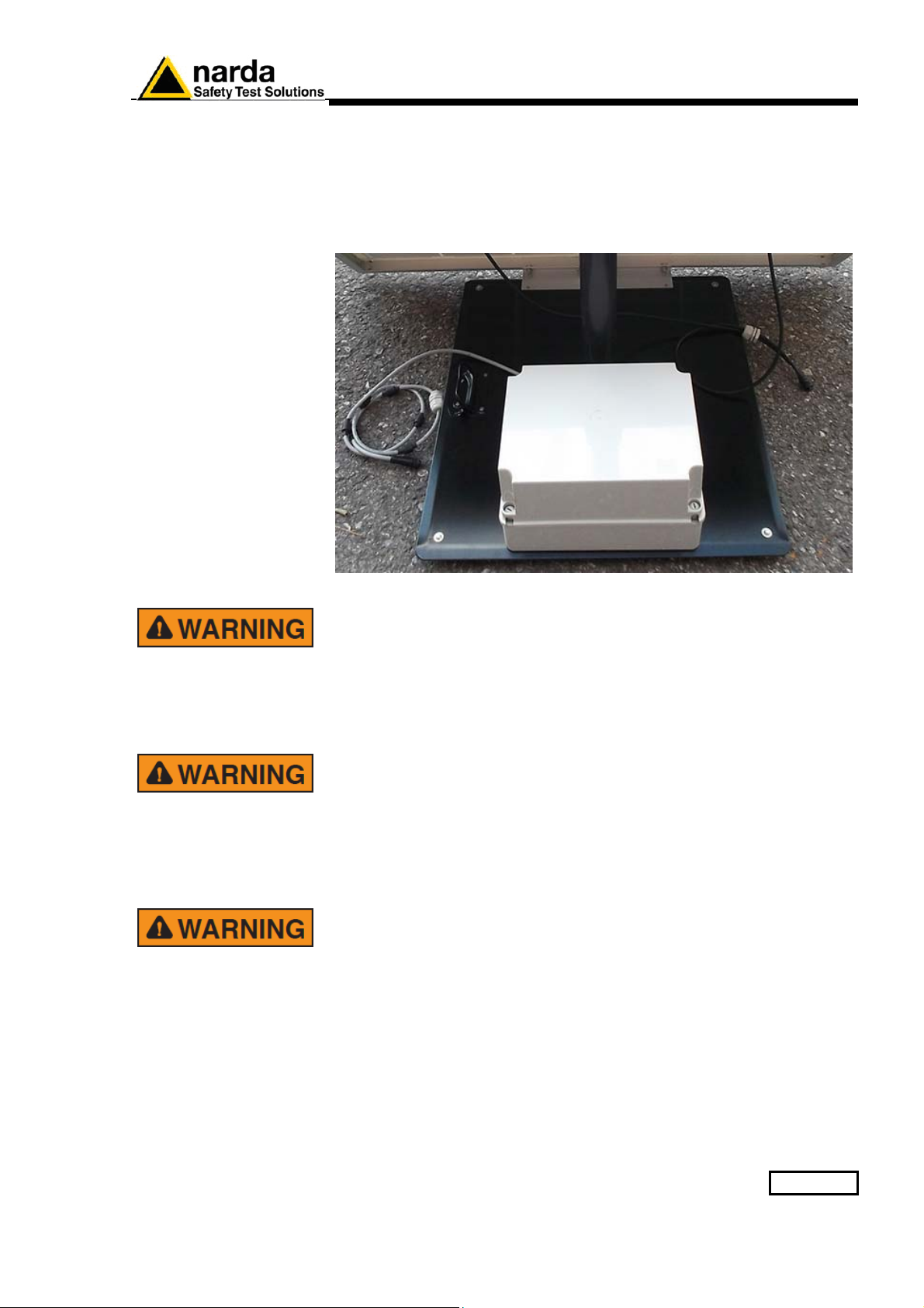
2.6.17 Battery charging
A complete battery charging should be completed before starting
measurements.
Lead batteries are located within the power pack on the support base and
automatically recharged by the solar panels (if connected) or by an
external power source.
AMS-8063 power system includes high quality lead batteries which
provide very good performance even in the voltage, current and
temperature most severe condition. Nevertheless, as happens in all
lead accumulators, capacity is influenced by temperature. Best
performance are achieved around 20°C.
The lead batteries with a nominal voltage of 12 V can be damaged if
left for a long period with voltage below 11,58 V.
Below this value chemical processes that could damage them begin.
The AMS-8063 batteries apply a technology to reduce this
phenomenon.
Furthermore the supply circuit disconnect the load (switching the
unit off) when the battery voltage is low.
Anyway, if not used, the station should be switched off.
Battery should be recharged if the station has not to be used for a
long period.
Any part of the instrument can only be replaced by NARDA, therefore,
in case of damage to parts and/or malfunctions, contact the NARDA
service center.
Installation and use 2-23
Page 42
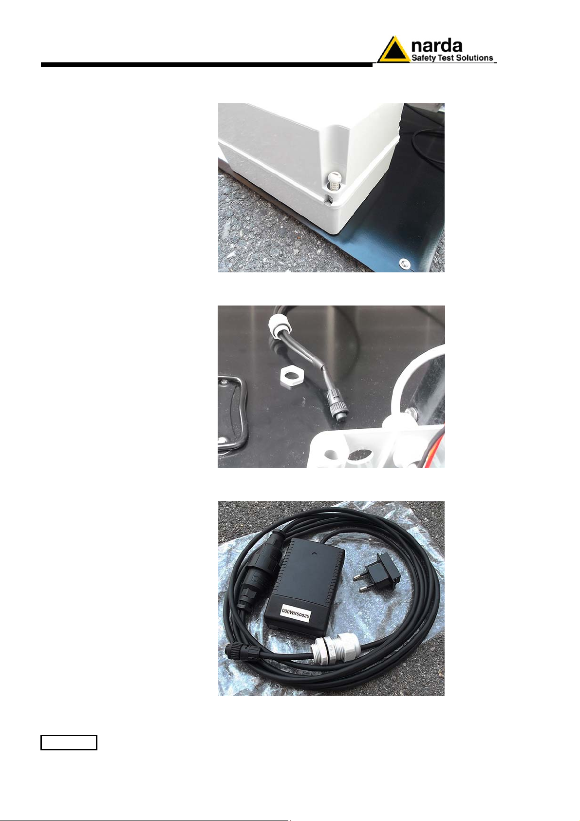
Remove the Power Pack cover.
Disconnect the solar panel from the Power Pack removing the chock.
Connect the provided power supply/battery charger for a complete charge.
2-24 Installation and use
Page 43
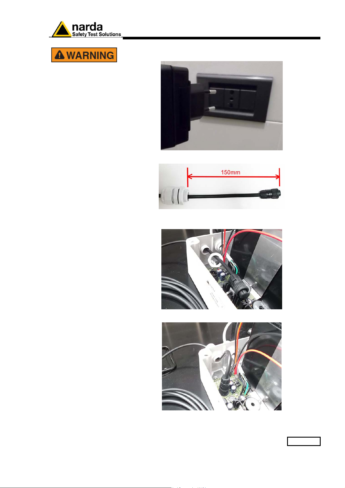
Plug the battery charger with the proper adapter to the mains outlet
before connect the multipole connector to the Power pack.
Fasten the cable to the strain relief.
Thread the cable through the hole in the box and screw the nut to fasten
the chock to the Power Pack.
Plug the multipole battery charger connector to the Power pack.
Close the Power Pack cover
Installation and use 2-25
Page 44
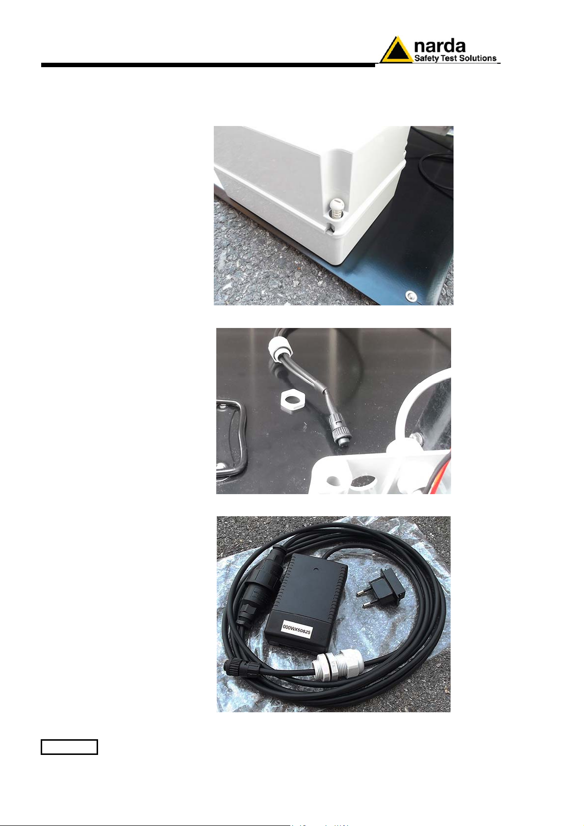
2.6.18 External power
supply
Execute the following wiring in the case an external power supply is
requested during measurements.
Remove the Power Pack cover.
Disconnect the solar panel from the Power Pack removing the chock
Connect the provided power supply/battery charger.
2-26 Installation and use
Page 45
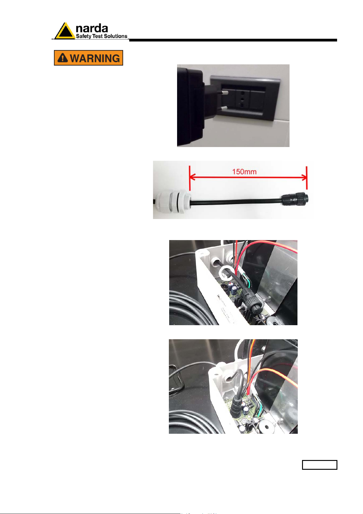
Plug the battery charger with the proper adapter to the mains outlet
before connect the multipole connector to the Power pack.
Fasten the cable to the strain relief.
Thread the cable through the hole in the box and screw the nut to fasten
the chock to the Power Pack.
Plug the multipole power supply connector to the Power pack
Close the Power Pack cover
Installation and use 2-27
Page 46
2.7 AMS-8063-00
Operating principle
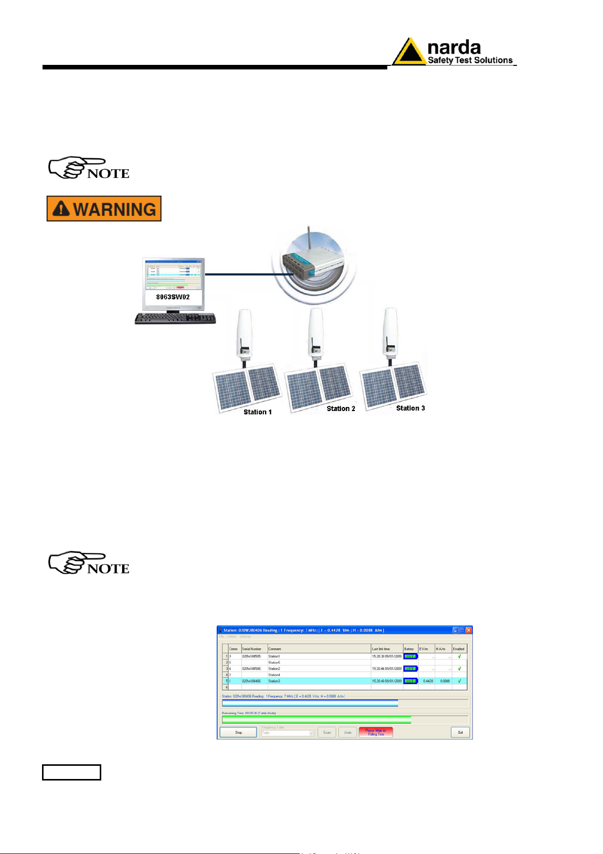
The Wi-Fi Serial Converter changes the AMS-8063 into Wi-Fi device
through a RS-232 serial port on DB9 connector.
The PC handles the AMS-8063 through the access point (AP) that allows
the connection to a WLAN network.
The Wi-Fi Serial Converter is supplied by the 8063-Shutter through the
appropriate pin on terminal block.
For further information see the User’s Manual provided with the Wi-Fi
device.
Whenever possible, it is a good rule to install the unit at some
distance from walls, buildings and other obstacles that could affect
the field measuring and the wireless signals reaching the WiFi device
In this configuration the PC performs a continued and cyclical check of the
three stations (Station1, Station2 e Station3): the station queried measures
the electric and/or magnetic field value for each frequency stored in the
Frequency Table (the battery is not charged to not affect the field value
and both 8063-Shutter LEDs are switched off).
If the station’s battery runs out, it will be charged automatically (the 8063Shutter red led switches on); when the battery recharging is completed the
green led is on.
If a station is not connected or the communication is not established, the
EHP-8063 will be automatically in charging mode.
The EHP-8063 can be switched off manually by means of level switch.
When switch EHP-8063 on for the first time only, it is in charging
mode for 3 minutes and can not communicate with the PC.
The connection is reestablished when the battery voltage will be above 3,05 V.
The PC handles the AMS-8063 through the 8063SW02 software.
2-28 Installation and use
Page 47
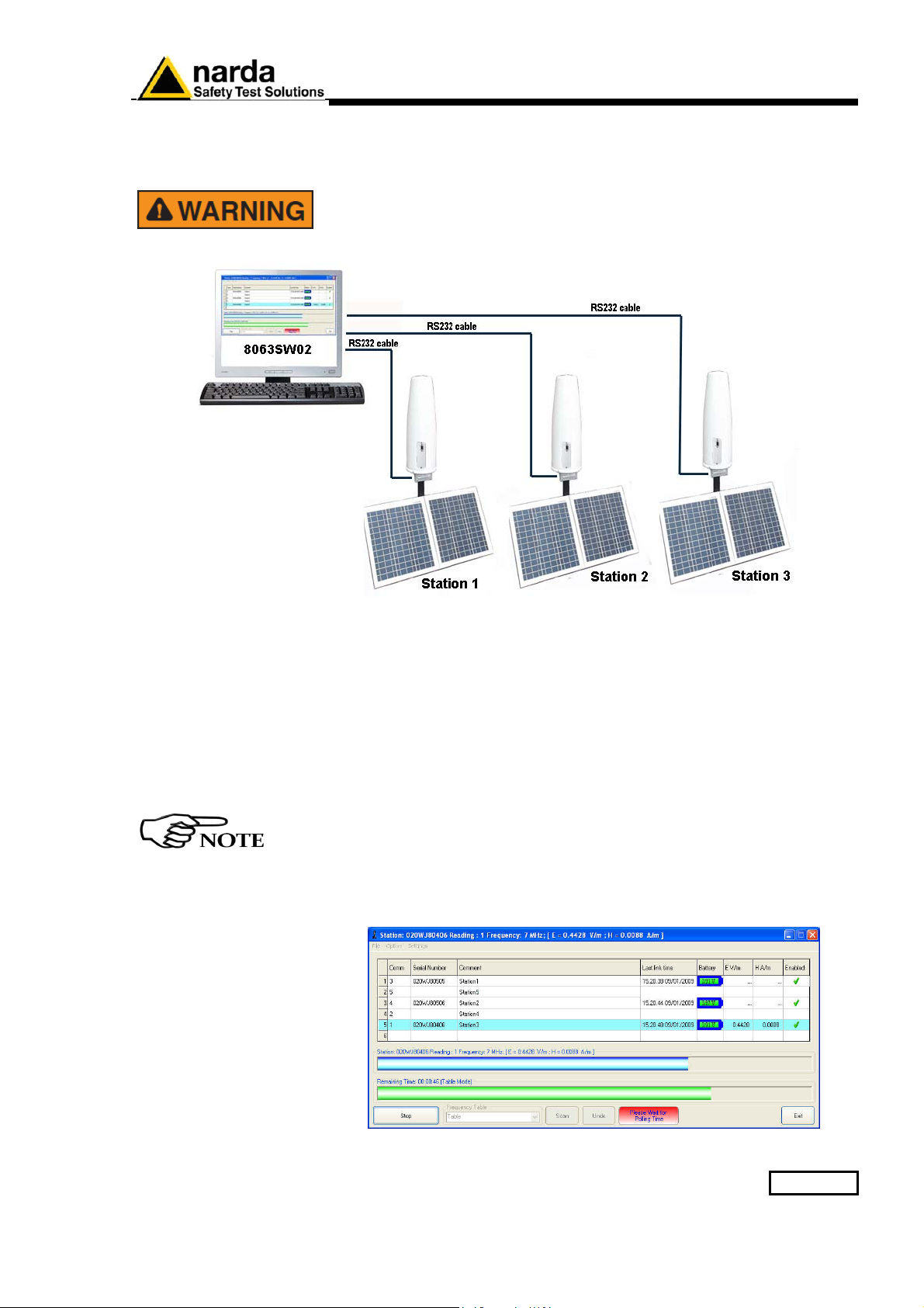
2.8 AMS-8063-01
Operating principle
The 8063-Shutter changes the AMS-8063 into RS-232 device through a
RS-232 serial port on DB9 connector.
The PC handles the AMS-8063 through the RS232 cable.
Whenever possible, it is a good rule to install the unit at some
distance from walls, buildings and other obstacles that could affect
the field measuring.
In this configuration the PC performs a continued and cyclical check of the
three stations (Station1, Station2 e Station3): the station queried measures
the electric and/or magnetic field value for each frequency stored in the
Frequency Table (the battery is not charged to not affect the field value
and both LEDs 8063-Shutter are switched off).
If the station’s battery runs out, it will be charged automatically (the 8063Shutter red led switches on); when the battery recharging is completed the
green led is on.
If a station is not connected or the communication is not established, the
EHP-8063 will be automatically in charging mode.
The EHP-8063 can be switched off manually by means of level switch.
When switch EHP-8063 on for the first time only, it is in charging
mode for 3 minutes and can not communicate with the PC.
The connection is reestablished when the battery voltage will be above 3,05 V.
The PC handles the AMS-8063 through the 8063SW02 software.
Installation and use 2-29
Page 48
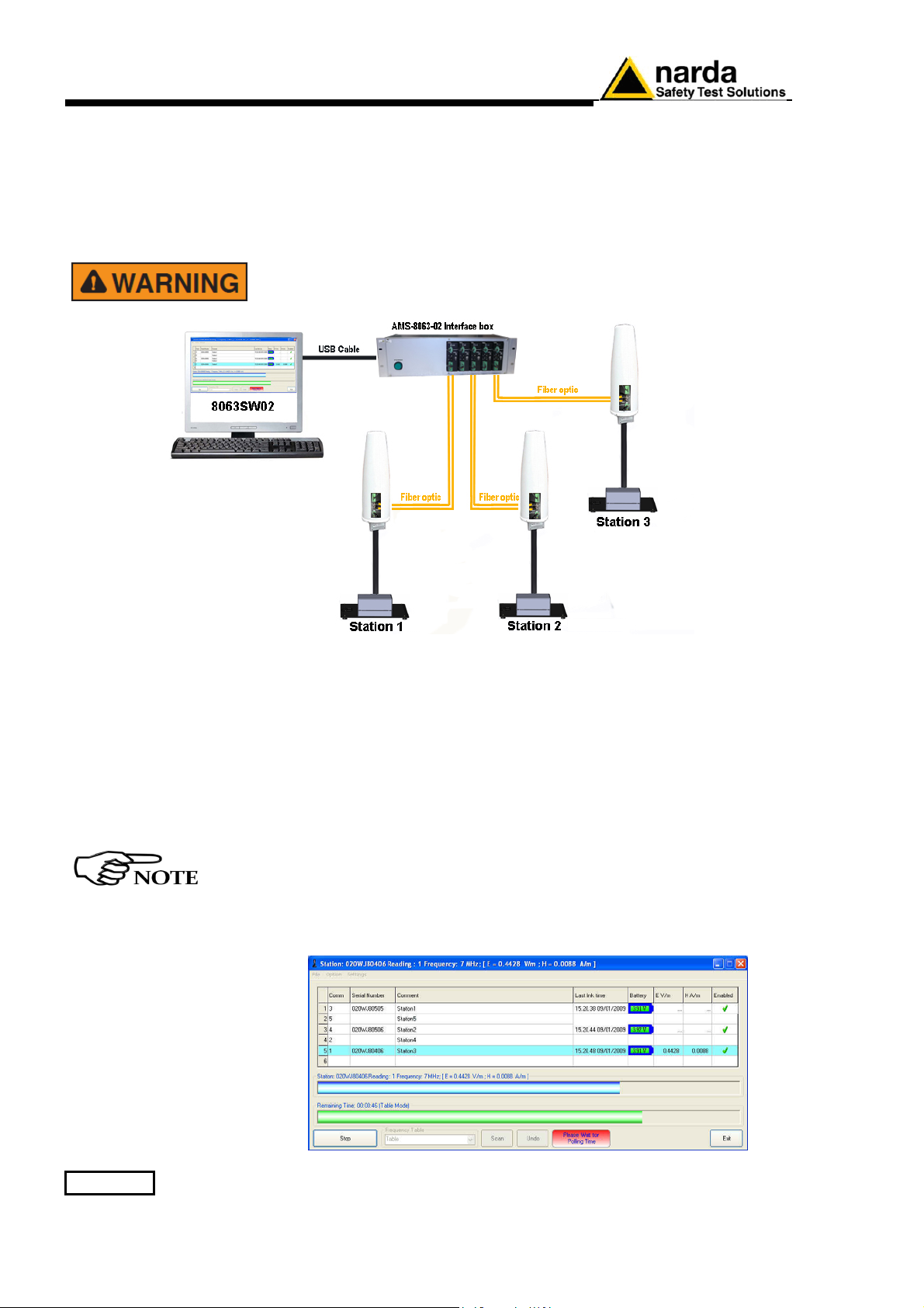
2.9 AMS-8063-02
Operating principle
The Optical Serial converter changes the AMS-8063 into optic device
through an optic link port; it is supplied by the 8063-Shutter through the
appropriate pin on terminal block.
The PC handles the AMS-8063 through the AMS-8063-02 Interface box
that allows a long optical connection.
The AMS-8063-02 Interface box is connected to PC by USB cable.
Whenever possible, it is a good rule to install the unit at some
distance from walls, buildings and other obstacles that could affect
the field measuring.
In this configuration the PC performs a continued and cyclical check of the
three stations (Station1, Station2 e Station3): the station queried measures
the electric and/or magnetic field value for each frequency stored in the
Frequency Table (the battery is not charged to not affect the field value
and both LEDs 8063-Shutter are switched off).
If the station’s battery runs out, it will be charged automatically (the 8063Shutter red led switches on); when the battery recharging is completed the
green led is on.
If a station is not connected or the communication is not established, the
EHP-8063 will be automatically in charging mode.
The EHP-8063 can be switched off manually by means of level switch.
When switch EHP-8063 on for the first time only, it is in charging
mode for 3 minutes and can not communicate with the PC.
The connection is reestablished when the battery voltage will be above 3,05 V.
The PC handles the AMS-8063 through the 8063SW02 software.
2-30 Installation and use
Page 49
3 – 8063SW02 - User’s Guide
3.1 Introduction
3.2 Hardware
requirements
1
This Chapter provides a guide for the installation and use of the data
acquisition and control software 8063SW02.
It also explains the functions available and the configuration details.
The 8063SW02 software is a control program fully integrated into the AMS8063 Area Monitor System.
The 8063SW02 software features the following basic functions:
- Changing measurement and storing settings;
- Querying and monitoring all the AMS-8063 installed and enabled;
- Acquisition and display of electric and/or magnetic field values on the PC;
- Downloading data with automatic generation of graph (.JPG or .BMP) and
table (.TXT) to be used for easy data exchange with any “Office”
applications;
- Controlling and verifying the reliability of the data recorded.
To ensure the proper operations of the 8063SW02 software, the minimum
hardware requirements of the Personal Computer are:
• Pentium processor;
• at least 16 Mb RAM;
• at least 100 Mb of free space on your hard disk;
• Free USB, RS232, Ethernet port;
• Operating System: Windows™ XP, Vista, Win7, Win10
For proper installation of the Access Point WiFi refer to the instructions of
manufacturer.
To obtain software updates, please contact your NARDA distributor
or download it directly from the NARDA Web site: www.narda-sts.it .
The User might have the need of administrator privileges to install
and run the software in Windows 7 or Windows 10; for further
information see § 3.4 and § 3.8 .
Document AMS8063EN-71005-1.22 - © NARDA 2017
8063SW02 - User’s Guide 3-1
Page 50

3.3 Use of the Software
8063SW02
The procedure for the correct use of the AMS-8063 system is the following
• Make sure the PC meets the minimum hardware requirements;
• Install the software on the PC;
• If needed, install the USB-RS232 adapter (optional) on the PC;
• Set the 8063SW02 COM port settings;
• Set the AMS-8063 Delay command setting;
• Double click on the 8063SW02 icon to run the software;
• If needed, modify appearance of the program with Option/Aspect
function;
• Make a list of all AMS-8063 installed and save with Save Panels
function (File/Save Panels); otherwise load a previous system with
Open Panels command (File/Open Panels).
• Change measurement and storing settings with Settings/Measure
function.
• On the “Enabled” column of the control panel, tick √ the station to be
queried;
• Query the station with the function:
- SCAN: requests instantaneous field value (single query – not
continued);
- EXECUTE: Requests instantaneous field value (cyclical and
continued);
• Acquisition and display of the data recorded (chapter 4);
• Controlling and verifying the reliability of the data recorded.
3-2 8063SW02 - User’s Guide
Page 51
3.4 Software
installation
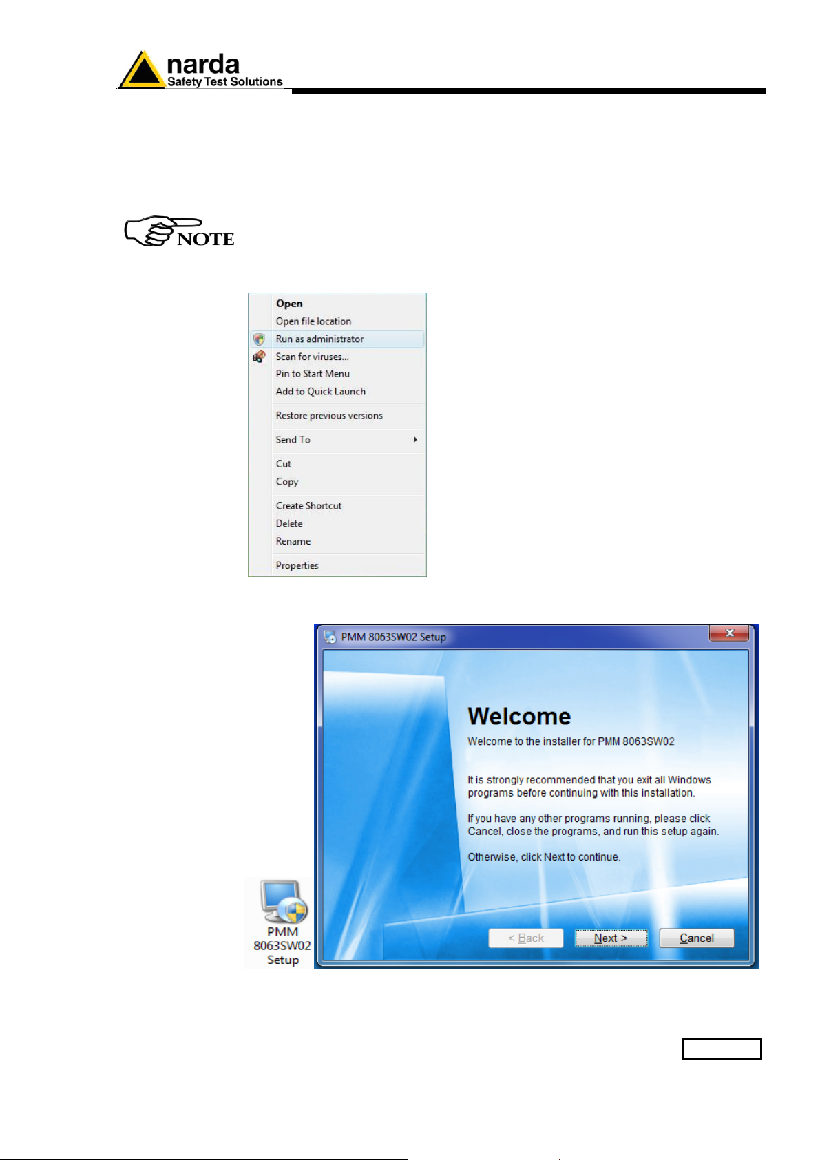
To install the 8063SW02 on PC from the supplied Software Media proceed as
follows:
In Computer Resources, browse the Software Media supplied.
The User must have administrator privileges to install the 8063SW02 software
in Windows 7 or Windows 10; right click on the program .exe file and click on
“Run as administrator” to temporarily run the program or application as an
administrator until close it (Windows 7 also allows to mark an application so
that it always runs with administrator rights).
To start the installation double click on the PMM 8063SW02 Setup icon.
8063SW02 - User’s Guide 3-3
Page 52
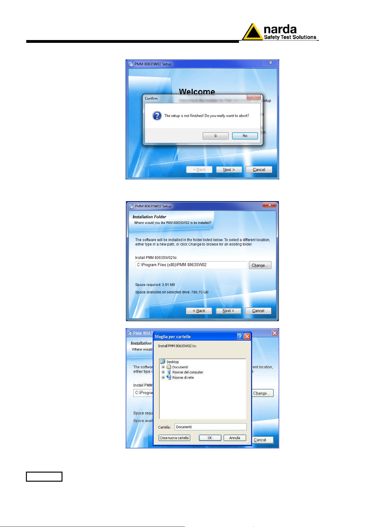
The installation can be aborted by clicking on Cancel.
The installation folder must be specified. Click Next to confirm the default folder
(recommended) or Change to modify.
3-4 8063SW02 - User’s Guide
Page 53
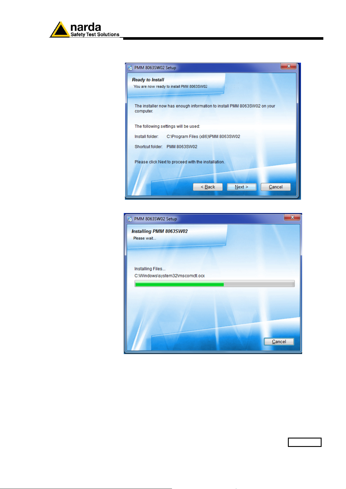
The installation folder must be specified. Click Next to confirm the default folder
(recommended) or Change to modify.
The installing status is displayed then.
8063SW02 - User’s Guide 3-5
Page 54
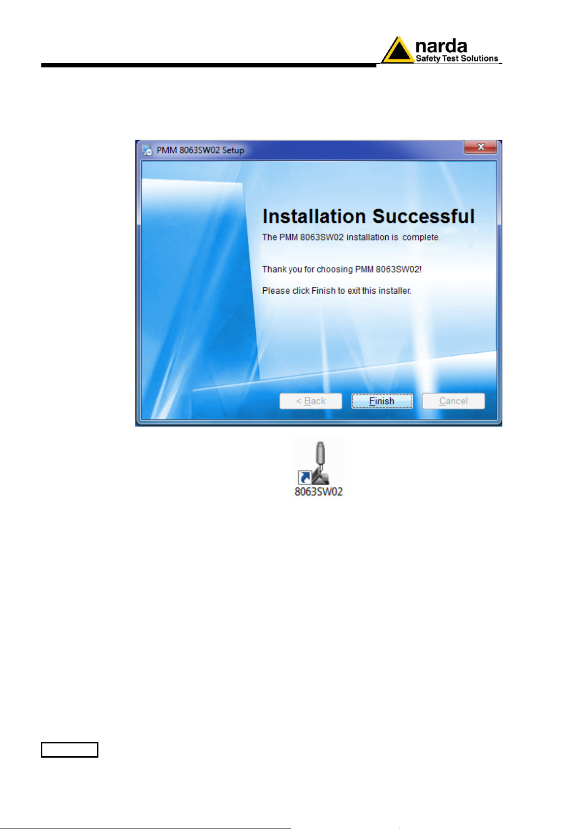
Click Finish to complete and exit the installer.
The folder PMM 8063SW02 is created under All Programs with the icon
8063SW02 on desktop
3-6 8063SW02 - User’s Guide
Page 55
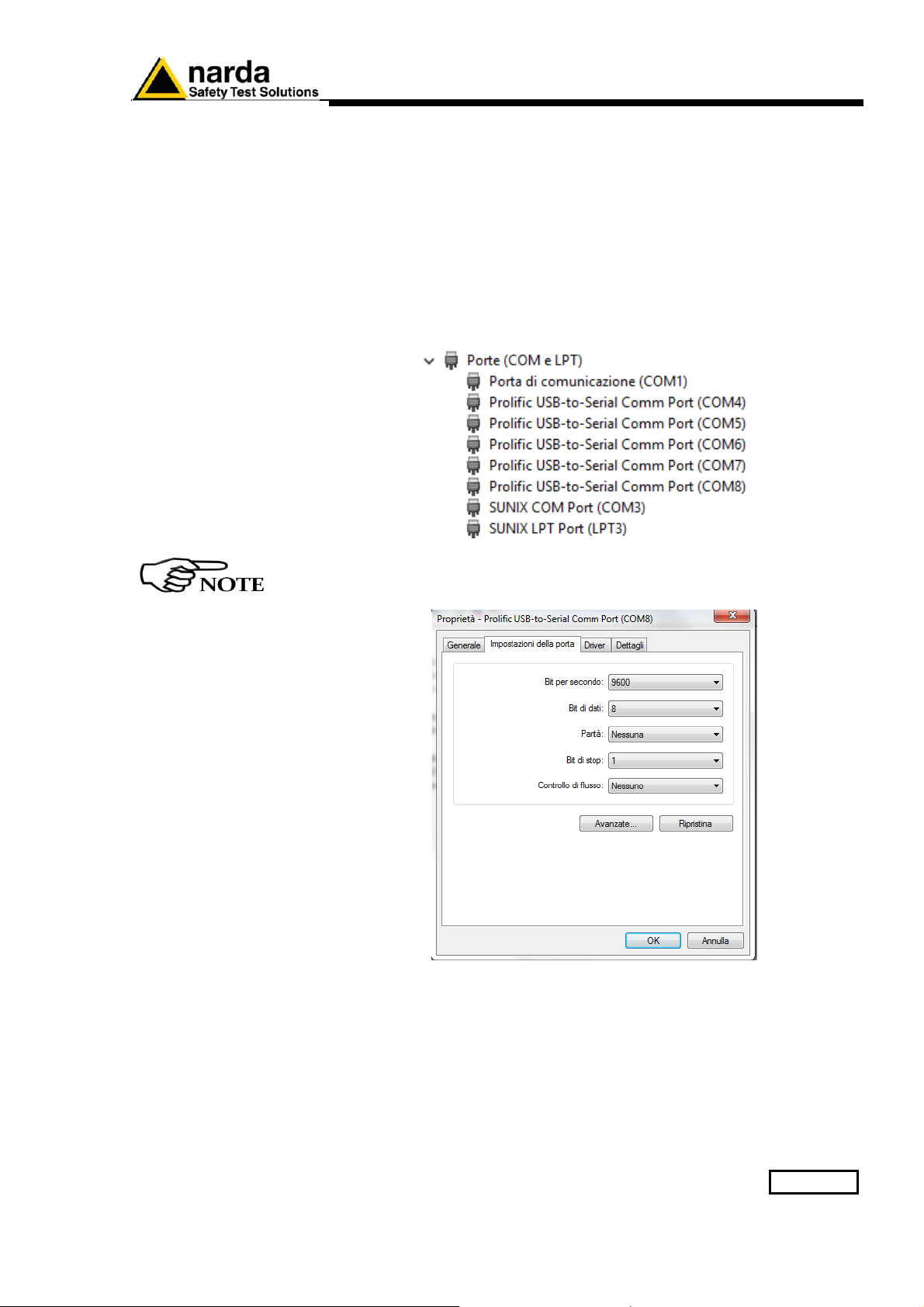
3.5 USB-RS232 Adapter
(optional, AMS-8063-01)
or AMS-8063-02 (Interface
box)
Connect the USB-RS232 adapter for AMS-8063-01 or the AMS-8063-02
Interface box to the PC by USB cable and wait for the “new hardware
installation” procedure. Drivers supplied with the adapter can be used as
well.
Enter in Peripheral management (Start > Control Panel > System and
Security > System > Device Manager).
The assigned COM can be found in Ports (COM & LPT) – Prolific USB-
to-Serial Comm Port (COMx).
COMx shows the COM port assigned to the USB-RS232 adapter or
Interface box.
To change the COMx port, double click the line Ports (COM & LPT) and
Prolific USB-to-Serial Comm Port (COMx). Enter in Port settings and
Advanced.
8063SW02 - User’s Guide 3-7
Page 56
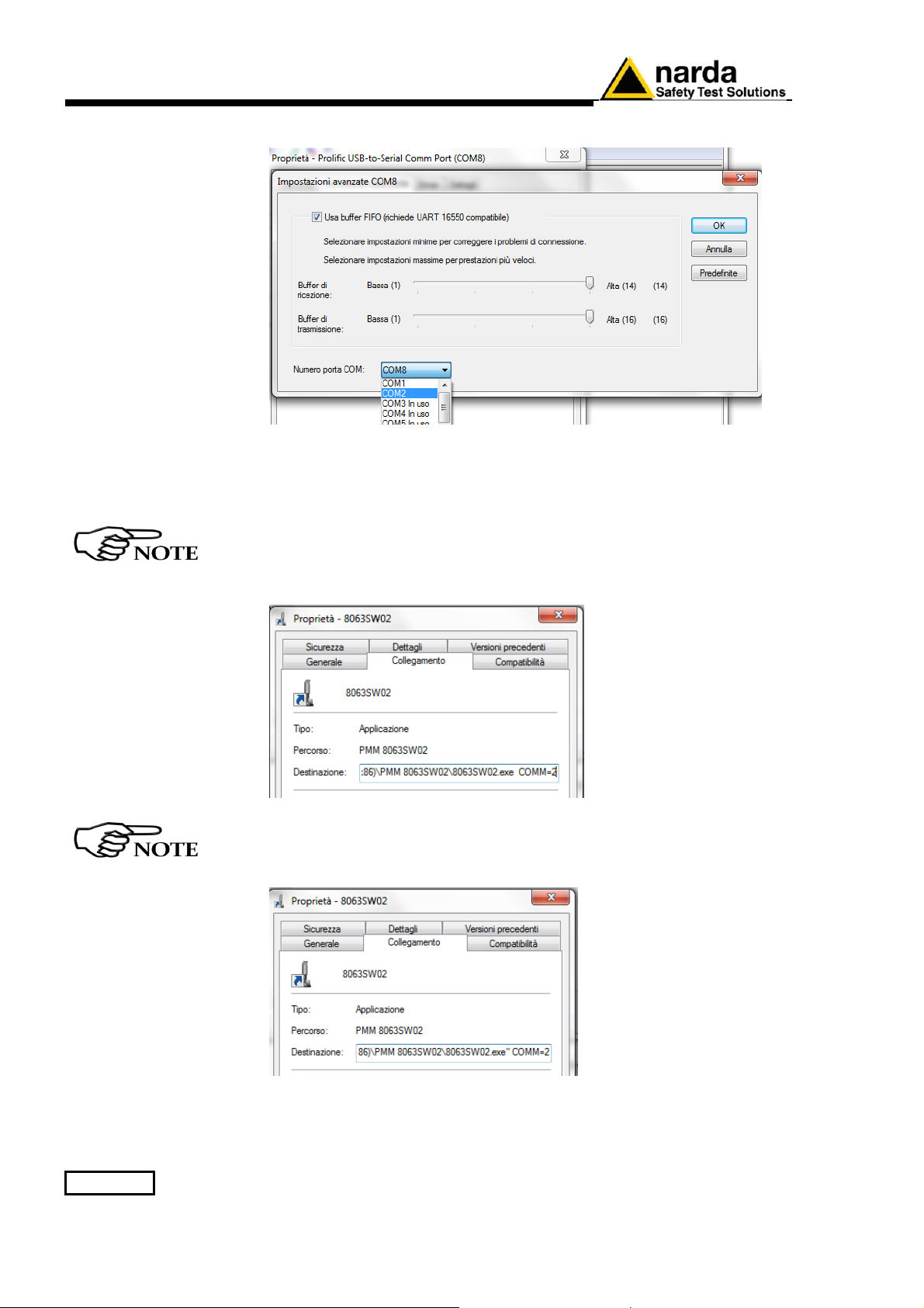
In Advanced Settings select the first COM port available; click OK
3.6 8063SW02
COM port settings
Select the icon 8063SW02 with the right mouse button
Select Properties;
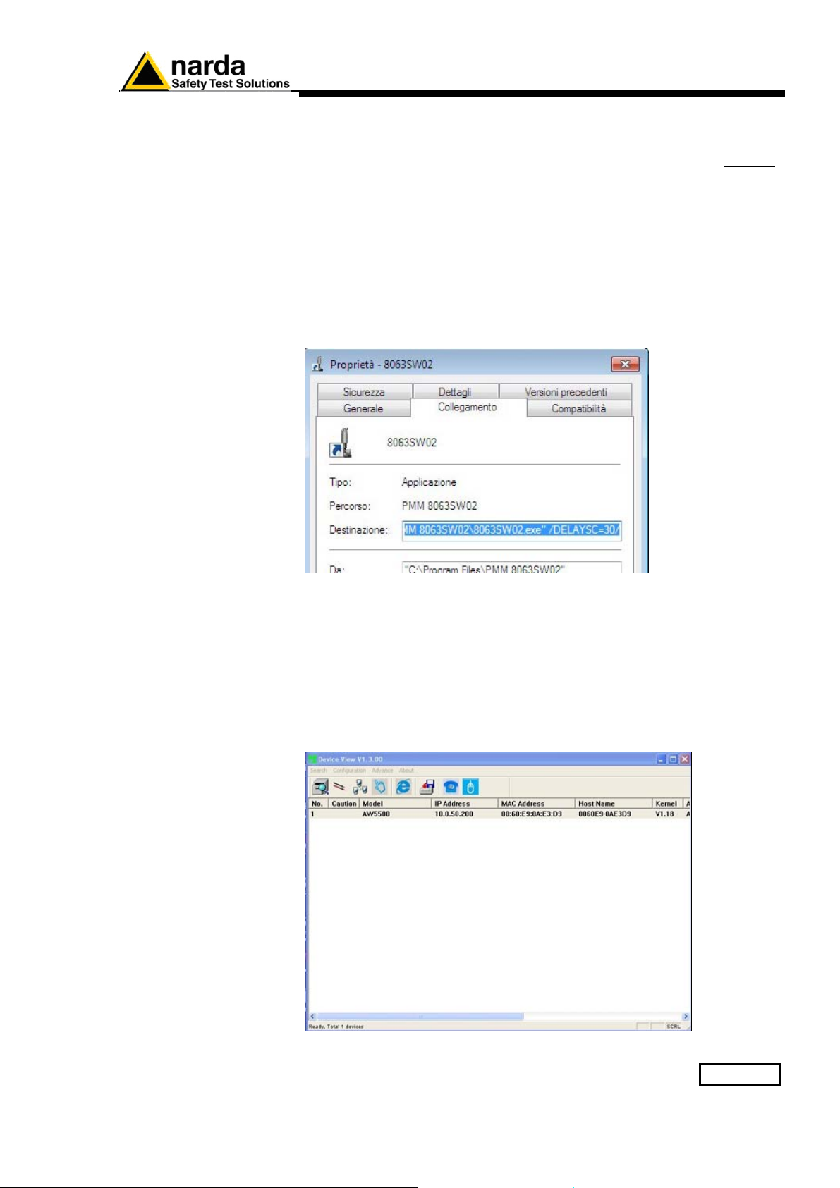
Add the command COMM=N preceded by a space (in capital letters) at the
end of the Destination field where N indicates the serial port to be used;
for example, if the Modem is connected to port 2, add the command
COMM=2.
In some operating system the Destination field is enclosed in double
quotation marks (“); in this case, the command COMM=N, preceded
by a space must be outside as in the example below.
Then confirm by selecting Apply and OK.
3-8 8063SW02 - User’s Guide
Page 57
3.7 AMS-8063 delay
Command setting
The software allows to query continuously and cyclically a system of AMS8063 monitoring stations (
§ 3.9.8 EXECUTE);
To set the querying delay time among AMS-8063 installed and enabled
proceed as follows:
Select the icon 8063SW02 with the right mouse button
Select Properties;
Add the command /DELAYSC=N/ preceded by a space (in capital letters)
at the end of the Destination field.
N indicates the delay time in seconds (the assigned value must be from 1
to 360); it is suggested a value equal or more than 30 seconds.
3.8 ATOP AW5500
Access point
installation
(AMS-8063-00 only)
Then confirm by selecting Apply and OK.
Connect the Access Point to the PC by ethernet cable.
Disable the firewall on the PC
Insert the software CD-ROM (provided with the Access Point) into the drive
and open the Device view software on the folder D:\Managment Utility; it
allows to set the Access Point; do not change the default settings.
8063SW02 - User’s Guide 3-9
Page 58
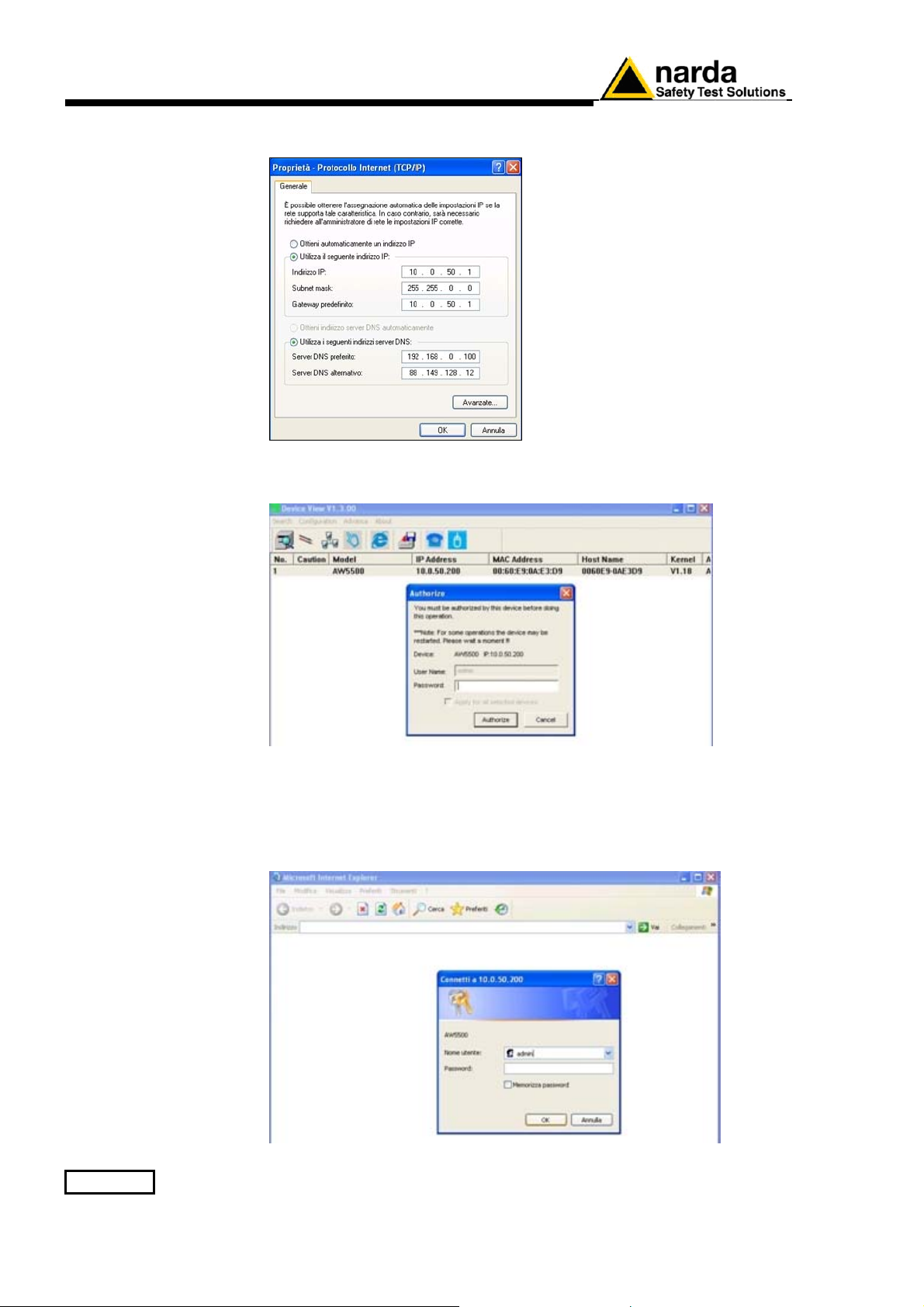
Set the IP address on the PC as shown below and confirm with OK:
Once again, open the settings Access Point window and click Row 1 twice.
The Password field must be left empty; click on Authorize
On the web browser, enter the IP address of the device on the URL
(http://10.0.50.200).
The authentication screen as shown in figure below; the default user name
is admin and password must be left empty.
Click on OK to confirm.
3-10 8063SW02 - User’s Guide
Page 59
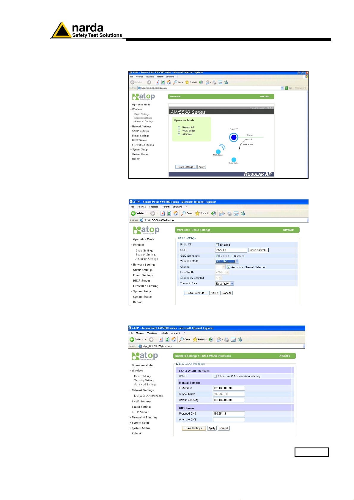
Once the user logins, the overview screen appear as shown in figure
below. Select Regular AP and click on Save Settings and Apply to go to
the next step.
Set the Basic settings as shown in figure below. Click on Save Settings
and Apply to go to the next step.
Set the LAN&WLAN Interface settings as shown in figure below. Click on
Save Settings and Apply to go to the next step.
8063SW02 - User’s Guide 3-11
Page 60
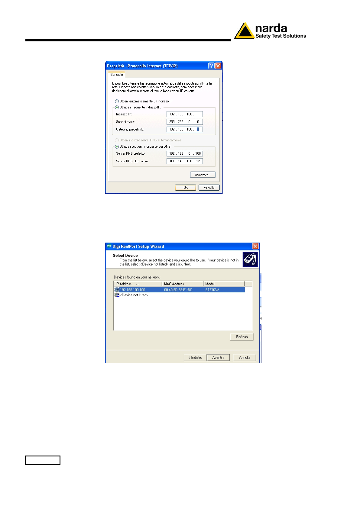
3.9 STE02W
Set the IP address on the PC as shown below and confirm with OK:
WiFi Serial Converter
installation
(AMS-8063-00 only)
Run the Ste02W SETUP software and continue to click Avanti until the
Pronto per l’installazione screen appear; confirm with Installa.
Confirm with SI when the RealPort driver installation message appear.
The figure below shows the list of devices detected in the local network;
assign the IP Address as shown in the figure below.
You can update this list by clicking on the Refresh button.
Select the device that you want to configure and press Avanti button or
clicking twice to open the advanced configuration page; if your device is
not displayed in devices list, verify that :
− the device is correctly connected and powered
− no firewall blocks network access to Device
3-12 8063SW02 - User’s Guide
Page 61
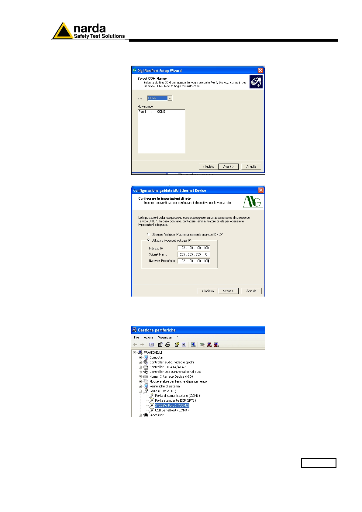
Verify the virtual COM port assigned.
Set the network setting as shown in figure below:
Enter in Peripheral management (Start > Settings> Control Panel >
System>Hardware> Device Manager). The assigned STE02W COM port
can be found in Ports (COM & LPT) – USB Serial Port (COMx).
Select the COM port in order to the 8063SW02 station control panel.(see §
3.11)
8063SW02 - User’s Guide 3-13
Page 62
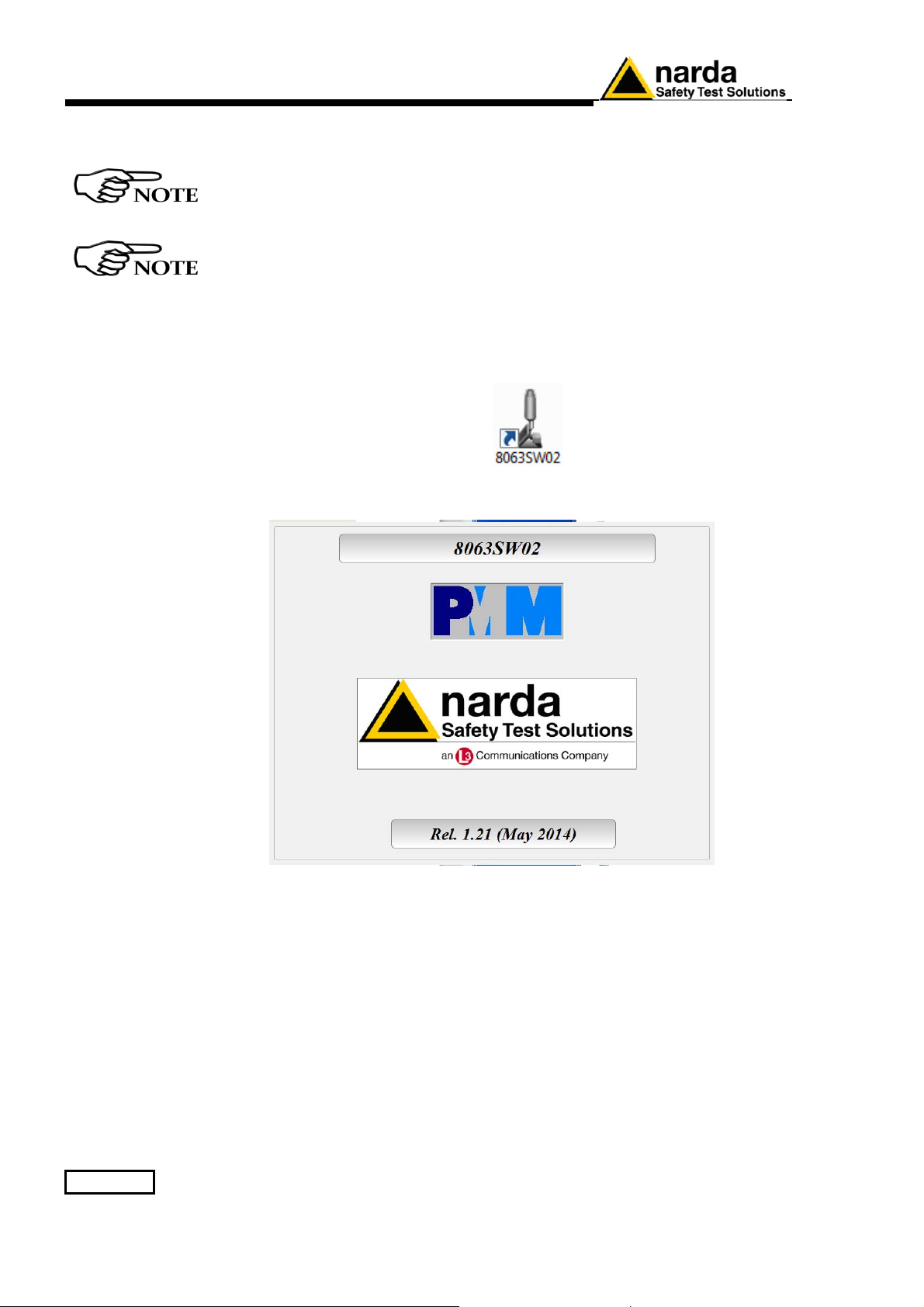
3.10 Starting the
program
Before to start 8063SW02, it is recommended to limit the applications
running on your computer.
The User must have administrator privileges to run the 8063SW02
software in Windows 7 or Windows10; right click on the program .exe
file and click on “Run as administrator” to temporarily run the
program or application as an administrator until close it (Windows 7
also allows to mark an application so that it always runs with
administrator rights).
Click twice on the 8063SW02 icon to start the software
First a window appears displaying the software release.
3-14 8063SW02 - User’s Guide
Page 63
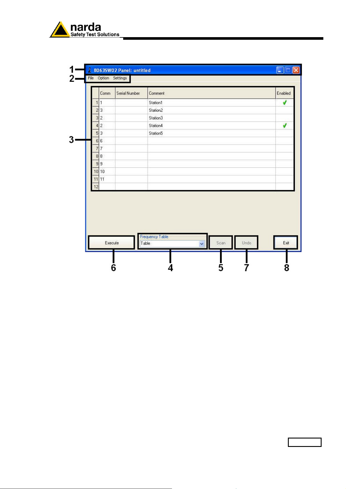
3.11 Main window
The program 8063SW02 main window will be shown
Fig. 3-1 8063SW02 main window
1. Tool bar;
2. Setting menu;
3. Station control panel;
4. Frequency table;
5. Scan button;
6. Execute button;
7. Undo button;
8. Exit button.
8063SW02 - User’s Guide 3-15
Page 64
3.11.1 Tool bar
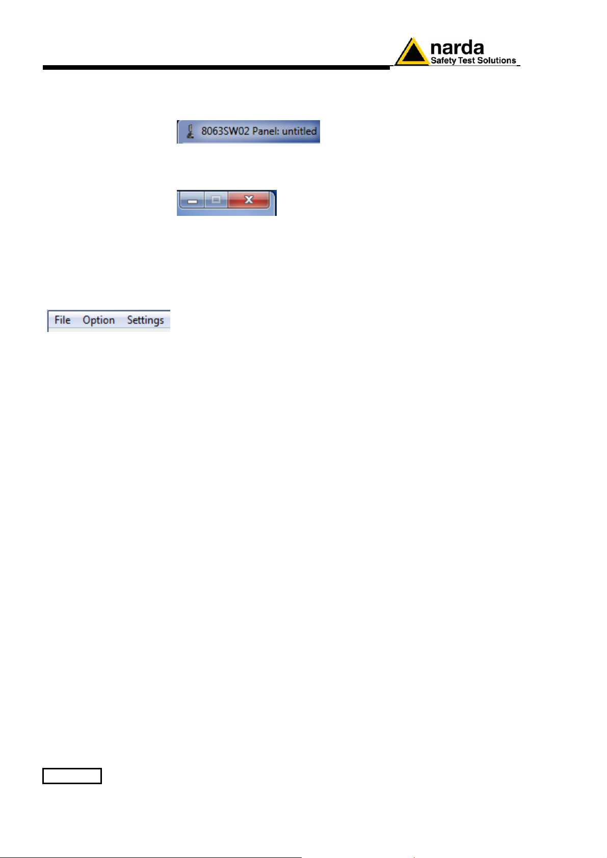
The tool bar shows the icon and name of the software; it is also displayed
the name of the AMS-8063 system loaded on the station control panel.
3.11.2 Setting menu
The control buttons allow to minimize to icon, enlarge/restore the main
window and exit the program.
Commands:
- File: Manage the AMS-8063 system, display the data recorded and show
8063SW02 release information.
- Option: Modify the appearance of the program and sort in ascending
alphabetical or chronological order the “frequency table” saved.
- Settings: Manage the Frequency table and modify measurement and
storing settings.
3-16 8063SW02 - User’s Guide
Page 65
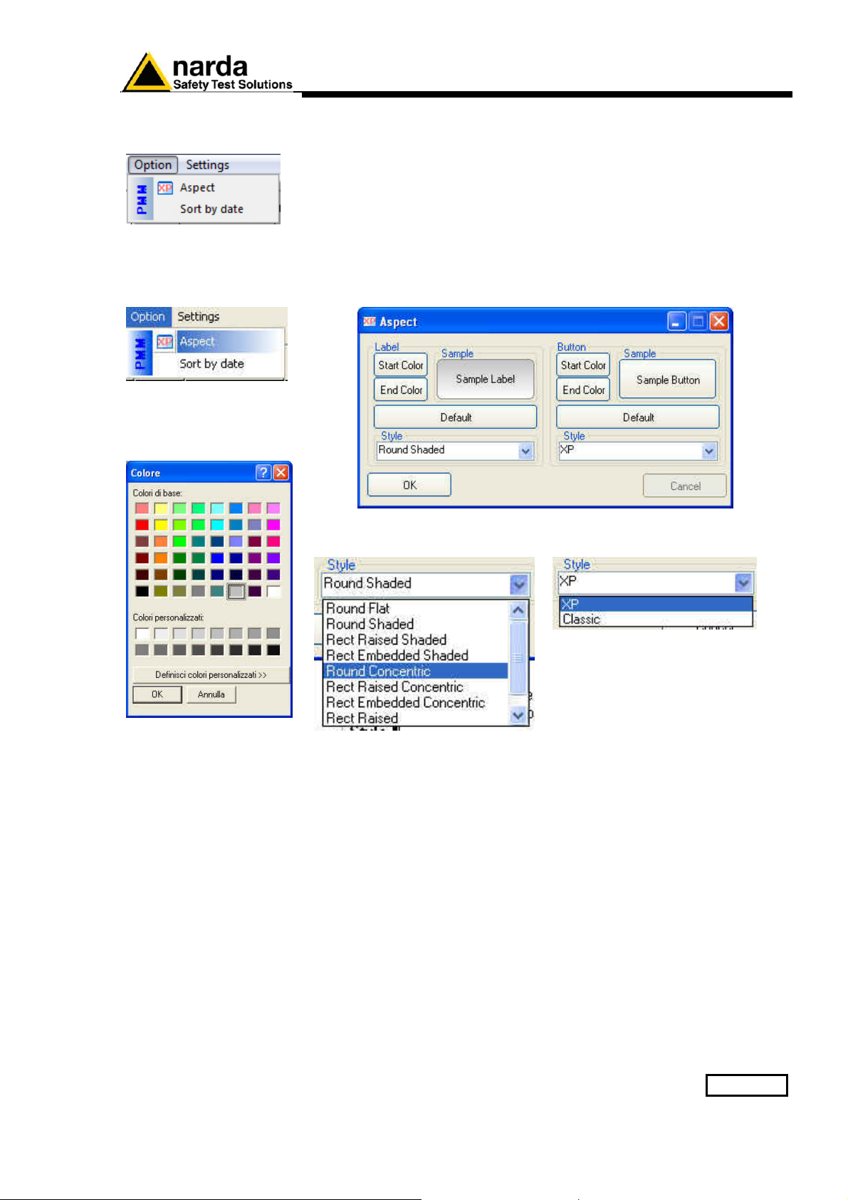
3.11.3 Option
Option menu:
Aspect
Sort by date
3.11.3.1 Aspect
Aspect concerns the appearance of the program:
Buttons and labels styles can be selected from a Style list
Start and End Color buttons allow selection from a color palette
Sample Button and Sample Label show the appearance preview
Default button to set appearance to the default parameters
8063SW02 - User’s Guide 3-17
Page 66
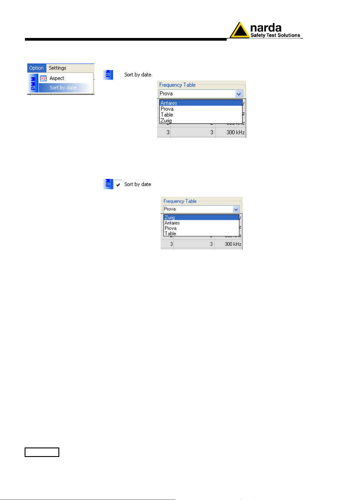
3.11.3.2 Sort by date
If Sort by date is disable the frequency table saved are sorted in
ascending alphabetical order.
If Sort by date is enabled √ the frequency table saved are sorted in
chronological order.
3-18 8063SW02 - User’s Guide
Page 67
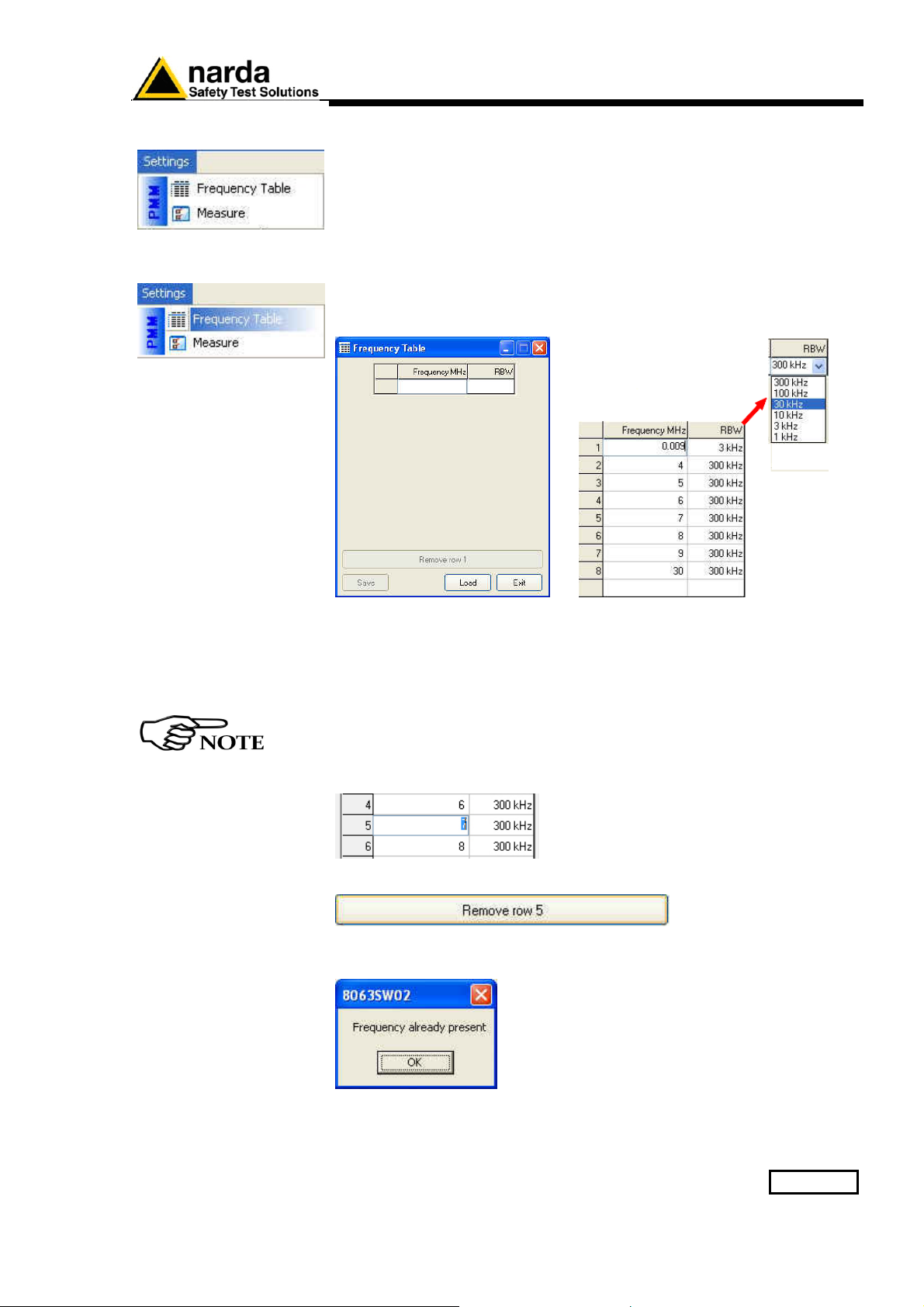
3.11.4 Settings
Settings menu:
- Frequency Table
- Measure
3.11.4.1 Frequency Table
The Frequency table function opens a window to edit the centre frequency
(in MHz) and select the Resolution Bandwidth filter.
The RBW affects the sweep time (the higher RBW, the faster sweep) and
frequency resolution (Lower RBW shows more details in the frequency
axis).
Click the Exit button to go back to the main window
Type centre frequency (in MHz), select among six different settings for the
Resolution Bandwidth filter (1 kHz, 3 kHz, 10 kHz, 30 kHz, 100 kHz e 300
kHz) and confirm with Enter.
As long as the first row is not filled, the “Save” and “Remove Row”
buttons are disabled.
To delete the Row click on the corresponding line (which turns blue) and
select Remove Row (it will show the number of the row selected).
If the centre frequency value is already entered, the following message will
be shown:
When a row is filled at least and select Exit, it will be shown the Save
Frequency window.
8063SW02 - User’s Guide 3-19
Page 68
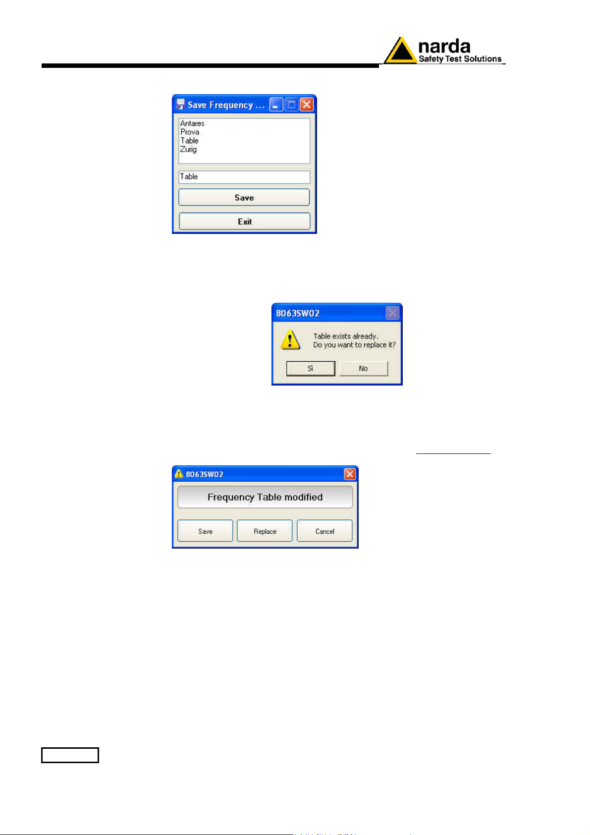
The Save button opens the following window:
← List of the Frequency table
previously saved.
← Type a new name for the
Frequency table (If any name is not
entered, the new frequency table will be
saved with the default name Table).
Select Save to confirm.
If select Exit, the operation will be aborted.
If you type or select a name already entered, the following message will be
shown:
Select Yes to confirm.
If select No, the operation will be aborted
If select Exit after having modified a Frequency table previously saved, it
will be shown the following message:
Select Save to type a new name for the Frequency table or overwrite a
table already present in the list.
Select Replace to overwrite the existing frequency table.
If select Cancel, the operation will be aborted.
3-20 8063SW02 - User’s Guide
Page 69
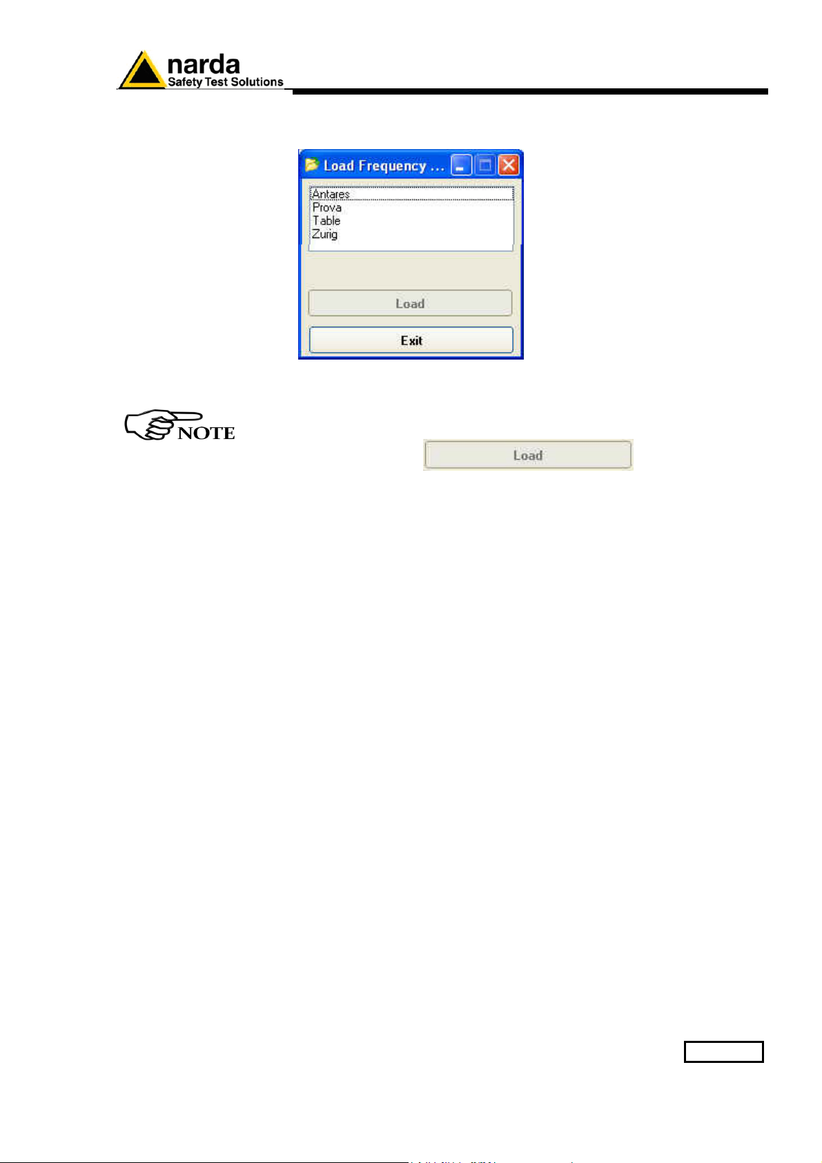
Load button allows to recall a Frequency Table previously saved:
← List of the Frequency table
available.
Select a Frequency table from the list and confirm with Load.
As long as a Frequency table is not selected, the “Load” button is
disabled
Click the Exit button to go back to the main window
8063SW02 - User’s Guide 3-21
Page 70
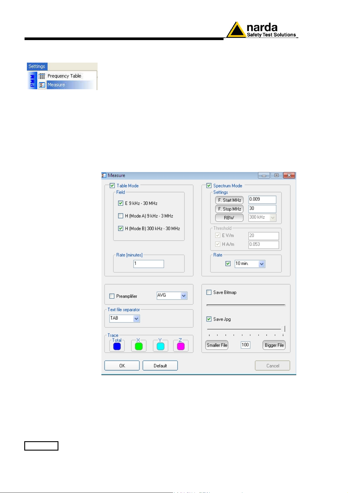
3.11.4.2 Measure
Measure menu:
- Table Mode (Field e Rate [Minutes])
- Spectrum Mode (Settings, Threshold and Rate[Hours])
- Preamplifier
- AVG/RMS
- Text file Separator
- Trace
- Save Bitmap/Save jpg
- OK/Default/Cancel
3-22 8063SW02 - User’s Guide
Page 71
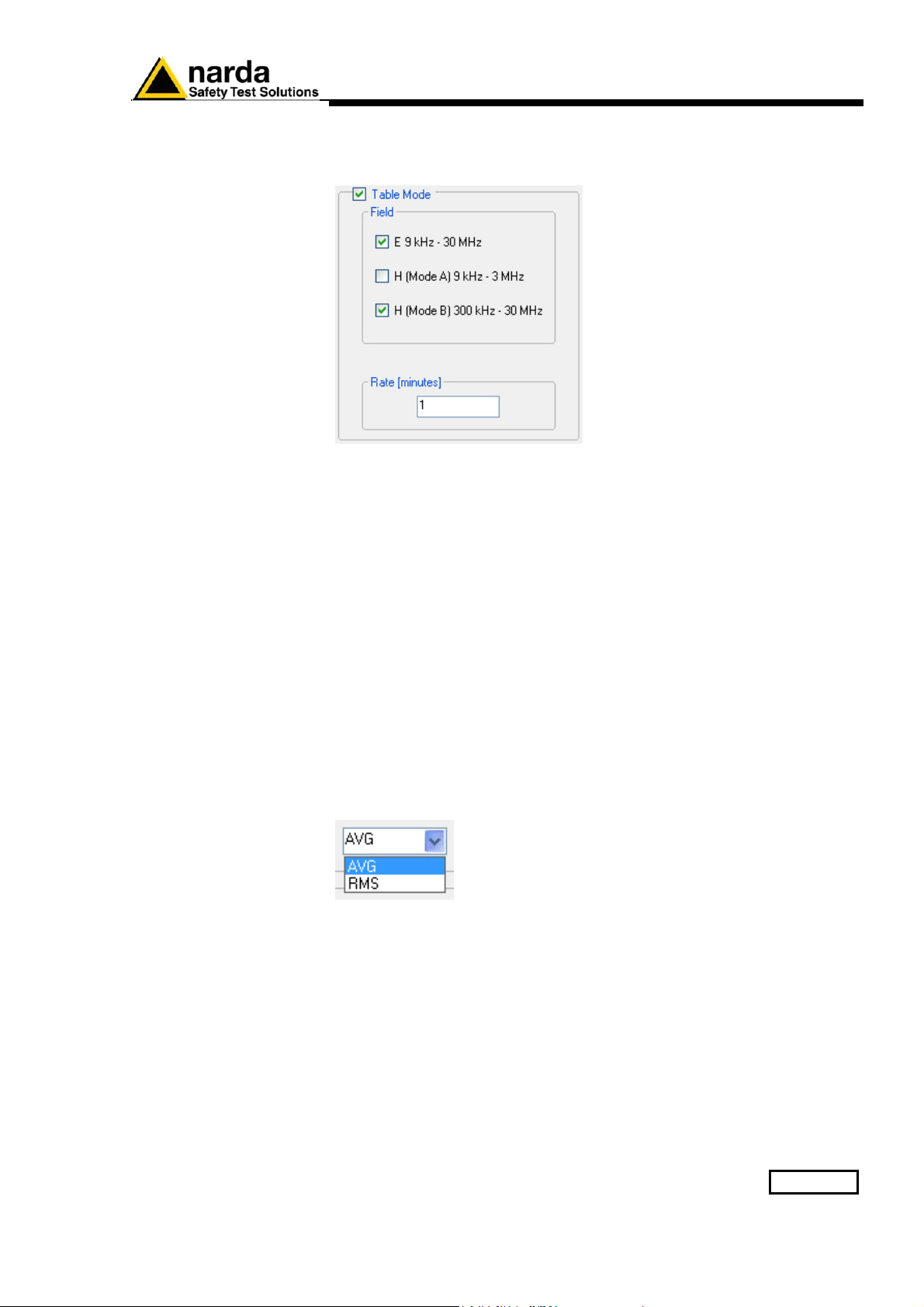
Table Mode
Table Mode section allows to set different acquisition modes and the
storing Rate.
AVG/RMS
Field
Select Electric (E) and/or Magnetic (H) in two different ranges.
E 9 kHz – 30 MHz
H (Mode A) 9 kHz – 3 MHz
H (Mode B) 300 kHz – 30 MHz
Rate [minutes]
Data are saved in the Table_Mode.txt at a frequency (Rate) ranging from
1 minute to 1440 minutes.
This command defines on which average the field levels will be calculated.
The average can be arithmetic (AVG) or quadratic (RMS).
8063SW02 - User’s Guide 3-23
Page 72
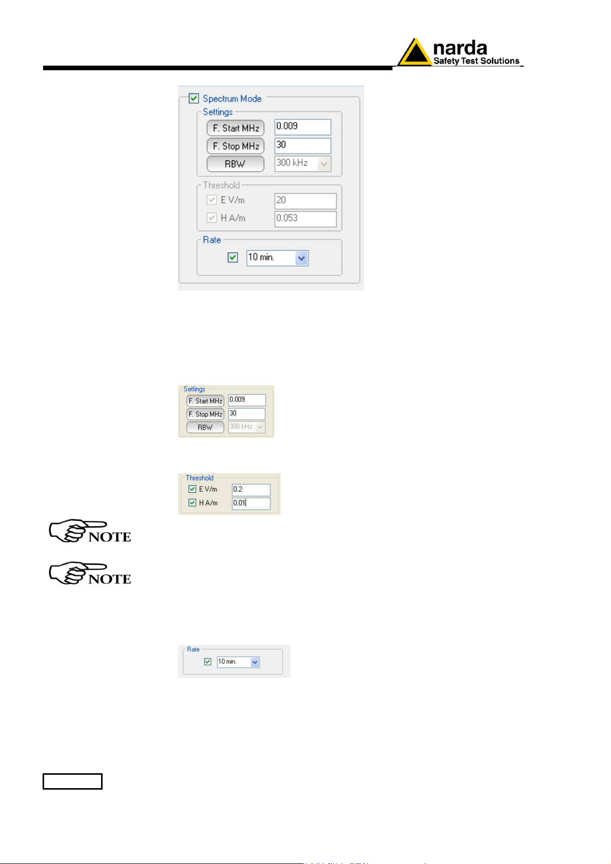
Spectrum Mode
Settings
F. Start MHz, F. Stop MHz: can be set to easily define frequencies to be
displayed.
RBW: the RBW filter is set automatically, depending on the frequency
range.
Threshold: The spectrum analysis is executed when exceeding the
threshold value set for the field intensity.
In the default settings the Threshold is not enabled. Disable the
Rate[hours] to active this function.
The spectrum analysis is executed at the frequency of Rate [hours] or
when exceeding the threshold value.
Rate [hours] indicates after how many hours from the latest scan the
Analyzer has to perform a new one.
The spectrum analysis is performed at a frequency (Rate) of 10, 15, 30
minutes or 1, 2, 3, 4, 5, 6, 12 and 24 hours
3-24 8063SW02 - User’s Guide
Page 73
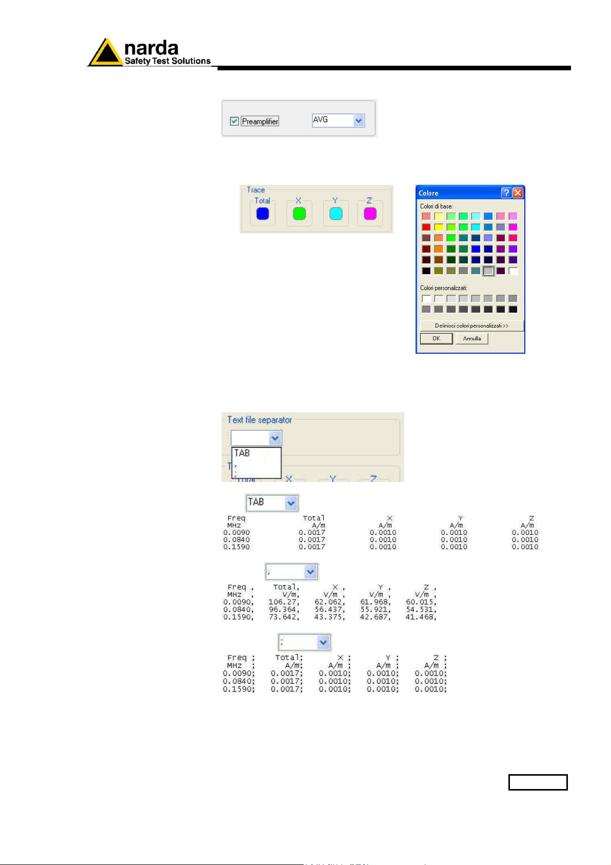
Preamplifier
Preamplifier: for best sensitivity when activated.
Trace
Trace to set trace colours by means of the colour palette
Text file Separator
Select the separator character (tab or comma or semicolon) to set the
separator character between each column in the TXT file.
- tab
- comma
- semicolon
8063SW02 - User’s Guide 3-25
Page 74
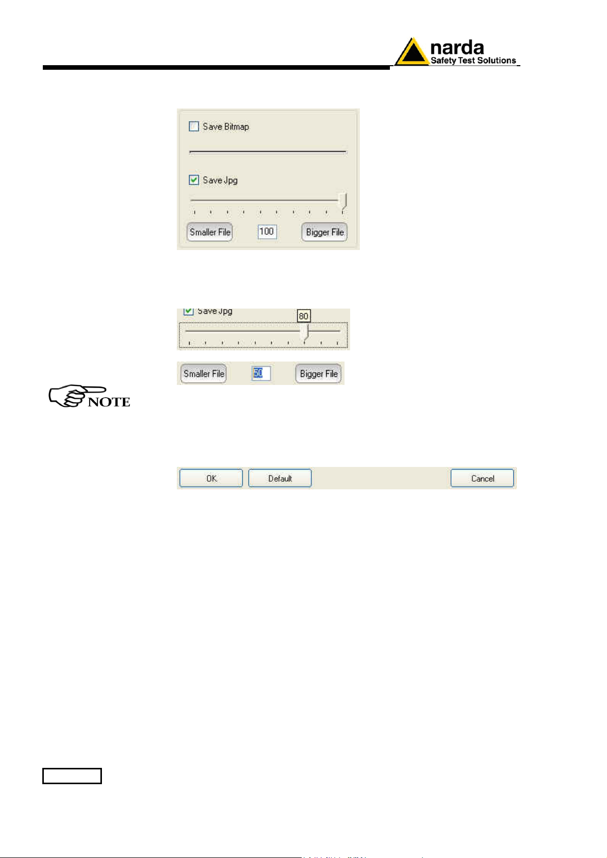
Save Bitmap/Save jpg
It allows to define the quality of the image copied in the graph area.
In the Factor Quality window drag the slider arrow left or right to change
the balance between size and quality; you can also use the box to set the
exact percentage.
The best compromise between quality and dimensions is around
90%.
OK/Default/Cancel
Select OK to save the new setting and go back to the main window.
Select Default to completely restore the initial setting.
If select Cancel, the operation will be aborted without saving.
3-26 8063SW02 - User’s Guide
Page 75
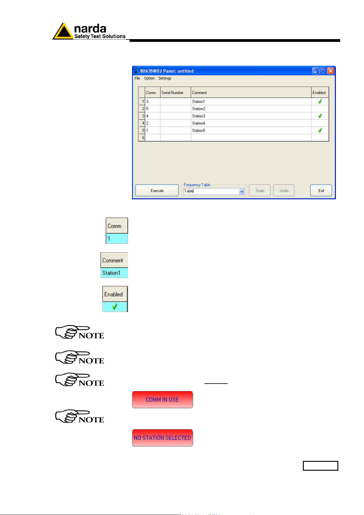
3.11.5 Station control
panel
The Station control panel includes the list of all AMS-8063 installed.
To enter a new Station proceed as follows:
Comm: Select the COMM port available.
Comment: Type the name of the monitoring station.
On the “Enabled” column of the control panel, tick √ the station to be
queried.
UNDO button to erase the last change.
As soon as the station is queried, the serial number will be displayed;
the number will appear till the software is not closed.
If two or more stations enabled have the same COMM port number
assigned, the following message will be shown.
As long as a station is not listed, the following message will be
shown:
8063SW02 - User’s Guide 3-27
Page 76
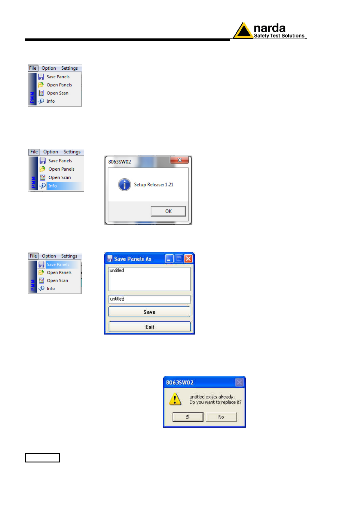
3.11.6 File
File menu:
- Save Panels;
- Open Panels;
- Open Scan (see Chapter 4).
3.11.6.1 Info
- Info
Click Info to display the software release currently installed on the PC
.
3.11.6.2 Save Panel
Save Panels allows to save the group of all AMS-8063 listed to a file.
Select Save to confirm.
If select Exit, the operation will be aborted.
If you type or select a name already entered, the following message will be
shown:
← List of Systems previously
saved.
← Type a new name of the System
(If any name is not entered, the new
System will be saved with the
default name untitled).
Select Yes to confirm.
If select No, the operation will be aborted
3-28 8063SW02 - User’s Guide
Page 77
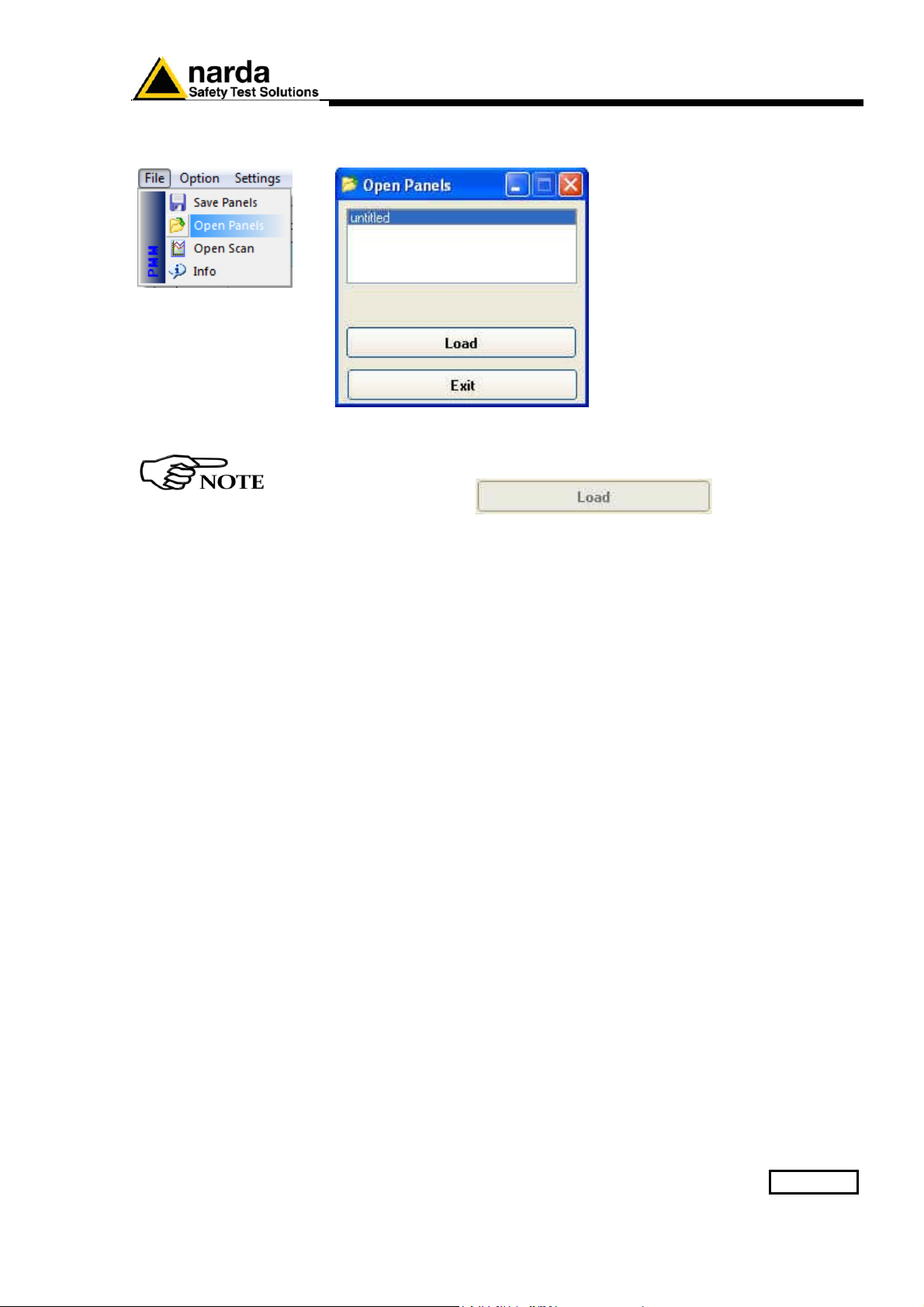
3.11.6.3 Open Panels
Open Panels allows to recall a group of AMS-8063 previously saved
← List of the System available.
Select a System from the list and confirm with Load.
As long as a System is not selected, the “Load” button is disabled
Click Exit to go back to the main window
8063SW02 - User’s Guide 3-29
Page 78
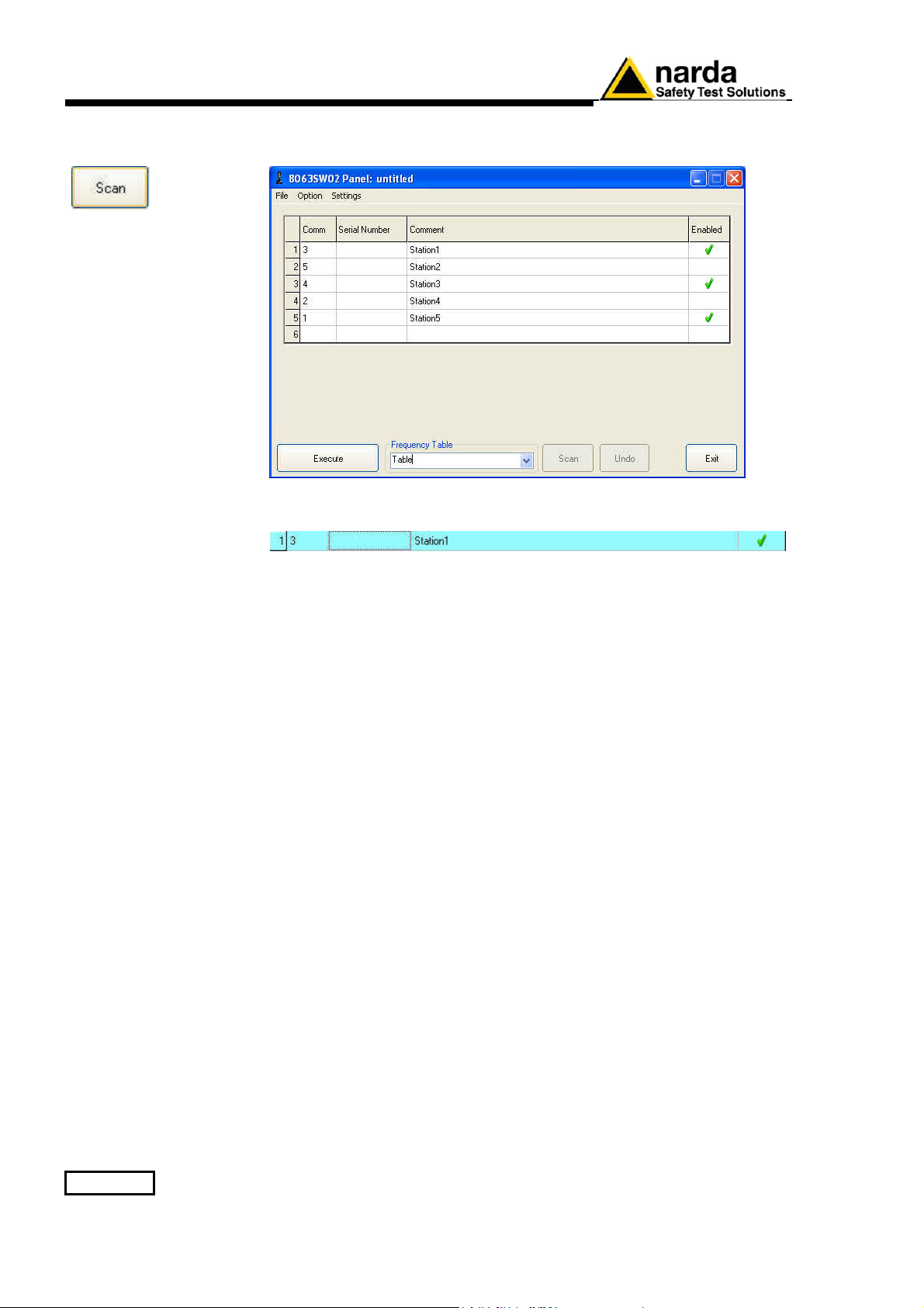
3.11.7 SCAN
SCAN: requests instantaneous field value (single query – not continued).
With √ enable the station to be queried (which turns blue).
Press SCAN button to query the station enabled.
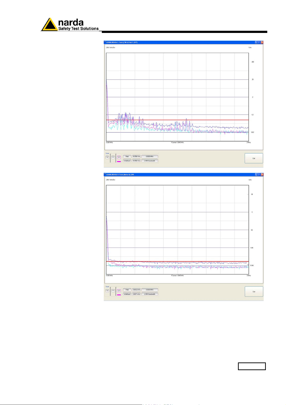
Depending on the settings (see Settings/Measure), it will be displayed the
spectrum of the Electric and/or Magnetic field with automatic generation of
graph (.JPG or .BMP) and
table (.TXT).
The analyzer stay ON for the minimum time necessary to perform the scan
on the 3 axis simultaneously and store the data.
If both Electric and Magnetic (Mode A or Mode B) field are enabled, they
will appear in sequence.
3-30 8063SW02 - User’s Guide
Page 79
8063SW02 - User’s Guide 3-31
Page 80
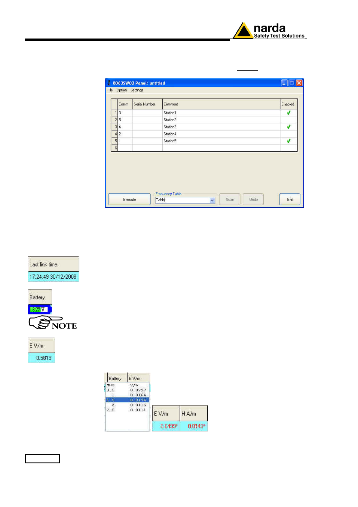
3.11.8 EXECUTE
With EXECUTE button t
system of AMS-8063 monitoring stations.
he software query continuously and cyclically a
To set the querying delay time among AMS-8063 enabled see § 3.7.
With √ enable the station to be queried.
Press EXECUTE button to query the station enabled.
On the Station control panel will be displayed new indicators as:
- Last link time: date of the latest connection made;
- Battery: The internal control system of the Analyzer features a voltmeter
for continuous measurement of the battery voltage. This function ensures
constant control of the power situation for correct operation of the system.
The default values of the battery are 3.6V (Threshold minimum) e 4.4V
(Threshold maximum).
- E V/m: show the instantaneous electric field value; simply move the
mouse cursor above the value to display some frequencies and value
previously read by the station.
When the field exceeds the threshold set, the value will be displayed in red
with asterisks (*).
3-32 8063SW02 - User’s Guide
Page 81
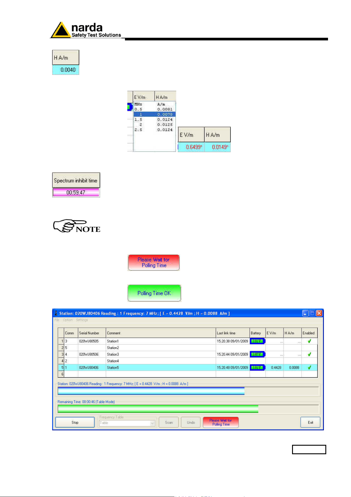
- H A/m: show the instantaneous magnetic field value; simply move the
mouse cursor above the value to display some frequencies and value
previously read by the station.
When the field exceeds the threshold set, the value will be displayed in red
with asterisks (*).
- Spectrum inhibit time: The analyzer collects and display the data till the
Spectrum inhibit time is not expired; after that the analyzer performs the
scan on the 3 axis simultaneously and store the data for the time
necessary.
In the Setting/Measure/Rate[hours]
enter a submultiple of 24 hours
defining the daily rate at which the operation has to be repeat.
The “Spectrum inhibit time” function is active if the “Rate[hours]” is
enabled.
After pressing the EXECUTE button, the program performs a check of the
system (called "Polling Time").
At the end of the check, it will be displayed “Polling Time OK”.
8063SW02 - User’s Guide 3-33
Page 82
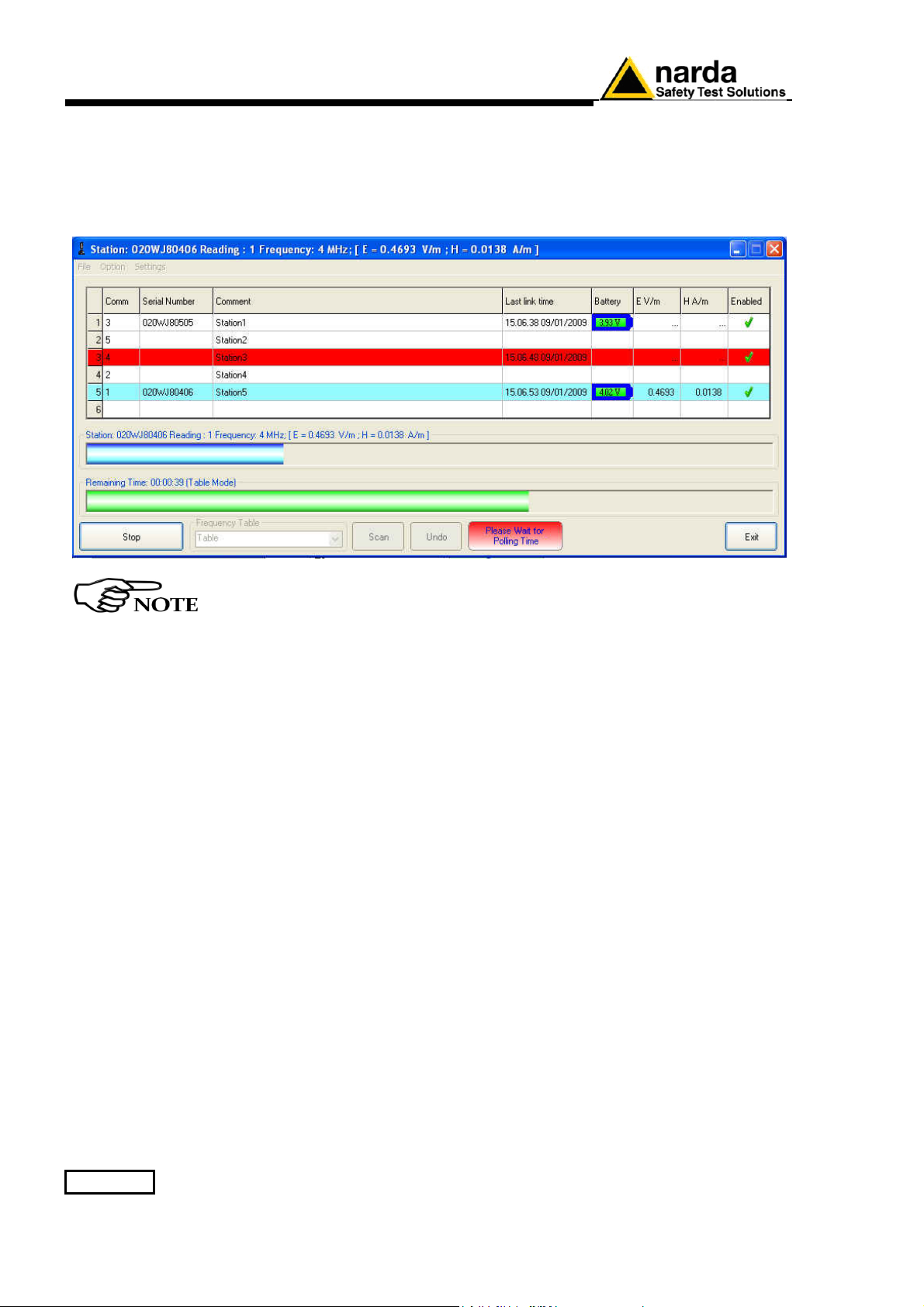
If a station is not connected or the communication is not established, the
row turns red; the EHP-8063 will automatically switch off after about 3
minutes and the battery will be charged.
The connection is reestablished, when the battery voltage will be above
3,05 V.
The connection can be established while the software is running; at
the next cycle, the software will recognize the station just connected.
3-34 8063SW02 - User’s Guide
Page 83
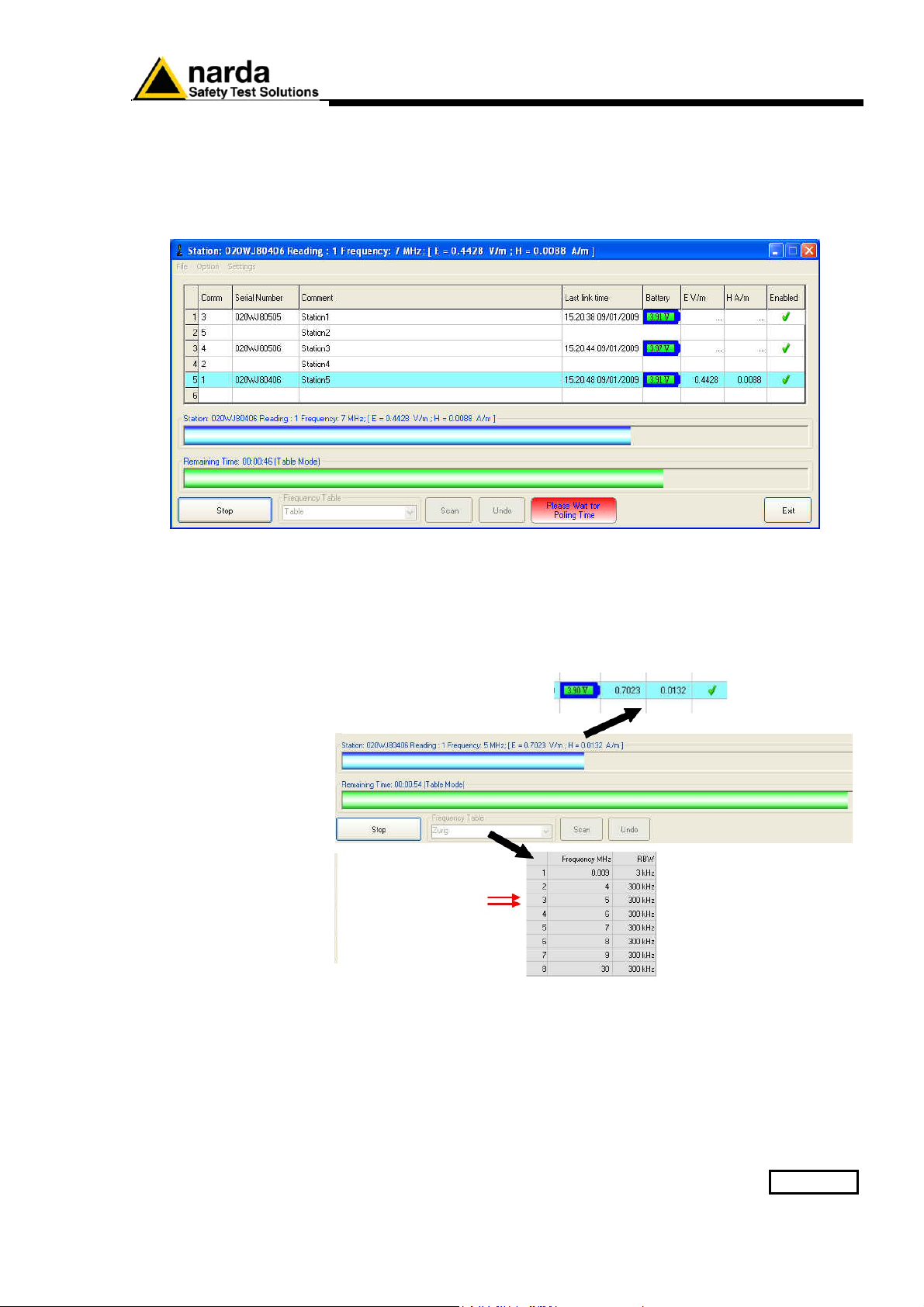
3.11.9 8063SW02
Operating principle
For each station the 8063SW02 performs a continued and cyclical check;
Once the connection between PC and Station is established the software
will show the Serial Number, the date of the latest connection, the battery
voltage and the measured instantaneous electric and magnetic field value.
Move the mouse cursor above the serial number to display the firmware
release currently installed on the station.
When the station is queried (which turns blue), a blue progress bar is
displayed showing the measured instantaneous electric and/or magnetic
field value for each frequency present in the Frequency Table (the value
is also shown in the E V/m and/or H A/m column).
The Reading parameter indicates the number of the value read and stored
in the Table_Mode.txt file in the interval of elapsed time which is shown by
the green progress bar.
The analyzer also collects and displays the data till the Spectrum inhibit
time is not expired (Rate[hours]) or when exceeding the threshold value
set for the field intensity (Threshold). After that, the analyzer performs the
scan on the 3 axis simultaneously and store the data for the minimum
necessary time only; the operation is repeated at the set daily Rate or
when a new Threshold event occur.
8063SW02 - User’s Guide 3-35
Page 84
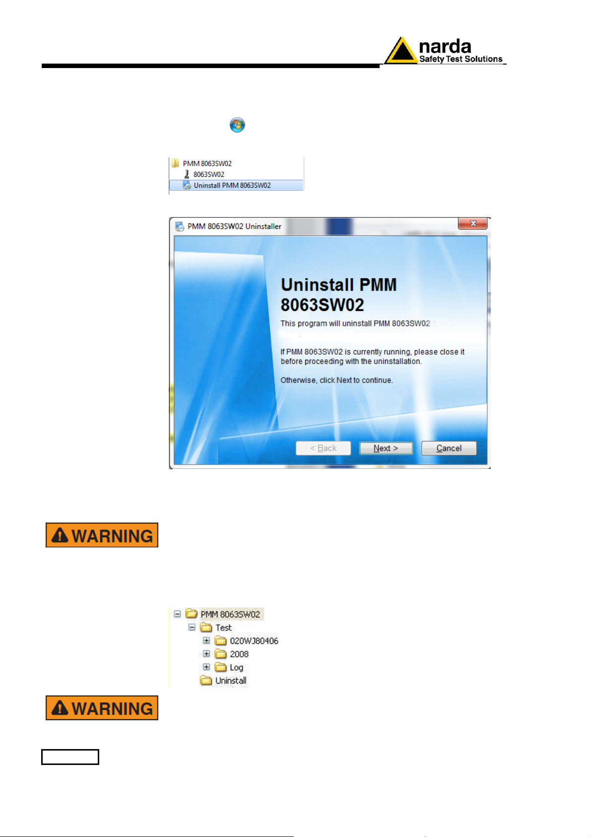
3.12 Uninstalling
Software
It is possible to remove the 8063SW02 software from the PC according to
the following procedure:
Exit from the 8063SW02 program.
Select Start ( ) All Programs PMM 8063SW02 and then click on
Uninstall PMM 8063SW02.
Follow the uninstaller instructions
The software is now removed from the system; click Finish to close
uninstaller utility
Before removing any shared system file, the uninstaller will ask for a
confirmation.
Answer “NO” in case you are not sure whether the showed system file
is required for other applications.
The destination folder will not be deleted to preserve the data
downloaded and the Log file.
It is suggested to make a backup of the destination folder for future
needs before deleting it.
3-36 8063SW02 - User’s Guide
Page 85
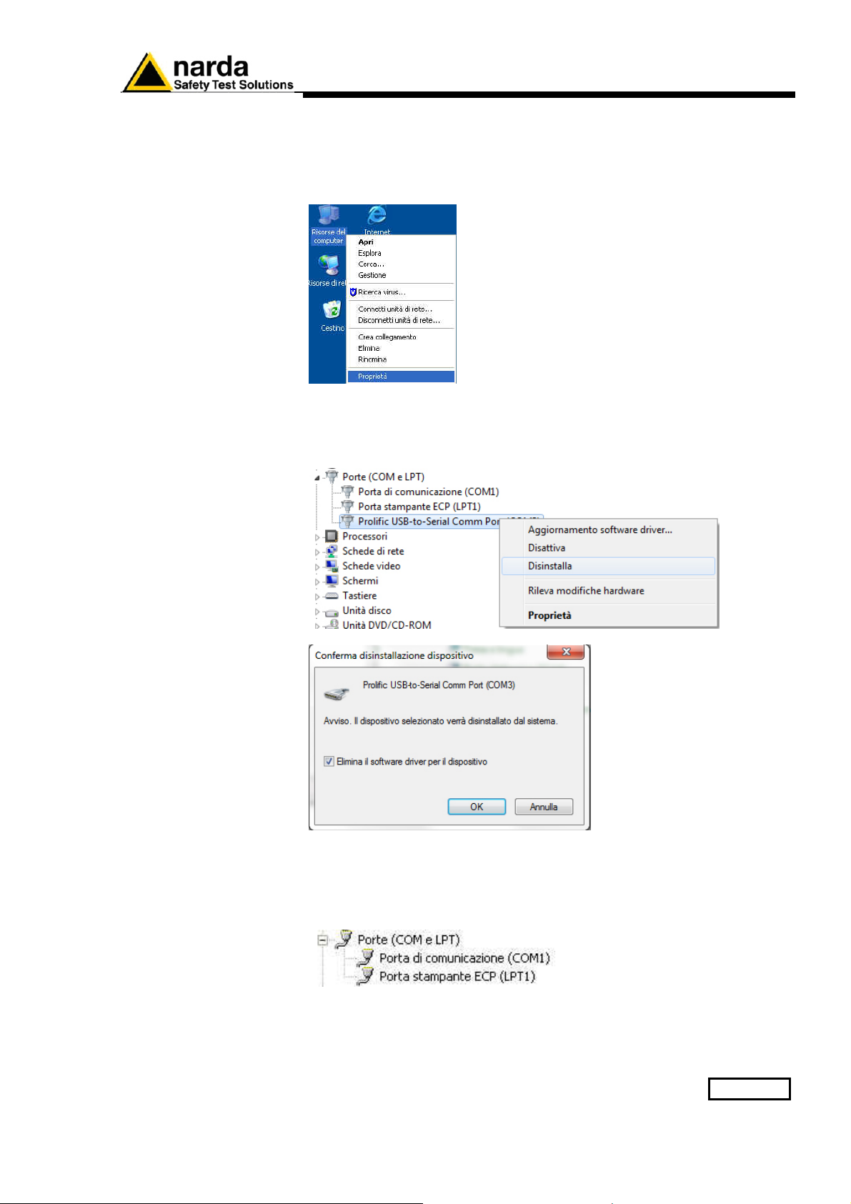
3.13 Uninstalling the
driver of RS232 USB adapter
(optional)
Apply this method if the driver uninstaller (normally supplied with the
hardware) is not available.
Right click on Computer icon to access Properties
Select Hardware and Device Manager.
Click + to expand Porte (COM e LPT).
Right click on Prolific USB-to-Serial Comm Port (COMx) and Uninstall.
Then confirm by selecting OK.
Once the uninstall is completed the peripheral Prolific USB-to-Serial
COMM Port (COMx) will be removed.
8063SW02 - User’s Guide 3-37
Page 86

This page has been intentionally left blank
3-38 8063SW02 - User’s Guide
Page 87
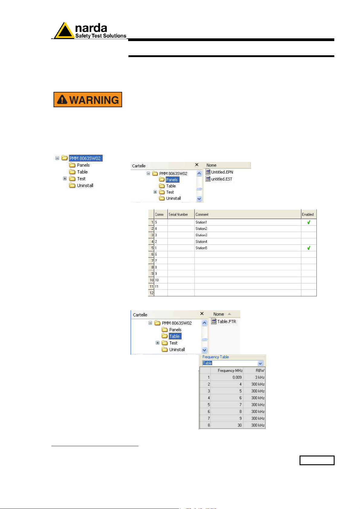
4.1 Introduction
4.2 Data management
4.2.1 Installation folder
structure
4 – Data display
This section provides information for correct display and interpretation of
the data downloaded from the AMS-8063 Area Monitor System using the
8063SW02 software.
To ensure the program runs correctly it is important not to rename or
move the saved files.
The installation folder has an intuitive structure that allows an easy
management of data acquired.
The installation folder includes:
- Panels: Each list of AMS-8063 is stored in a file.
Untitled.EST file
preview
Table.FTR file
preview
- Table: Each file contains a Frequency Table.
1
Document AMS8063EN-71005-1.22 - © NARDA 2017
Data display 4-1
Page 88
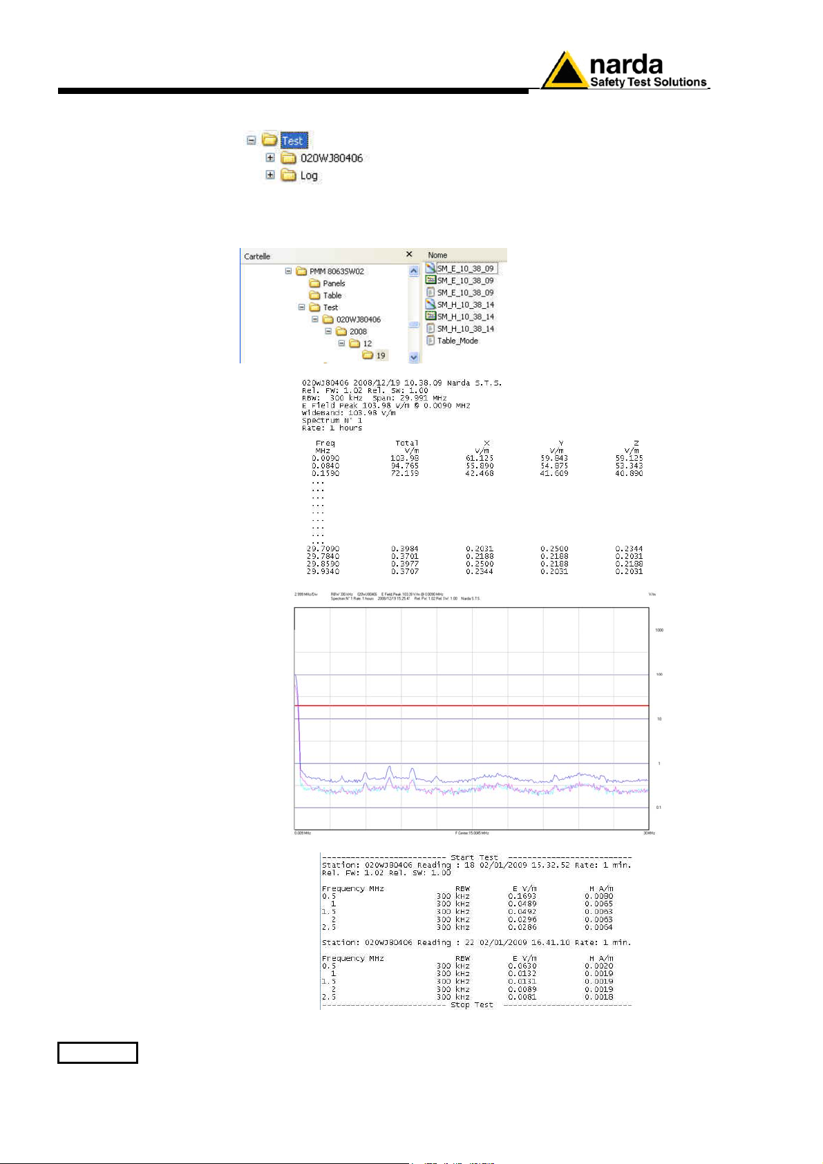
SM_E_10_38_09.txt file
preview
SM_E_10_38_09.bmp and
SM_E_10_38_09.SPC file
preview
Table_mode.txt file
preview
- Test: This folder contains all data acquired and the Log file.
(020WJ80406). When a new monitoring station is installed, a new folder is
created in the Test directory. The folder is created to collect the data every
time the AMS-8063 station is queried, dividing them by year (2008), month
(12) and day (19).
4-2 Data display
Page 89
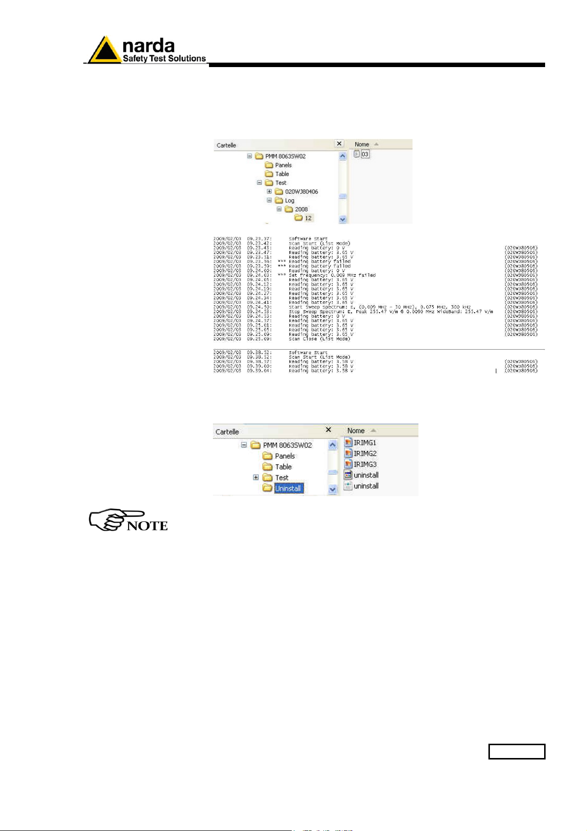
03.txt file
preview
- Log: All activities requested by manual interventions of the user or done
automatically by the AMS-8063 are registered into a file whose name
corresponds to the day that the event occurred.
The Log folder collects the “day” file dividing them by year (2008) and
month (12).
- Uninstall: This folder contains some file of the 8063SW02 uninstall
software.
By using Word or Excel application, click “File” and “Open”, select
“Type of file: all files”, follow the path “Destination folder/Test/Station
name/year/month/day”, select the file and confirm with “Open”.
Data display 4-3
Page 90
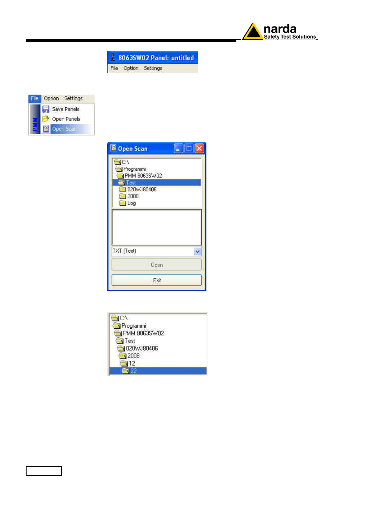
4.3 Data display
4.3.1 Main commands
4.3.1.1 Open Scan
In the File menu, the Open Scan function allows:
- Display the data recorded in graph and
table format (Data folder).
- Open the Log file where all activities are registered (Events folder).
Data folder
← Test folder structure
← List of the file available
← list of filename extension
available
Follow the path Station name/Year/Month/day.
4-4 Data display
Page 91
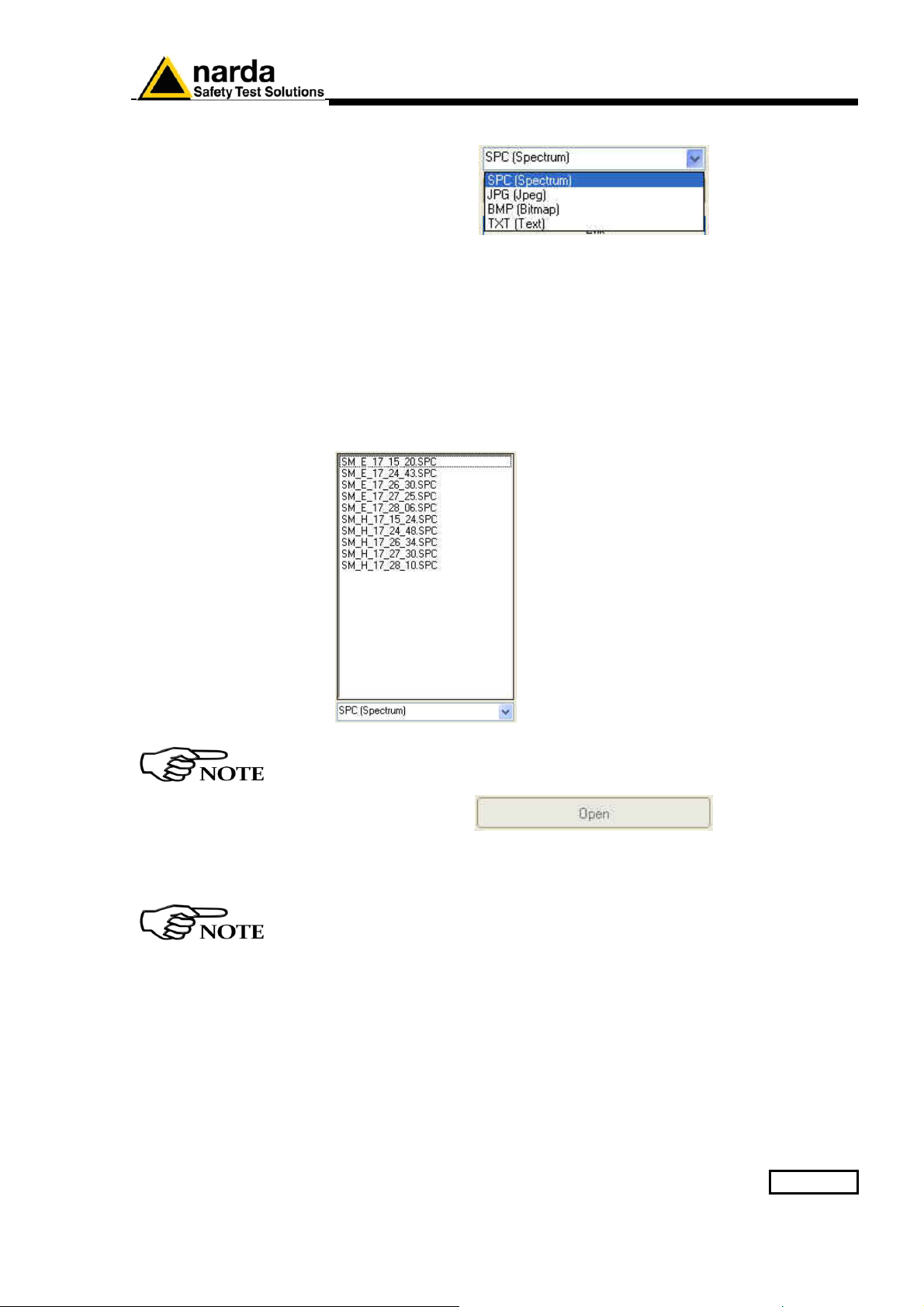
List of filename extension includes:
- SPC [Spectrum] (*.SPC). Properties file.
- JPG [Joint Photographic Experts Group] (*.JPG). jpeg image file
- BMP [BitMaP] (*.BMP). bitmap image file
- TXT [Text] (*.TXT) Text file
The list of file available will be displayed in order to the type of extension
selected:
Select the file and confirm with Open.
As long as the file is not selected, the “Open” button is disabled
Click Exit to go back to the main window.
By using Word or Excel application, click “File” and “Open”, select
“Type of file: all files”, follow the path “Destination folder/Test/Station
name/year/month/day”, select the file and confirm with “Open”.
Data display 4-5
Page 92
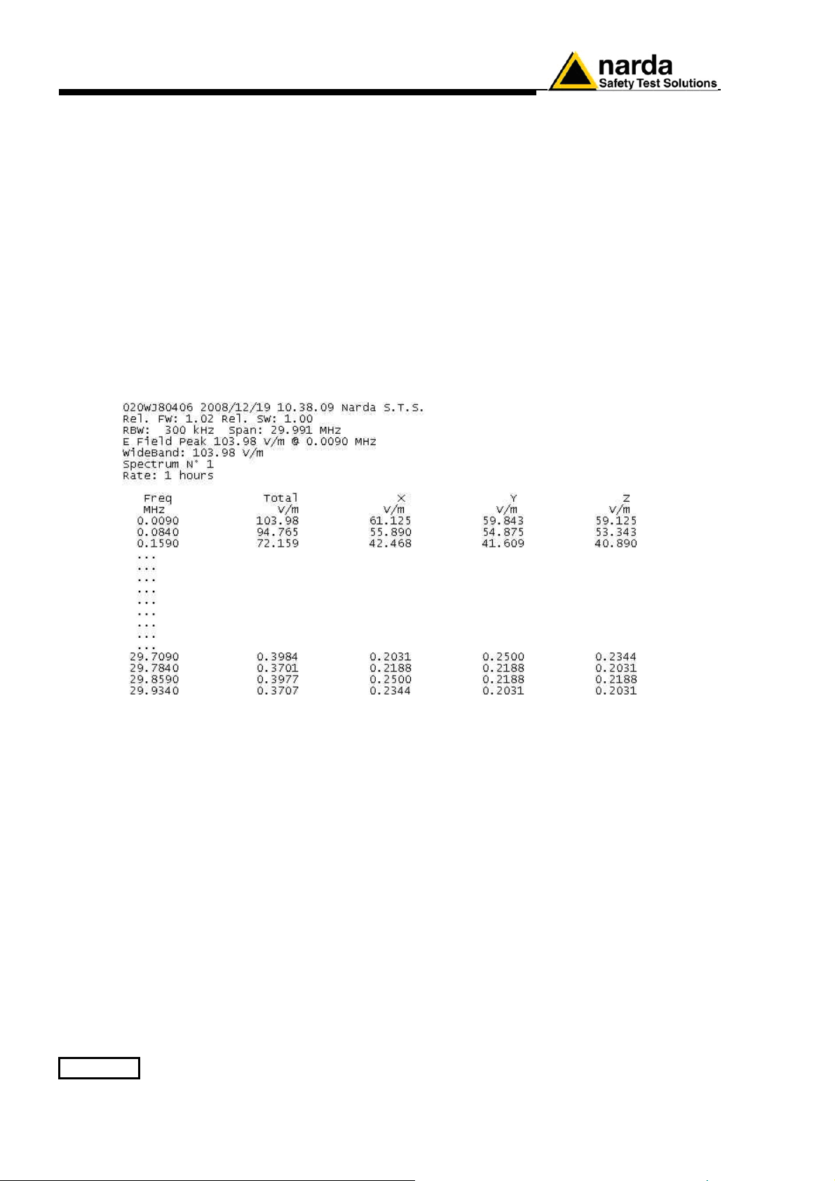
Structure of the .TXT file
The Electric and/or Magnetic field value acquired in Spectrum mode will be
stored in text format (see Settings/Measure/Spectrum Mode/Settings).
The .TXT file name shows the type of the field acquired and at which Hour,
Minute and Second of the day it was detected.
An example of file name is
-
SM = Spectrum mode
-
E = Electric field
-
10 = Hour
-
38 = Minutes
-
09 = Seconds
SM_E_10_38_09.txt :
SM_E_10_38_09.txt preview:
4-6 Data display
Each column is separated by the separator character previously selected
(see Settings/Measure/Spectrum Mode/ Text File Separator).
Main informations are reported at the left of the top of the table.
When the field exceeds the threshold set, the value will be displayed with
asterisks (*)(see Settings/Measure/Spectrum Mode/Threshold).
Page 93
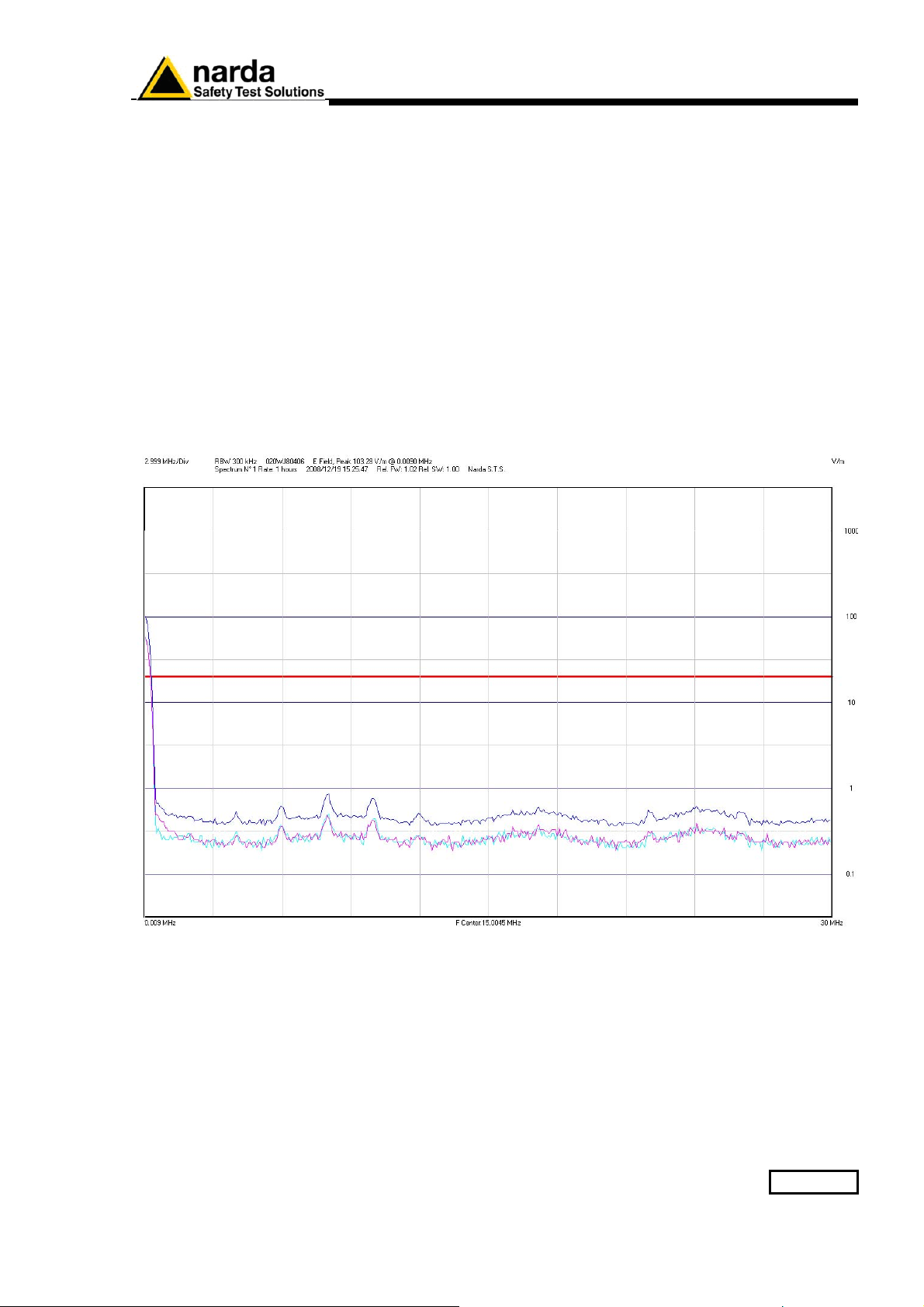
Structure of the
.JPG, .BMP and .PCM file
The Spectrum analysis of the Electric and/or Magnetic acquired field will be
stored in graph format (PCM and BMP or JPG file format). See
Settings/Measure/Spectrum Mode/Settings.
The file name shows the type of the field acquired and at which Hour,
Minute and Second of the day it was detected.
An example of file name is
-
SM = Spectrum mode
-
E = Electric field
-
15 = Hour
-
25 = Minutes
-
47 = Seconds
SM_E_15_25_47.bmp:
SM_E_10_38_09.bmp preview:
Main informations are reported at the left of the top of the image.
The horizontal red line shows the Threshold field (see
Settings/Measure/Spectrum Mode/Threshold).
Data display 4-7
Page 94
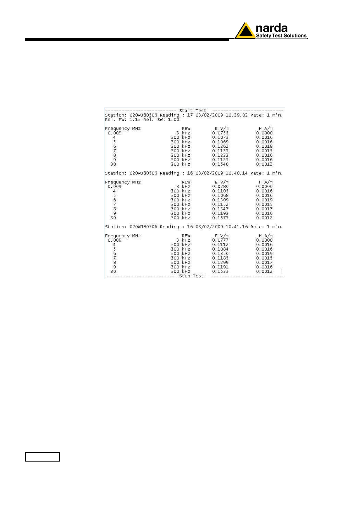
Structure of the
Table.mode.txt file
The Electric and/or Magnetic field value acquired in Table mode will be
stored in the Table.mode.txt file used by all station.
The Reading parameter indicates the number of the value read in the time
interval set (Rate).
Table_mode.txt preview:
4-8 Data display
Page 95
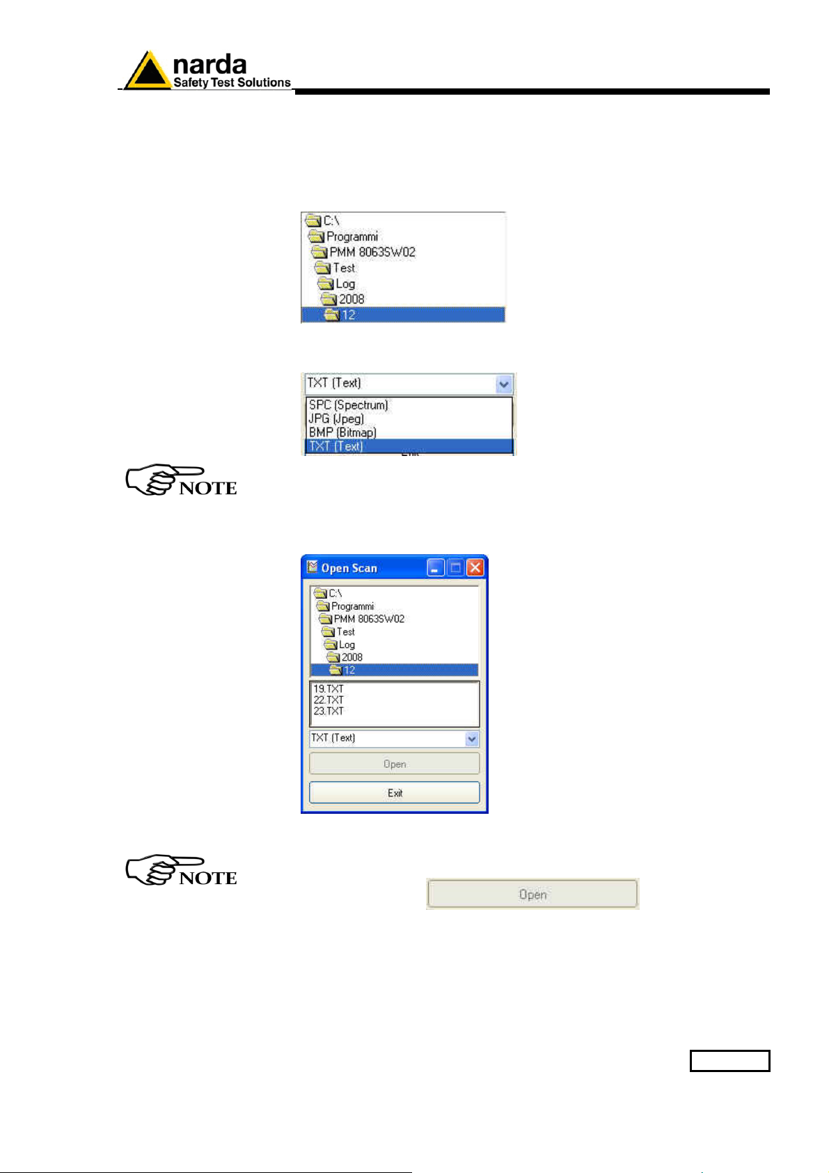
Event folder
The Open scan function also allows to display the Log file where all
activities requested by the user or done automatically by the AMS-8063
are registered.
Follow the path: Log/Year/Month and select the day.
Select TXT (Text) filename extension.
Must be selected TXT (Text) because all events are stored in text file.
The list of day available will be displayed:
Test folder structure
←
← List of the day available
← list of filename extension available
Select the file and confirm with Open.
As long as the file is not selected, the “Open” button is disabled
Click Exit to go back to the main window.
Data display 4-9
Page 96
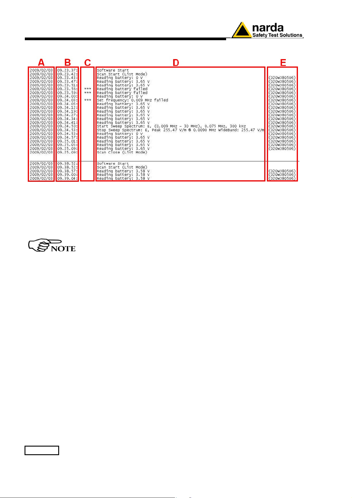
File Log preview:
A column: Data event (Year/Month/Day);
B column: Time event (Hour.Minute.Second);
C column: Three asterisks (***) will be displayed if a problem occur at the
station;
D column: Description of the event;
E column: Serial number of the station.
The horizontal line is shown when the software is closed.
4-10 Data display
Page 97
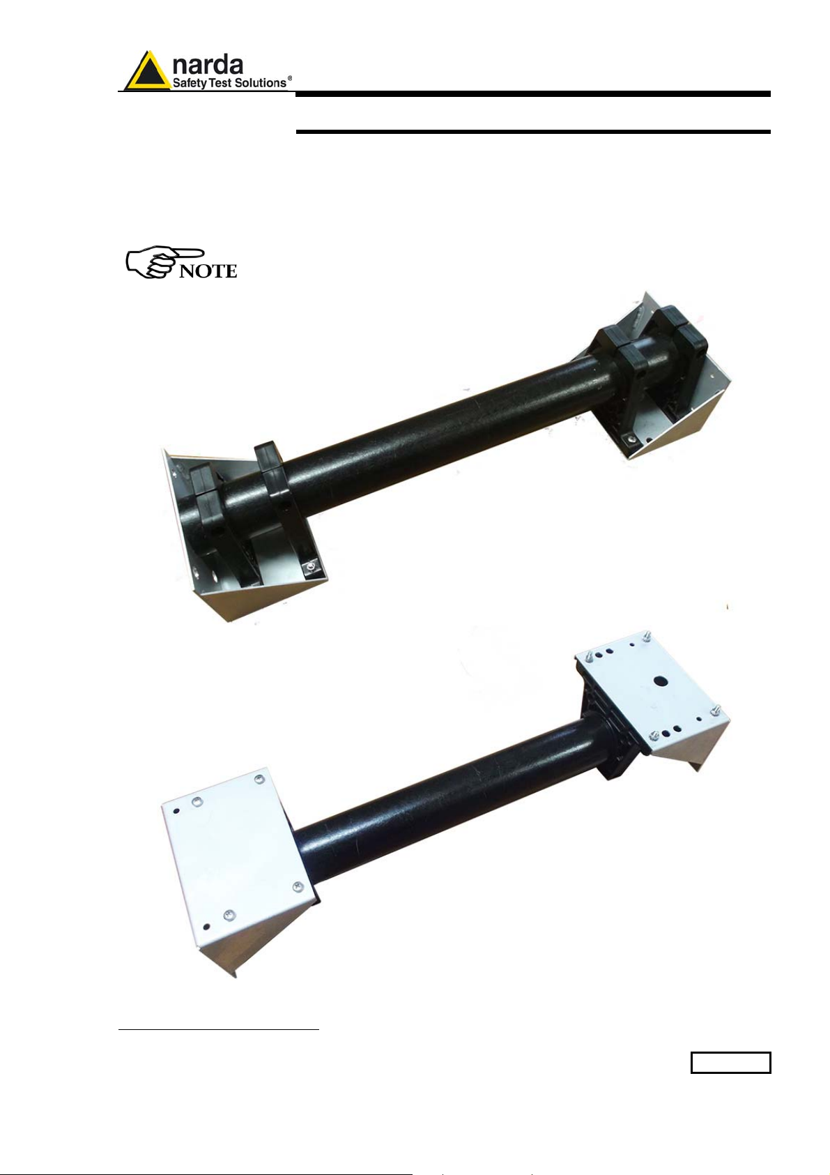
5.1 Introduction
5 – AMS-8063/WMK Wall Mounting Kit
This chapter provides the necessary information for installation of AMS8063 Area Monitor System on the wall by AMS-8063/WMK Wall Mounting
Kit optional accessory.
It also includes information regarding the initial inspection, working
environment, assembly, cleaning, storage and shipment.
Wall Mounting Kit, optional accessory, is available for all AMS-8063
models.
Document AMS8063EN-71005-1.22 - © NARDA 2017
Fig. 5-1 AMS-8063/WMK Wall Mounting Kit
AMS-8063/WMK Wall Mounting Kit 5-1
Page 98
5.2 Initial inspection
5.3 Working environment
5.4 Returning for repair
5.5 Cleaning
Check the package for any damages.
If the packing materials or protective materials are damaged, check
the equipment and make sure it is complete with all parts and intact,
without any mechanical or electrical damage.
Check the accessories with reference to the packing list enclosed
with the device.
Report any damages at once to the shipping company and to NARDA.
The working environment for the accessories, unless specified otherwise,
must be in the following ranges:
• Temperature
•
Relative humidity
from -20°C to +50°C
< 95%
The accessories should be stored in a clean, dry place free of acids, dusts
and humidity.
The storage environment must be in the following ranges:
• Temperature
• Relative humidity (without condensation)
from -20°C to + 70°C
< 99% relative
Any part of the instrument can only be replaced by NARDA, therefore, in
case of damage to parts and/or malfunctions, contact the NARDA service
center.
When the instrument has to be returned to NARDA for repair, the User is
kindly requested to fill out the questionnaire enclosed with this User’s
Manual and write all the required service information and a full description
of the malfunction, to enable NARDA to repair the device in the shortest
possible time.
To reduce the time necessary for the repair, be as specific as possible in
describing the malfunction. If the problem only occurs under specific
conditions, detail in the best possible way how to reproduce these
conditions.
Whenever possible, use the original packing when returning items, and
make sure to wrap the device in heavy paper or plastic.
If the original package material is no longer available, use a sturdy card
box and a sufficient quantity of impact absorbing material all around the
equipment to provide a tight fit and prevent its moving inside the packing.
In particular, take every precaution to protect the solar panels.
Seal the packing securely and write FRAGILE on the container to
encourage better care in handling.
Use a clean, dry, soft cloth to clean the instruments.
Do not use solvents, acids, turpentine, acetone or similar products to
clean the instruments to prevent damages.
5-2 AMS-8063/WMK Wall Mounting Kit
Page 99
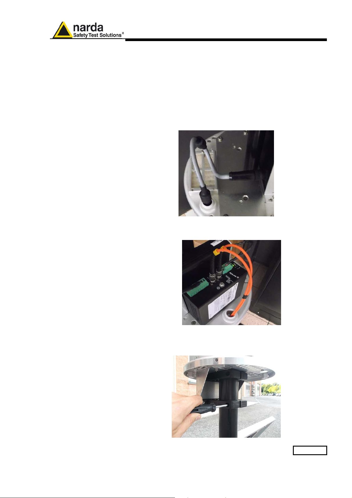
5.6 Installation
AMS-8063/WMK is an easy to install kit to transform the well-known AMS8063 Area Monitor System, usually adopted for ground installation, in a
version designed to be mounted on the wall:
1. Remove the four screws and take off along its axis the protective case
from the monitoring unit.
2. Switch the EHP-8063 off;
3. Unplug the power supply connector from the 8063-Shutter holding by
the plastic part; remove the power cable from the baseplate
unscrewing the nut.
4. Disconnect the Fiber optic from the Optical converter holding by the
metallic part; remove the Fiber optic from the baseplate unscrewing the
nut (AMS-8063-02 only).
5. Disconnect the RS232 cable (AMS-8063-01 only).
6. Remove the receiver unit from the pole unscrewing the Pan head
screw inside the both PA6 black brackets without losing it completely.
AMS-8063/WMK Wall Mounting Kit 5-3
Page 100
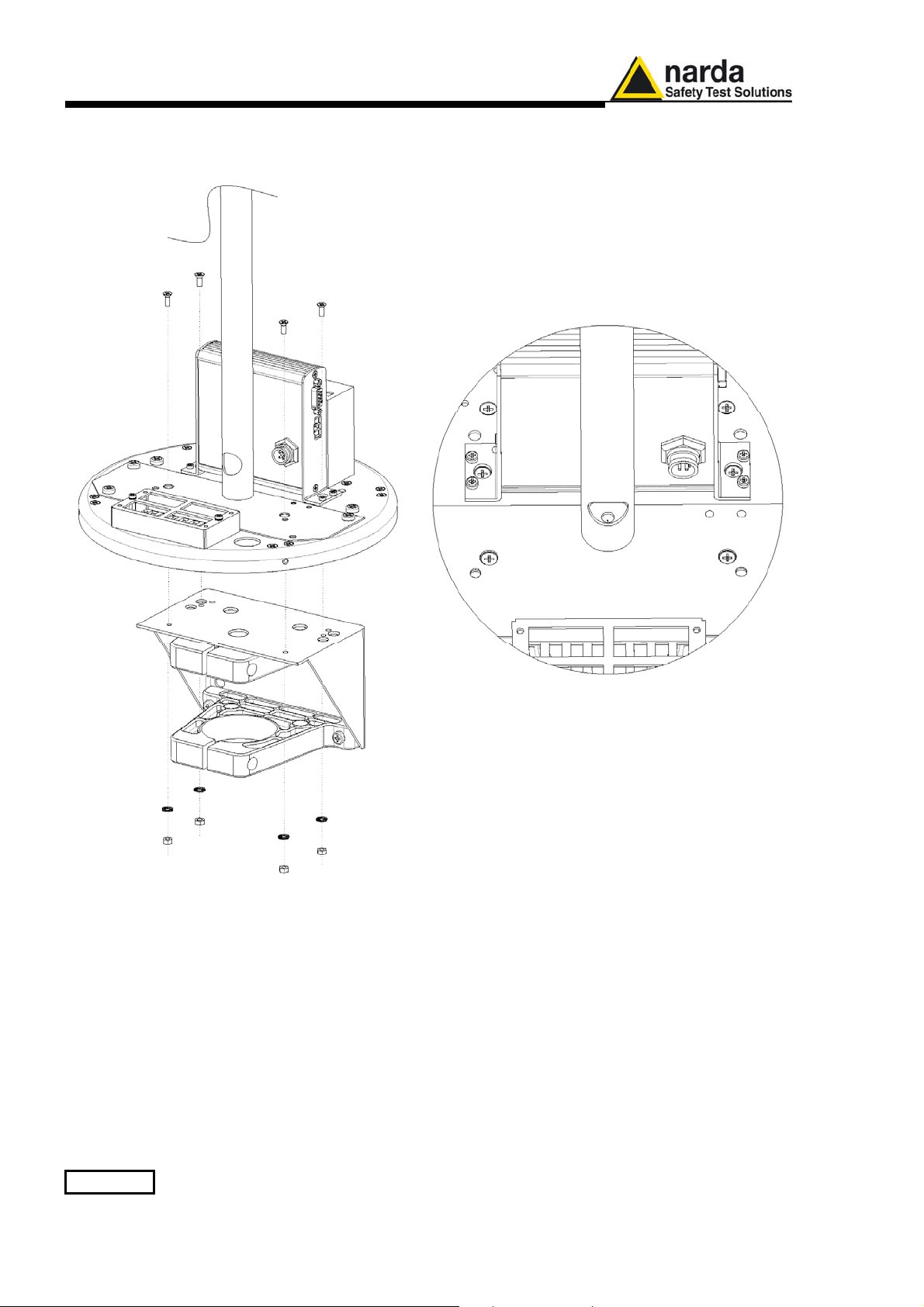
7. Remove the metallic bracket from the receiver baseplate unscrewing
the four countersunk screws, nut and washers.
5-4 AMS-8063/WMK Wall Mounting Kit
 Loading...