

Page 1

NARDA
Safety
Test
Solutions
S.r.l. Socio Unico
Sales & Support:
Via Leonardo da Vinci, 21/23
20090 Segrate (MI) -
ITALY
Tel.: +39 02 2699871
Fax: +39 02 26998700
Manufacturing Plant:
Via Benessea, 29/B
17035 Cisano sul Neva (SV)
Tel.: +39 0182 58641
Fax: +39 0182 586400
http://www.narda-sts.it
SERIAL NUMBER OF THE INSTRUMENT
You can find the serial number
on the upper cover of the receiver unit, on the
side of the receiver unit baseplate and on the side of the Power Pack.
Serial number is in the form: 000XY00000.
The first three digits and the two letters are the Serial Number prefix, the last five
digits are the Serial Number suffix. The prefix is the same for identical instruments,
it changes only when a configuration change is made to the instrument.
The suffix is different for each instrument.
Document AMS8061EN-81008-1.22 – Copyright © NARDA 2018
User’s Manual
AMS-8061
AREA MONITOR SELECTIVE
Page 2

II Note and symbols
NOTE:
® Names and Logo are registered trademarks of Narda Safety Test Solutions GmbH and L3 Communications
Holdings, Inc. – Trade names are trademarks of the owners.
If the instrument is used in any other way than as described in this User’s Manual, it
may become unsafe.
Before using this product, the related documentation must be read with great care and fully understood to familiarize
with all the safety prescriptions.
To ensure the correct use and the maximum safety level, the User shall know all the instructions and
recommendations contained in this document.
This product is a Safety Class III instrument according to IEC classification and has
been designed to meet the requirements of EN61010-1 (Safety Requirements for
Electrical Equipment for Measurement, Control and Laboratory Use).
In accordance with the IEC classification, the power supply of this product meets requirements Safety Class II and
Installation Category II (having double insulation and able to carry out mono-phase power supply operations).
It complies with the requirements of Pollution Class II (usually only non-conductive pollution). However,
occasionally it may become temporarily conductive due to condense on it.
The information contained in this document is subject to change without notice.
EXPLANATION OF ELECTRICAL AND SAFETY SYMBOLS :
You now own a high-quality instrument that will give you many years of reliable service.
Nevertheless, even this product will eventually become obsolete. When that time comes, please
remember that electronic equipment must be disposed of in accordance with local regulations.
This product conforms to the WEEE Directive of the European Union (2002/96/EC) and belongs to
Category 9 (Monitoring and Control Instruments). You can return the instrument to us free of
charge for proper environment friendly disposal. You can obtain further information from your
local Narda Sales Partner or by visiting our website at www.narda-sts.it .
Warning, danger of electric shock
Earth
Read carefully the Operating Manual and its
instructions, pay attention to the safety symbols
Unit Earth Connection
Earth Protection
Equipotential
KEY TO THE SYMBOLS USED IN THIS DOCUMENT:
The DANGER sign draws attention to a serious risk to a person’s safety, which, if
not avoided, will result in death or serious injury. All the precautions must be fully
understood and applied before proceeding.
The WARNING sign indicates a hazardous situation, which, if not avoided,
could result in death or serious injury. All the precautions must be fully
understood and applied before proceeding.
The CAUTION sign indicates a hazardous situation, which, if not avoided,
could result in minor or moderate injury.
The NOTICE sign draws attention to a potential risk of damage to the
apparatus or loss of data.
The NOTE sign draws attention to important information.
Page 3

Contents III
Contents
Page
Safety considerations and instructions ….............…….
EC Declaration of Conformity .........................….............
VIII
IX
1 General information Page
1.1 Documentation..............................................................
1.2 Introduction.....................................……………………..
1.3 Standard accessories..................................................
1.4 Main specifications.............................…......................
1.5 Max acquisition time……………………………………..
1.6 AMS-8061 receiver panel …………..….……………..
1-1
1-1
1-2
1-3
1-5
1-7
2 Installation and use Page
2.1 Introduction............................................................…...
2.2 Initial inspection.....................................................…...
2.3 Working environment..........................................…..…
2.4 Return for repairs...................................................…...
2.5 Cleaning..................................................................…..
2.6 Installation and use.…...............................…………….
2.6.1 Installation….....................................................….…
2.6.1.1 Supporto base, feet and pole……………………….
2.6.1.2 Solar panel……………………………………………
2.6.1.2.1 Solar panel mounting……………………………..
2.6.1.2.2 Installation steps….....................................….…
2.6.1.3 Install the Solar panel to the Support base……….
2.6.1.4 Solar panel wiring and fuse…..…………………….
2.6.1.5 Receiver unit mounting……………………………..
2.6.1.6 Triaxial antenna……………………………………..
2.6.1.7 Connectors…………………………………………..
2.6.1.8 SIM CARD and led modem status…………………
2.6.1.9 GSM Modem……..……………………………….….
2.6.1.10 Micro SD card and led status……………………..
2.6.1.11 Led ON in relation to the status of the monitoring
station………………………………………..…………………
2.6.1.12 Radome……………………………………………..
2.6.1.13 Interlock….....................................................…....
2.6.1.14 Bags…………………………………………………
2.6.2 Battery charging………………………………………..
2.6.3 External power supply…………..…………………….
2.7 How to switch the GSM modem on…………….………
2.8 Programmed mode………………………………………
2.9 Spontaneous mode………………………………………
2.10 Automatic mode………………………………………...
2.11Selective unit switching ON/OFF..…………………….
2.12 RF signals of dangerous intensity….......................…
2.13 Controlling the internal battery...................................
2.14 Suggestions and checking list to define Area monitor
problems………………………………….………..….
2-1
2-1
2-1
2-1
2-2
2-2
2-3
2-3
2-5
2-5
2-6
2-8
2-11
2-13
2-15
2-16
2-17
2-17
2-18
2-20
2-21
2-22
2-22
2-23
2-25
2-27
2-27
2-27
2-27
2-28
2-28
2-28
2-29
Page 4

IV Contents
3 GPRS and FPT Instructions
3.1 Introduction…………............................................…........
3.2 Structure ………………..............................................…..
3.3 Configuration (read) ………………………………………..
3.4 FLD File (Read) ……………………………………………..
3.5 Record File (Write) ………………………………………….
3.6 FLD File (Write) ……………………………………………..
3.7 Event File (Write) ……………………………………………
3.8 Setting Status (Write) ……………………………………...
3.9 GPRS – FTP Settings ……………………………………...
3.10 checksum algorithm ………………………………………
3.11 D61 Structure, Download description …………………..
3.11.1 Command Mode ………………………………………...
3.11.2 GPRS/FTP Mode ……………………………………….
3.11.3 Selective Multiband Structure description ……………
3.11.4 GPS Information ………………………………………..
3.11.5 Band Packet description ……………………………….
Page
3-1
3-2
3-3
3-6
3-7
3-7
3-7
3-8
3-12
3-14
3-15
3-15
3-15
3-16
3-20
3-23
4 SMS Messages and Commands Page
4.1 Introduction………………………………………..………..
4.2 Command list.................................................................
4.3 Query COMMANDs........................................................
4.4 Setting COMMANDs.......................................................
4.5 GPRS Connection Data……………………………………
4.6 FTP Connection Data………………………………………
4-1
4-2
4-5
4-13
4-20
4-21
5 Packaging Instructions Page
5.1 Introduction………………………..…………………..…....
5.2 Packaging Instructions………….............................…..…
5-1
5-1
6 Action of the wind on the AMS-8061 Page
6.1 Introduction………………………..…………………..…....
6.2 AMS-8061…………………….............................…..……
6-1
6-2
7 Instructions for use of the 8060-SW02 control software Page
7.1 Introduction…………...........................................…........
7.2 Hardware requirements.............................................…..
7.3 Installation of the software....................................….......
7.4 Starting the program.........................................…...........
7.4.1 Assigning the serial port………………………………....
7.4.1.1 Virtual COM port installation………………………….
7.4.2 Checking for the Modem……………….……….……….
7.4.3 Entering the terminal Password……………………..….
7.4.4 Changing a Password…………………………..…..……
7.4.5 Entering the setting Password………………………….
7.4.6 Main window……………………………….……………..
7.5 CSD mode…………………………………………………..
7.5.1 Alarm column…………………………………………….
7.5.2 Entering a new station……………………………………
7.5.3 Removing a station……………………………………….
7.5.4 Editing a station……………………………………………
7-1
7-2
7-4
7-8
7-9
7-10
7-11
7-16
7-18
7-19
7-20
7-21
7-25
7-26
7-27
7-27
Page 5

Contents V
7.5.5 Automatic data downloads…………………..…………..……..
7.5.6 Answering……………………………….….…….….…………..
7.5.7 Calling………………………………….…………….…………..
7.5.8 Auto ASCII File……………………….……………….….……..
7.5.9 Autoload events…………………….……….……….…..……..
7.5.10 Filling data…………………………………………….………..
7.5.11 Exporting data…………………………………………...……..
7.5.12 Direct readings…………………………………………..……..
7.5.13 Send settings…………………………………………….……..
7.5.14 Calendar of measurements…………………………………..
7.5.15 Calling a station via RS232 or USB…………………...……..
7.5.16 Calling a station via GSM modem (CSD modem)…… …..
7.5.17 Control window.......................................................….……..
7.5.17.1 Description of controls.........................................….……..
7.5.17.2 Alarm...................................................................…..……..
7.5.17.3 Notify alarms through………………………………………..
7.5.17.4 Last field………………………………….…………………..
7.5.17.5 Averaging Period………………………….…………..……..
7.5.17.6 Max Field ALARM Settings ………………………….……..
7.5.17.7 Battery section………………………………………………..
7.5.17.8 Probe section………………………………………….……..
7.5.17.9 Over heat……………………………………………………..
7.5.17.10 Relative humidity….………..………………………….…..
7.5.17.11 Case OPEN……..…………………………………………..
7.5.18 Schedule for modem…………………………………...……..
7.5.19 Schedule for SMS……………………………………….……..
7.5.20 Rate settings……………………………………………..……..
7.5.21 Get DATA………………………………………………..…..…..
7.5.22 Examples of errors……………..………………..……..……....
7.5.23 Updating Firmware.................….............................….……..
7.5.24 Station Date&Time……………………………………………..
7.5.25 General commands……………………………………..……..
7.5.26 Read Station Configuration……………………………..……..
7.5.27 Enable setting…………………………………………….……..
7.5.28 GPS……………………………………………………....……..
7.5.29 Hang and exit…………………………………………….……..
7.5.30 Sub bands………………………………………………..……..
7.5.31 Exit………………………………………………………..……..
7.5.32 Download data via serial port, RS232………………..……..
7.5.32.1 Possible errors………………………………………..……..
7.5.33 Software update………………………………………...……..
7.6 FTP mode…………………………………………………………..
7.6.1 GPRS/FTP introduction………………………………….……..
7.6.2 Brief description of GPRS communication…………….……..
7.6.3 Monitoring networks……………………………………………..
7.6.4 System operation in GPRS mode……………………….……..
7.6.5 Some advantages………………………………………………..
7.6.6. Remote station………………………………………………….
7.6.7 Minimum requirements of the controller PC…………............
7.6.8 FTP server requirements………………………………………..
7.6.9 Brief operating description and file structure………………….
7.6.10 Structure………………………………………………………...
7.6.10.1 CFG file (configuration)………………………………………
7.6.10.2 FLD file (Read)……………………………………………….
7.6.10.3 Record file (Write)……………………………………………
7.6.10.4 FLD file (Write)………………………………………………..
7.6.10.5 Event file (Write)………………………………………………
7.6.11 First installation and parameter setting………………………
7.6.12 FTP-GPRS commands…………………………………………
7.6.13 Additional tests and hints………………………………………
7.6.14 AMS-8061 Firmware updates………………………………….
7.6.15 Data download calculation and space occupied in the FTP
server…………………………………………………………………….
7.7 Uninstalling software………………………………………………
7-28
7-29
7-30
7-30
7-31
7-31
7-33
7-34
7-35
7-36
7-38
7-39
7-41
7-42
7-45
7-45
7-46
7-46
7-47
7-48
7-48
7-49
7-49
7-49
7-50
7-51
7-52
7-54
7-56
7-59
7-61
7-62
7-62
7-62
7-62
7-62
7-63
7-66
7-67
7-67
7-68
7-69
7-69
7-70
7-70
7-70
7-71
7-72
7-72
7-73
7-73
7-73
7-73
7-74
7-74
7-74
7-75
7-75
7-96
7-96
7-97
7-97
7-98
Page 6

VI Contents
8 Data presentation Page
8.1 Introduction......…...............................…….....................
8.2 The Calendar..............................................…................
8.3 Data window..................................................…........…..
8.4 Main commands.....................................…..…..……......
8.4.1 File…………………………………………………...…...
8.4.2 Option…………………………………………...………..
8.4.3 Trace…………………………………………………….
8.4.4 Marker……………………………………………..……..
8.4.5 Vertical…………………………....………………..…….
8.5 Secondary commands……..………………………..……
8.5.1 Save Files……………………………………………......
8.5.1.1 Save File in ASCII format………………………….....
8.5.2 Open Files………………………………………………..
8.5.2.1 Open Autotext file……………………………………..
8.5.3 Show table file……………………………………………
8.5.4 Clipboard…………………………………………………
8.5.5 Zoom mode………………………………………………
8.5.6 Comment…………………………………………………
8.5.7 Redraw……………………………………………………
8.5.8 Appearance………………………………………………
8.5.9 Setup……………………………………………………...
8.5.9.1 Setup……………………………………………………
8.5.10 Limit……………………………………………………..
8.5.10.1 SCREEN sample…………………………………….
8.5.11 Software release……………………………………….
8.6 Graph window……………………………………………...
8.7. Status window……………………………………………..
8.8 Importing data to Word or Excel…………………………
8-1
8-1
8-2
8-4
8-4
8-4
8-5
8-6
8-7
8-8
8-8
8-9
8-10
8-12
8-14
8-14
8-15
8-15
8-16
8-16
8-17
8-17
8-18
8-18
8-18
8-18
8-19
8-19
9 Service Page
9.1 Air filters replacement.........................……......................
9.1.1 Introduction...............................................….................
9.1.2 Receiver unit filter and baseplate filter replacement…..
9-1
9-1
9-2
Page 7

Contents VII
Figures
Figure Page
1-1
1-2
1-3
1-4
2-1
2-2
2-3
2-4
6-1
6-2
7-1
7-2
9-1
AMS-8061 Field Monitoring System…………………….
EHA-2B-01 Antenna……..…………………………………
AMS-8061 receiver unit panel…………………………….
AMS-8061 Receiver unit panel……………………………
AMS-8061 Field Monitoring System ..……………………
DB9 Female front side view……………………………….
Slot for the SIM card………………………….…………….
Slot for the Micro SD card………………………………….
AMS-8061 Field Monitoring System……………………..
Weight Ballast variation in comparison to the wind
speed for AMS-8061……………………………………….
FTP Main window ………………………………………….
Setting window ……………………………………...……..
Air filters replacement……………………………………..
1-1
1-6
1-6
1-7
2-2
2-16
2-17
2-18
6-1
6-3
7-77
7-82
9-2
Tables
Table Page
1-1 Technical specifications of AMS-8061….…….............. 1-3
1-2
1-3
2-1
2-2
2-3
6-1
Settings/Queries of the AMS-8061…........……............
Antennas Specifications ………………………………….
Led Ethernet status………………………………….........
Led Modem status………………………………………….
Led Micro SD card status………………………………….
Wind resistance of the AMS-8061……………………….
1-5
1-5
2-16
2-17
2-19
6-2
Page 8

VIII EC Conformity
SAFETY RECOMMENDATIONS AND INSTRUCTIONS
This product has been designed, produced and tested in Italy, and it left the factory in conditions fully
complying with the current safety standards. To maintain it in safe conditions and ensure correct use,
these general instructions must be fully understood and applied before the product is used.
• When the device must be connected permanently, first provide effective grounding;
• If the device must be connected to other equipment or accessories, make sure they are all safely
grounded;
• In case of devices permanently connected to the power supply, and lacking any fuses or other
devices of mains protection, the power line must be equipped with adequate protection
commensurate to the consumption of all the devices connected to it;
• In case of connection of the device to the power mains, make sure before connection that the
voltage selected on the voltage switch and the fuses are adequate for the voltage of the actual
mains;
• Devices in Safety Class I, equipped with connection to the power mains by means of cord and plug,
can only be plugged into a socket equipped with a ground wire;
• Any interruption or loosening of the ground wire or of a connecting power cable, inside or outside the
device, will cause a potential risk for the safety of the personnel;
• Ground connections must not be interrupted intentionally;
• To prevent the possible danger of electrocution, do not remove any covers, panels or guards
installed on the device, and refer only to NARDA Service Centers if maintenance should be
necessary;
• To maintain adequate protection from fire hazards, replace fuses only with others of the same type
and rating;
• Follow the safety regulations and any additional instructions in this manual to prevent accidents and
damages.
Page 9

Safety Considerations IX
Dichiarazione di Conformità
EU Declaration of Conformity
In accordo alla Decisione 768/2008/EC, conforme alle direttive EMC 2014/30/UE, Bassa Tensione 2014/35/UE e
RoHS 2011/65/UE, ed anche alle norme ISO/IEC 17050-1 e 17050-2.
In accordance with the Decision 768/2008/EC, compliant to the Directives EMC 2014/30/EU, Low Voltage 2014/35/EU and
RoHS 2011/65/EU, also compliant to the ISO/IEC standard 17050-1 and 17050-2
Il costruttore
The manufacturer
narda Safety Test Solutions S.r.l. Socio Unico
Indirizzo
Address
Via Benessea, 29 / B
I-17035 Cisano sul Neva (SV) - Italy
sulla base delle seguenti norme europee armonizzate, applicate con esito positivo:
based on the following harmonized European Standards, successfully applied:
EMC - Emissioni:
EMC - Emission:
EN 61326-1 (2013)
EMC - Immunità:
EMC - Immunity:
EN 61326-1 (2013)
Sicurezza:
Safety:
EN 61010-1 (2010)
dichiara, sotto la propria responsabilità, che il prodotto:
declares, under its sole responsibility, that the product:
Descrizione
Description
STAZIONE DI MONITORAGGIO SELETTIVA
AREA MONITOR SELECTIVE
Modello
Model
AMS-8061
è conforme ai requisiti essenziali delle seguenti Direttive:
conforms with the essential requirements of the following Directives:
Bassa Tensione
Low Voltage
2014/35/EU
Compatibiltà Elettromagnetica
EMC
2014/30/EU
RoHS
RoHS
2011/65/EU
Cisano sul Neva, 06 June 2017
Egon Stocca
General Manager
Page 10

X EC Conformity
This page has been left blank intentionally
Page 11

General Information 1-1
1 – General information
1.1 Documentation
This Users Manual contains the following annexes:
• A form to return to NARDA with the device when requesting service.
• A checklist of the parts included in the shipment.
This Users Manual also includes the description of the accessories of the
system for distributed frequency selective monitoring of environmental
electromagnetic fields.
1.2 Introduction
The AMS-8061 system is a revolutionary, accurate and reliable solution for
remote and continuous monitoring of electromagnetic fields both in
broadband and in frequency selective mode.
The AMS-8061 system includes an accurate and sensitive receiver which,
being equipped with the proper filters and coupled to the specific
broadband, omni-directional antennas, make it possible to measure the
contribution to the total field of all the user definable frequency bands.
All commands are available to program any relevant parameter including
automatic download of measurement results to the User’s FTP server by
means of GPRS remote communication.
In the event of any alarm, such as a threshold setting being exceeded, or
any attempt to tamper with the remote unit, or a breakdown of the unit, it is
possible to receive on any mobile phone an SMS informing the user of the
event.
Fig. 1-1 AMS-8061 Field Monitoring System
AMS-8061 unit is equipped with solar panel (twin pair) and high capacity
back-up batteries. An external power supply is provided for continuous,
indoor operation.
Document AMS8061EN-81008 -1.22 - © NARDA 2018
Page 12

1-2 General Information
1.3 Standard accessories
The monitoring station is composed by a main measuring/processing unit,
GSM modem with GPS module and antenna system. An RF transparent
radome protects the station from the weather. The measuring unit comes
ready to be mounted on its pole and connected to the power pack.
The standard solar panel has to be mounted on the support base.
For remote communication it is essential to equip the unit with a SIM
card that must be enabled for the selected data communication
(GPRS/FTP, CSD or both).
Standard accessories included with the 8061 unit are:
• AC/DC power supply/battery charger
• USB cable
• Ethernet cable
• Ballast bags
• Tools kit
• Certificate of calibration
• Software Installer and Manual on Software Media
• Operating Manual
• Return for Repair form
Page 13

General Information 1-3
1.4 Main Specifications
Tables 1-1 – 1-2 list the specifications of AMS-8061.
TABLE 1-1 Technical Specifications of AMS-8061
Frequency range 100 kHz – 6 GHz
(in accordance with antenna specifications)
User-Programmable frequency bands Up to 20, individual start-stop frequency settings
Sensor type Triaxial, isotropic antenna system
Sensor dimensions (Ø) 120 mm
Sensor RF connection 50 Ohm, N-male
Sensor control Multi-pin connector
Dynamic range > 60 dB in all settings of the attenuator
Measurement range
Sensitivity
Overload
Resolution Depending on the antenna
Linearity (please refer to the antenna specifications pag.1-5)
Frequency response (flatness)
Overall anisotropy (EN50383)
Unit
Out of band attenuation >50 dB, depending on settings
Rejection > 20 dB
Calibration Performed in EA accredited laboratory: Accredia LAT nr.008
Calibration interval 2 years (recommended)
Reading rate Down to 200 ms (depending on the band setting)
Measuring parameters Settable bands and automatic configuration
EMF stored values AVG or RMS, Max value
Average Arithmetic (AVG) or RMS
Average time 1 – 15 minutes
Storing rate 1, 2, 6, 15 minutes
Max. logging before overwriting 18 months @ 6 minutes storing rate
3 months @ 1 minute storing rate.
Alarms SMS and/or data download for: field over limit, open case,
temperature, humidity, low battery, sensor failure.
Page 14

1-4 General Information
Communication FTP and CSD protocols via internal GSM/GPRS modem, Ethernet, RS-232 and
USB link.
Data download FTP: automatic to server; CSD: automatic or manual to PC
SIM card type (not included) Enabled for selected data transmission
SMS SMS to 10 mobile phones (daily report of max. EMF value, battery voltage)
Battery management Every record includes Battery Voltage and Charge Current value
Temperature and humidity sensors Internal, logged in memory
GPS coordinates Latitude, longitude
Clock Internal real time clock
Firmware upgrade Remotely upgradable (FTP, CSD, Ethernet, RS-232 and USB)
Interface RS-232, Ethernet and USB
External memory Micro SD card (not included)
Power supply Solar panel 17.5 V, 2 x 40 W
Backup sealed Pb rechargeable battery, 12 V
External DC 12 V – 3 A
AC power supply and battery charger 100…240 V, 50/60 Hz to 24 VDC, 1.25A
Autonomy with battery only 48 to 60 Hours, setting depending
Autonomy with Solar panel 24 hours/365 days for PSH (Peak Sun Hours) ≥ 2; equal to ≥2 kWh/m
2
per day
Operating temperature -10 °C to 55 °C
Humidity ≤ 95%
Wind speed Max. 150 km/h (unit must be installed according to instructions)
Protection grade IP55
Overall dimensions (LxHxD) 1480x1100x715 mm
Radome dimension (Ø x H) 250 x 740 mm
Pole dimension (Ø x H) 60 x 760 mm
Base dimension (LxHxD) 660 x 95 x 600 mm
Solar panel dimension (LxHxD) 1100 x 610 x 35 mm
Weight: Approx. Approx. 34 kg
Page 15

General Information 1-5
1.5 Max acquisition time
The device can measure and save data for a long period of time. The total
time depends on the storing rate, number of frequency bands.
The internal memory can be read at every new data transfer to the central
unit, at set times or by remote control. Moreover, when the memory is full,
the new data are overwritten on the oldest to ensure availability of the data
for the most recent measurement period.
Settings can be made and the devices can be queried via SMS, serial
connection, Ethernet, GSM or line modem, FTP communication through
FTP server. The following table describes the different possibilities.
TABLE 1-2 Settings/Queries of the AMS-8061
Possible functions SMS 8061 via Modem 8061 via RS-232
Settings
Reading status and alarms
Reading max value
Reading average value
Download data
Reading of battery
Reading of internal temperature
Spontaneous call
Reporting alarms
Reporting via SMS of daily maximum
YES
YES
YES
YES
NO
YES
YES
NO
YES
YES
YES
YES
YES
YES
YES
YES
YES
YES
YES
NO
YES
YES
YES
YES
YES
YES
YES
NO
NO
NO
TABLE 1-3 Antennas Specifications
Model EHA-2B-01 HA-1B-01 EA-1B-01 EA-1B-02
Frequency range
100 kHz – 6 GHz 100 kHz – 110 MHz 110 MHz – 6 GHz 27 MHz – 3 GHz
Measurement range
0.01 – 160 V/m 100 µA/m ÷ 7 A/m 0.01 – 160 V/m 0.01 – 200 V/m
Sensitivity
0.01 V/m
100 µA/m 0.01 V/m 0.01 V/m
Overload
435 V/m 20 A/m 435 V/m 435 V/m
Resolution
0.01 V/m 100 µA/m 0.01 V/m 0.01 V/m
Linearity
≤ ± 2 dB ≤ ± 2 dB ≤ ± 2 dB ≤ ± 2 dB
Frequency response (flatness)
≤ ± 3 dB ≤ ± 3 dB ≤ ± 3 dB ≤ ± 3 dB
Overall anisotropy (EN50383)
<2.5 dB up to 3 GHz
<3.5 dB up to 6 GHz
<2.0 dB <2.5 dB up to 3 GHz
<3.5 dB up to 6 GHz
<2.5 dB
Unit
V/m A/m V/m V/m
Page 16

1-6 General Information
The AMS-8061 system is equipped with mod. EHA-2B-01 antenna.
Fig. 1-2 EHA-2B-01 Antenna
The EHA-2B-01 triaxial antenna includes a triaxial magnetic field
sensor. Computation of electric field, expressed in V/m by the
station, is done assuming the measurement is taken in far field
condition where the known ratio between magnetic and electric field
allows good correlation accuracy.
Operator should check distance from field sources to evaluate
reliability.
Fig. 1-3 EA Antenna models
Page 17

General Information 1-7
1.6 AMS-8061
receiver
panel
Fig. 1-4 AMS-8061 receiver unit panel
Legend:
1) GSM antenna
2) SIM card slot
3) GPS antenna
4A) Status LEDs
4B) Controller LEDs
5) RS232 serial interface connector
6) Power switch
7) Power supply connector
8) RF input N connector
9) Antenna data and power supply connector
10) Reserved
11) Micro-SD card slot
12) Ethernet RJ45 LAN connector
13) USB connector
14) Service 2.5mm-jack connector
Page 18

1-8 General Information
This page has been left blank intentionally
Page 19

Installation and use 2-1
2 – Installation and use
2.1 Introduction
This section provides the information necessary to install and use the
AMS-8061 Field Monitoring System.
It also includes information regarding initial inspection, power
requirements, interconnections, working environment, assembly, cleaning,
storage and shipment.
2.2 Initial inspection
Inspect the package for any possible damage.
If the packaging or protective material are damaged, check that the
content is complete and that the instrument has not been damaged in
any of its electrical or mechanical parts. Check the accessories,
referring to the checklist enclosed with the manual. Report any
noticed damage to the forwarder and to NARDA.
2.3 Working environment
The working conditions for the instrument are as follows:
• Temperature
• Relative humidity
From -10°C to +55°C
≤ 95%
The instrument should be stored in a clean, dry place free of acids, dust
and moisture.
The storage environment must have the following specifications:
• Temperature
• Relative humidity
From -20°C to + 70°C
< 99%
• Altitude
Up to 4000 m (a.s.l.)
2.4 Return for repairs
Any part of the instrument – with the sole exception of the air filters (see
Service chapter) - can only be replaced by NARDA, therefore, in case of
damage to parts and/or malfunctions, contact the NARDA service center.
When the instrument has to be returned to NARDA for repairs, please
complete the form included in this User’s Manual, filling in all the
information necessary for the service requested.
To reduce the time necessary for the repair, be as specific as possible in
describing the malfunction. If the problem only occurs under specific
conditions, detail in the best possible way how to reproduce these
conditions.
Whenever possible, it is preferable to use the original packing for return,
making sure to wrap the device in heavy paper or plastic (see section 6 for
detailed packaging instructions). In alternative, pack the equipment in a
sturdy cardbox with plenty of impact absorbing material all around the
equipment, to ensure a tight fit and prevent it from moving inside the box.
Take special precautions to protect the solar cells and GSM modem
antenna. Seal the package securely and write FRAGILE on the outside to
encourage careful handling.
Nowadays there are restrictions on the shipment of hazardous
materials, eg. some types of lithium batteries.
Please, check the proper, safe, shipping mode, with the help of your
courier, in the case the product is equipped with batteries.
Document AMS8061EN-81008 -1.22 - © NARDA 2018
Page 20

2-2 Installation and use
2.5 Cleaning
Use a clean, soft, dry cloth to clean the instrument and the solar cells.
To clean the instrument do not use solvents, acids, cleaning fluid,
turpentine, acetone or similar products which could damage it.
It is suggested to replace air filter at least once a year or more
frequently if needed.
2.6 Installation
and use
The AMS-8061 Field Monitoring System consist of a vertical housing with
circular shape made of material that is transparent to electromagnetic
fields. Within this radome is housed the measuring device, as well as the
measuring antenna and the remote communication device.
Batteries are located within the power pack on the support base.
AMS-8061 power system includes high quality lead batteries which
provide very good performance even in the voltage, current and
temperature most severe condition. Nevertheless, as happens in all
lead accumulators, capacity is influenced by temperature. Best
performance are achieved around 20°C.
Fig. 2-1 AMS-8061 Field Monitoring System
Page 21

Installation and use 2-3
2.6.1 Installation
The AMS-8061 Field Monitor is designed to operate outdoors, in the
vicinity of the electromagnetic fields sources that shall be controlled, and
under the most severe environmental conditions.
2.6.1.1 Support base,
feet
and pole
Install the Support base on the site to be monitored
Before proceeding to permanent installation, make sure that the point
at which the field monitor will be installed is adequately covered by
the mobile phone service used for the GSM modem.
This can be done using any GSM mobile phone capable of indicating
the intensity of the signal coming from the local base radio station of
the company chosen for the SIM card.
Correct readings may be conditioned by the nature of the places in
which the AMS-8061 Field Monitoring System is installed.
The field measuring antenna is affected by huge metallic masses or
other objects that may reflect the signal, if located in the vicinity of
the unit.
Whenever possible, it is a good rule to install the unit at some
distance from walls, high voltage pylons, buildings and other
obstacles that could affect the signals reaching the sensor.
Screw the four adjustable feet under the support base.
Page 22

2-4 Installation and use
Remove the bolt from the pole support, place the pole and fasten it to the
base using the bolt with nut and washers.
Using the supplied pole, whose characteristics have been carefully
assessed, is recommended to avoid any alteration of the field to be
monitored.
Page 23

Installation and use 2-5
2.6.1.2 Solar panel
2.6.1.2.1 Solar panel
mounting kit
The accessories included are:
1) 40W Solar panel (2 pcs);
2) Hexagon head bolt M4x10mm (4 pcs.);
3) Upper L shaped bracket (1 pc.);
4) Tooth washer Ø4mm (4 pcs.);
5) M4 nut (4 pcs.);
6) M5 nut (2 pcs.);
7) Tooth washer Ø5mm (2 pcs.);
8) M5 nut (2 pcs.);
9) Tooth washer Ø5mm (2 pcs.);
10) S shaped bracket (1 pc.);
11) Pan head machine screw X shaped M5x10mm (2 pcs.);
12) PA6 black bracket (1 pc.);
13) Pan head machine screw X shaped M5x25mm (2 pcs.);
14) Hexagon head bolt M4x10mm (2 pcs.);
15) Hexagon head bolt M8x12mm (2 pcs.);
16) Pan head machine screw X shaped M4x16mm (2 pcs.);
17) 55deg lower support (1 pc.);
18) M8 nut (2 pcs.);
19) Tooth washer Ø4mm (2 pcs.);
20) Tooth washer Ø4mm (2 pcs.);
21) M4 nut (2 pcs.);
22) M4 nut (2 pcs.);
- 13mm combination wrench;
- 7mm combination wrench;
- Reversible screwdriver.
Page 24

2-6 Installation and use
2.6.1.2.2 Installation
Steps
Upper L shaped bracket
S shaped bracket and PA6 black bracket
55deg lower support
Page 25

Installation and use 2-7
Page 26

2-8 Installation and use
2.6.1.3 Install the Solar
panel to the
Support base
Unscrew the Pan head screw inside the PA6 black bracket without losing it
completely.
Insert and slide the Solar panel into the fiberglass pole and position the
55deg lower support on the base
Position the Solar panel and the Support base on the ground as shown
and install the 55deg lower support.
Page 27

Installation and use 2-9
Install the 55deg lower support to the support base with the 2 pcs. Pan
head machine screw X shaped M4x16mm (16), 2 pcs. Tooth washer
Ø4mm (20) and 2 pcs M4 nut (22) remaining.
Position the Solar panel and the Support base on the ground as shown
below.
In the northern (boreal) hemisphere, the AMS-8061 should be
installed with the solar cells facing south, in order to take the best
advantage of the solar radiation for continuous recharging of the
internal batteries. An angle of 35° with respect to vertical is the ideal
position for the solar cells to optimize solar radiation in the European
latitudes, specially in winter when the light levels are generally lower
than in summer.
To ensure maximum efficiency in recharging the battery and to take
advantage of the maximum operating autonomy, make sure the
position in which the unit is installed receives sunlight all the day
long and is not shaded by buildings or other screening objects.
Page 28

2-10 Installation and use
To ensure maximum efficiency of recharging and optimum autonomy
of the internal batteries, it is a good rule to keep the solar cells of the
AMS-8061 clean, inspecting them periodically.
If necessary, clean them with a soft cloth and a normal glass
cleanser.
Fasten the Solar panel by tightening the bracket screws
Page 29

Installation and use 2-11
2.6.1.4 Solar panel wiring
and fuse
Remove the Power Pack cover
Remove the nut from the chock of the solar panel cable.
Page 30

2-12 Installation and use
Thread the cable through the hole in the box and screw the nut to fasten
the chock to the Power Pack.
Place the fuse.
Plug the solar panel connector.
Close the Power Pack box.
Page 31
Installation and use 2-13
2.6.1.5 Receiver unit
mounting
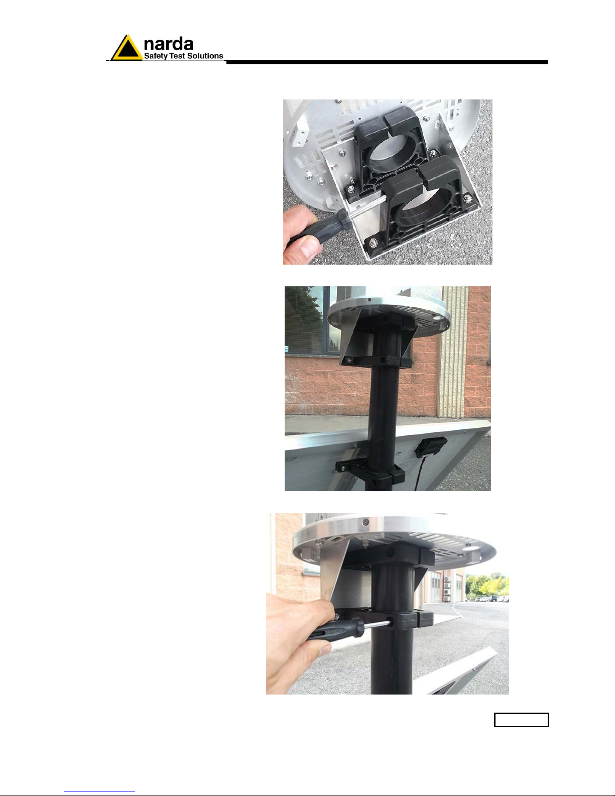
Before mounting the receiver unit on the pole, unscrew the Pan head screw
inside the both PA6 black brackets without losing it completely.
Mount the receiver unit on the pole.
Fasten the unit by tightening the bracket screws
Page 32
2-14 Installation and use
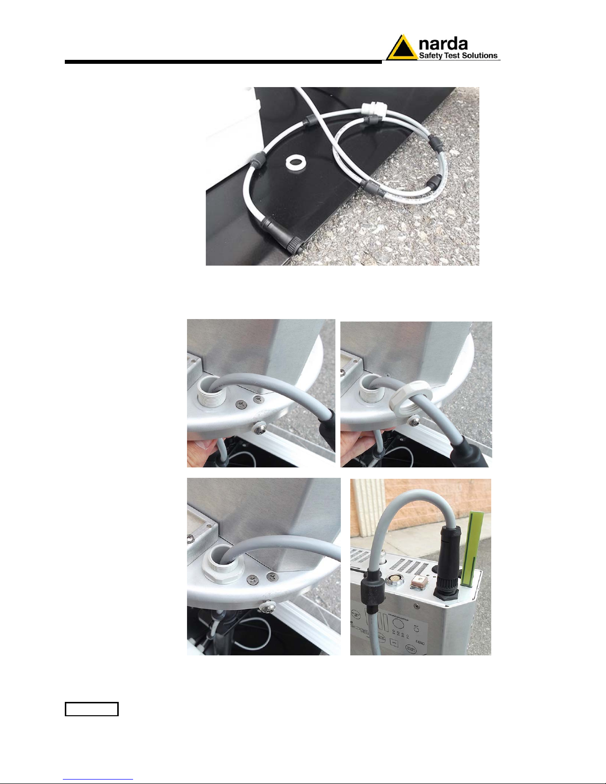
Remove the nut from the chock of the power cable.
Install the power cable by mounting the chock in the hole of the receiver
baseplate; plug the power supply connector to the receiver unit holding
by the plastic part.
Page 33

Installation and use 2-15
2.6.1.6 Triaxial antenna
Carefully connect the antenna output to the receiver RF input and plug the
antenna data connector looking at the alignment of the two red spot on the
data connectors.
To remove the antenna, extract the multipolar connector first holding
it by the metallic part, then turn the RF connector ring nut.
Do not insert or remove the antenna holding it by the head or by the
data cable as serious damage may occur.
The AMS-8061 station cannot operate without antenna even when
downloading acquired field data.
In case the antenna is accidentally removed when station is ON a
reset will be required: switch the station OFF, connect the triaxial
antenna and switch ON again.
Page 34
2-16 Installation and use
2.6.1.7 Connectors
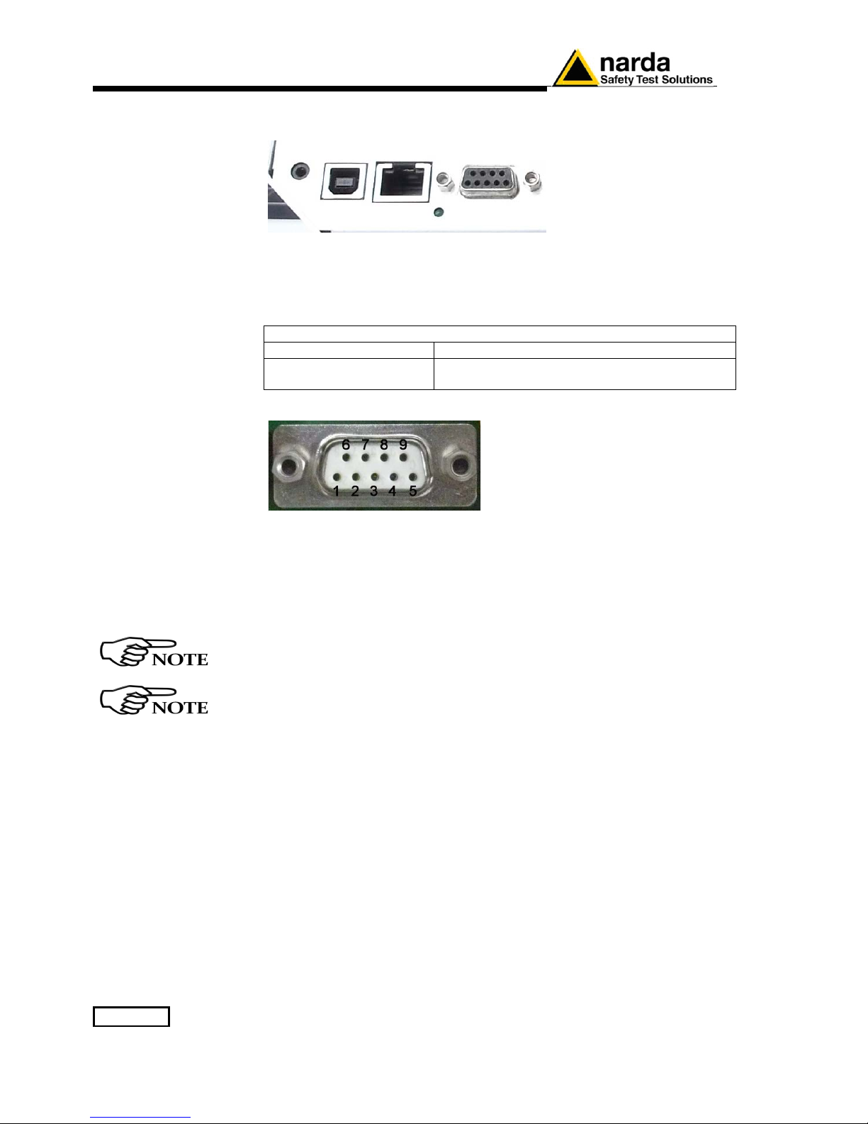
The AMS-8061 has an USB, Ethernet and RS-232 port for direct
connection to Personal Computer.
• USB connector for direct connection to Personal Computer.
• Ethernet connector and its led for direct connection to Personal
Computer.
TABLE 2-1 Led Ethernet status
LED Status Action
Steady GREEN
Ethernet cable is connected
• RS232 connector for direct connection to Personal Computer.
Fig. 2-2 DB9 Female front side view
DB9 Female Connector pin configuration:
Pin 2 RX [Received Data]
Pin 3 TX [Transmit Data]
Pin 5 GND [Signal Ground]
Pin 9 +3VD [Current limited]
When the Ethernet cable is connected to the AMS module, and it is
switched on, the RS232 port is not available.
Every time the Ethernet cable is plugged into the AMS module, the
connection will last 15 minutes regardless the scheduled time which
continues to work in separate way.
Page 35
Installation and use 2-17
2.6.1.8 SIM CARD and
led modem status
The SIM Card to be used must permit the transmission and reception of
data calls.
The user can choose the most suitable SIM Card to install, depending on
the services and costs offered by the different mobile phone Service
Providers; it should also be chosen so as to guarantee optimum coverage
for the specific zone of installation of the field monitor.
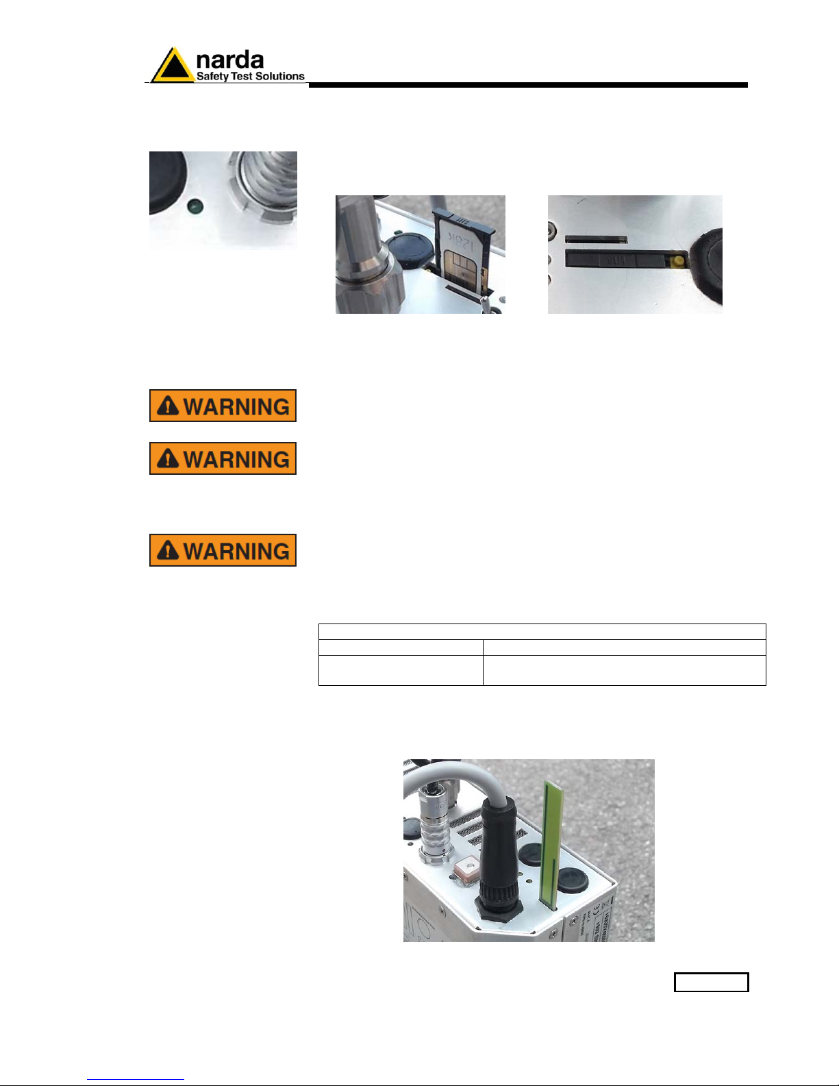
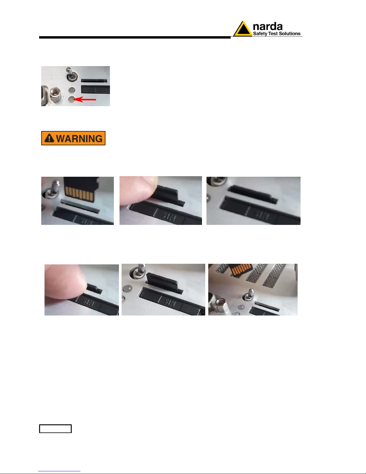
Fig. 2-3 Slot for the SIM card
The modem for data transfer is housed inside the receiver module; the SIM
Card has to be inserted in the slot shown in the figure (press the button to
remove the SIM card).
Before removing or inserting the SIM Card, switch off the
AMS-8061.
If you use a rechargeable SIM Card, make sure it is charged.
Before using the SIM Card with the AMS-8061, disable the PIN code
using the proper function available on any mobile phone.
The SIM card adopted shall be enabled to data transmission.
Dial up calls require that both the station SIM card as well as the PC
modem one (if GSM) are enabled for CSD data communication.
GPRS/FTP communication mode require that the station SIM card is
enabled for GPRS data communication allowing the station to access
the user FTP server to download measurement results, automatically,
according to the user setting. No modem but Internet access is
required for the controller PC to access the user FTP server
TABLE 2-2 Led Modem status
LEDs Status Action
Steady GREEN
Modem ON
2.6.1.9 GSM Modem
The AMS-8061 station is supplied with a GSM modem and antenna which
allows it to communicate with the controller PC for programming and for
the remote collection of the data recorded. To function properly, the GSM
modem requires a regular SIM Card enabled for data communication.
Page 36
2-18 Installation and use
2.6.1.10 Micro SD card
and led status
The AMS-8061 is a self-contained instrument which does not require any
external device such as mass-storage memory. Indeed, its built-in memory
is large enough to store data for a year and a half or longer than three
months with a rate of 1 minute.
However, the AMS-8061 supports Micro SD Cards. It is solely intended for
backing up data when no other way is accessible among the many present
(RS232, USB, FTP, Ethernet and MODEM-CSD).
Therefore, for no reason should an Micro SD Card be left in the slot
permanently, or for a long time, as its power consumption would
drastically reduce the autonomy with no advantage at all.
Moreover, GPS shares the same Micro SD Card port thus, when an Micro
SD Card is present, the GPS is disabled.
Before removing or inserting the Micro SD card, switch off the
AMS-8061.
To install the Micro SD Card:
- Slide the card into the slot
- Use your finger to gently push the card in until it stops and clicks into
place.
Fig. 2-4 Slot for the Micro SD card
To remove the Micro SD Card:
- Use your finger to gently push the card in until it stops and clicks into
place.
- Remove the card from the slot
In order to be used, an Micro SD Card should be first formatted, either FAT
or FAT32, and then have a file named "SD8061.SD1"in the root .
The size of this file, "SD8061.SD1", determines the number of record will
be backed-up on the Micro SD card.
According to the § 3.11 “D61 Structure, Download description”, each
record takes 352 bytes. Thus to store N records the required size is 352 x
N Bytes. For example, to back up 1000 records it is necessary to make the
file "SDCOPY.SD9" whose size is 352000 bytes.
The AMS 8061, as soon as it detects the presence of an Micro SD Card,
tries to open the file "SD8061.SD1" and, if successful, tries writing the last
<size_of_file> divided by 352 records having thus the most recent ones. In
the above example it would write the most recent 1000 records.
It is important to keep in mind that records will be aligned to last recordmost recent record.
Page 37
Installation and use 2-19
The Led let the user know about the state of process as shown in the
following table.
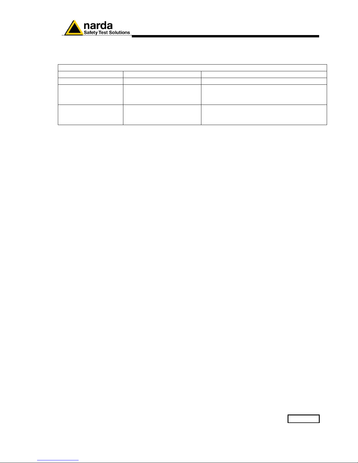
TABLE 2-3 Led Micro SD card status
LEDs Status Action
Blinking RED DATA is being storing
*** DO NOT REMOVE the SD Card ***
Steady RED SD Card ERROR This can be caused by:
• SD-card not formatted FAT or FAT32
• Damaged SD-Card
Steady ORANGE SD Card ERROR This can be caused by:
• File "SD8061.SD1" not present.
• Non-Writable SD-Card
Keep in mind that when storing all tasks are suspended thus it is better to
limit the size to the minimum required to avoid missing data.
Once more, do not leave the SD-Card in the slot as it would not store
anything more, as the storing process is triggered only by SD-Card
insertion. Instead, it would stop GSP activity and draw energy reducing
thus the autonomy.
Page 38
2-20 Installation and use
2.6.1.11 Led ON
in relation to the
status of the
monitoring station
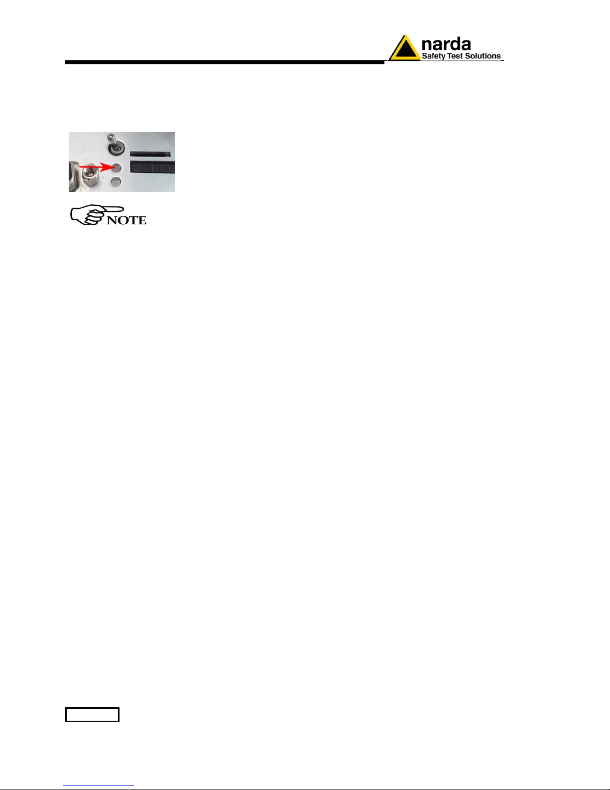
When the monitoring station is switched on, the Led ON is first lit with a
steady light for about 5 seconds, then starts to blink at the rate of one blink
per second, indicating that the monitoring station is active in normal StandBy conditions and not in the low consumption mode.
The condition in which the LED blinks at a rate of one (brief) flash per
second indicating that the monitoring station is in Stand-By mode and not
in low consumption mode, are the following:
• All the time the Modem is on Stand-By
Even if the user will disable most of the modem functions
through the software, the minimum periods at which the
internal modem would be ON (first hour after switch ON
without Low Battery alarm and from 11:00 to 11:45 when the
“Schedule for modem” and “Schedule for SMS” are set to
zero) the LED will be blinking every second
• The time between acknowledgment of a command (via RS232,
USB, Ethernet) to about 60 seconds from the last command
received.
• All the time between the attempts by the monitoring station to
establish a communication with the antenna to about 60 seconds
after correct acknowledgement of the connection.
After exiting this mode, the LED changes the manner of blinking to a (brief)
flash every three seconds, thus indicating the low consumption status. The
monitoring station remains in this status until an event rouses it and causes
the return to Stand-by status again.
Possible events are:
• Modem switched on in Programmed or Spontaneous mode
• Sending of a programmed or spontaneous SMS
• Activity on the RS232, USB, Ethernet.
As indicated above, about 60 seconds after the termination of the event,
the LED resumes blinking at the frequency of 0,3 Hz.
The LED also has five additional statuses:
• It blinks at a higher frequency than once per second during a
communication (from the beginning to the end) to indicate the
modem is in use.
• It remains on with fixed light during data downloads.
• It blinks red when the modem is on
• It blinks green when the modem is off
• It blinks orange when the Ethernet is connected
Page 39
Installation and use 2-21
2.6.1.12 Radome
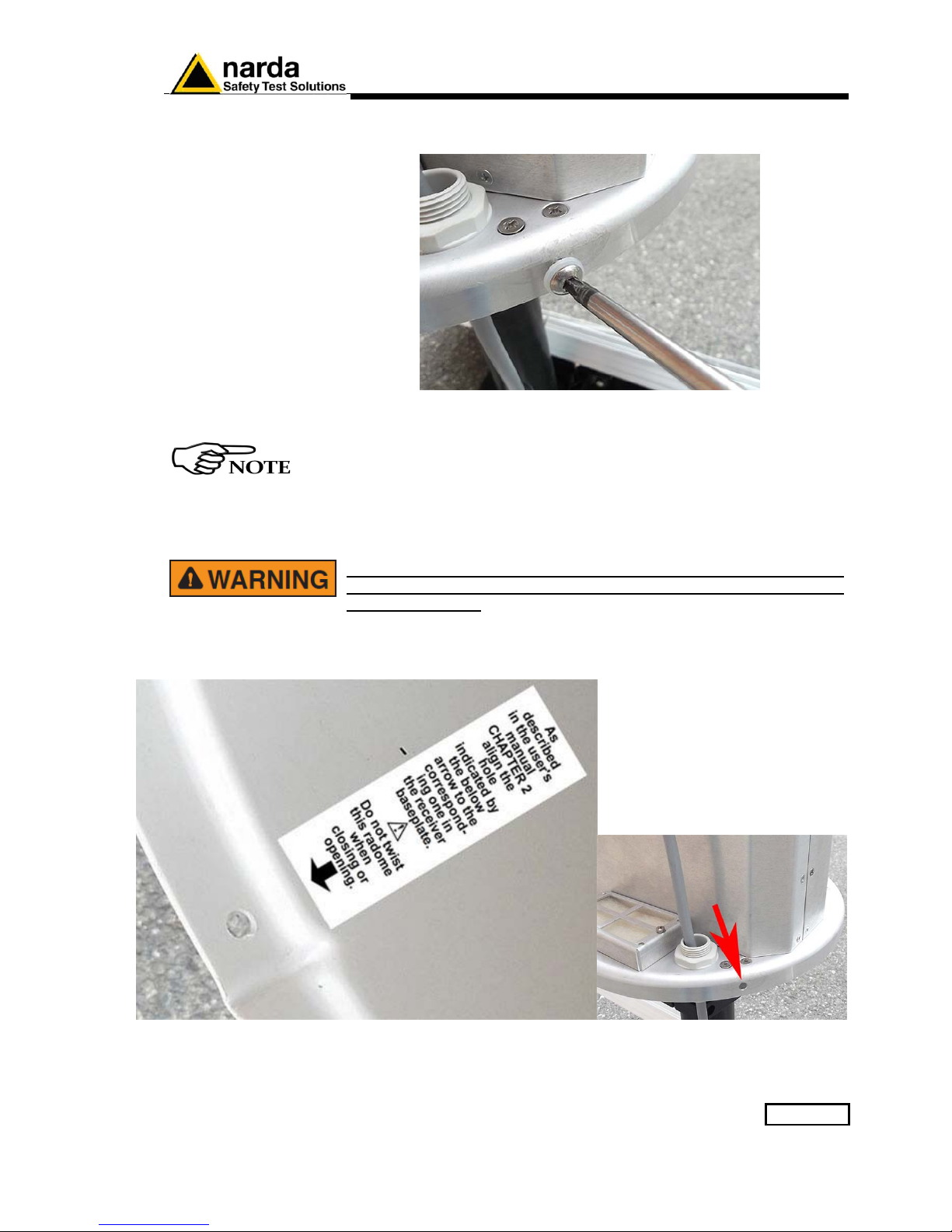
Remove the screws from the receiver baseplate to allow the Radome
mounting.
Considering that it has been designed for outdoor use and the main
operations are generally performed remotely by means of an internal
GSM modem, the AMS-8061 does not have any control or connection
on the outside of the protective case.
Controls and connections are available inside the protective case as
listed onward in this manual and can be reached by removing the
station Radome or the power pack cover.
The anti-tampering switch protrudes from the main unit.
Insert or remove along its axis the protective case; to avoid damage
the interlock do not turn the radome of the monitoring station when
closing or opening.
Place the Radome to align the hole near the inner label to the corresponding
one in the receiver baseplate
Page 40
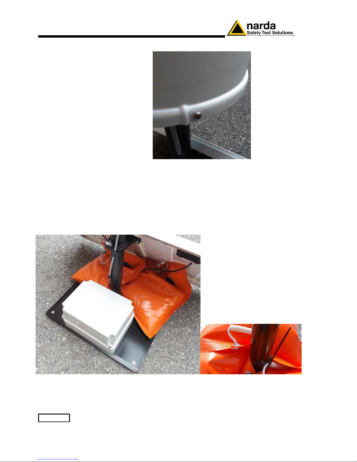
2-22 Installation and use
Tighten the four screws to fix the Radome.
2.6.1.13 Interlock
A microswitch inside the unit is tripped when the Radome is removed. It is
therefore possible to activate an alarm, to be sent to any mobile phone
warning of any attempts to tamper with the device.
2.6.1.14 Bags
The AMS-8061 is usually installed outdoors where atmospheric agents,
especially strong winds, can endanger its stability.
To ensure the necessary stability under the worst possible conditions, the
unit is supplied with three ballast bags that can be filled with water or sand
and fastened to the base of the mast.
Fasten the ballast bags to the mast using the plastic straps.
Page 41
Installation and use 2-23
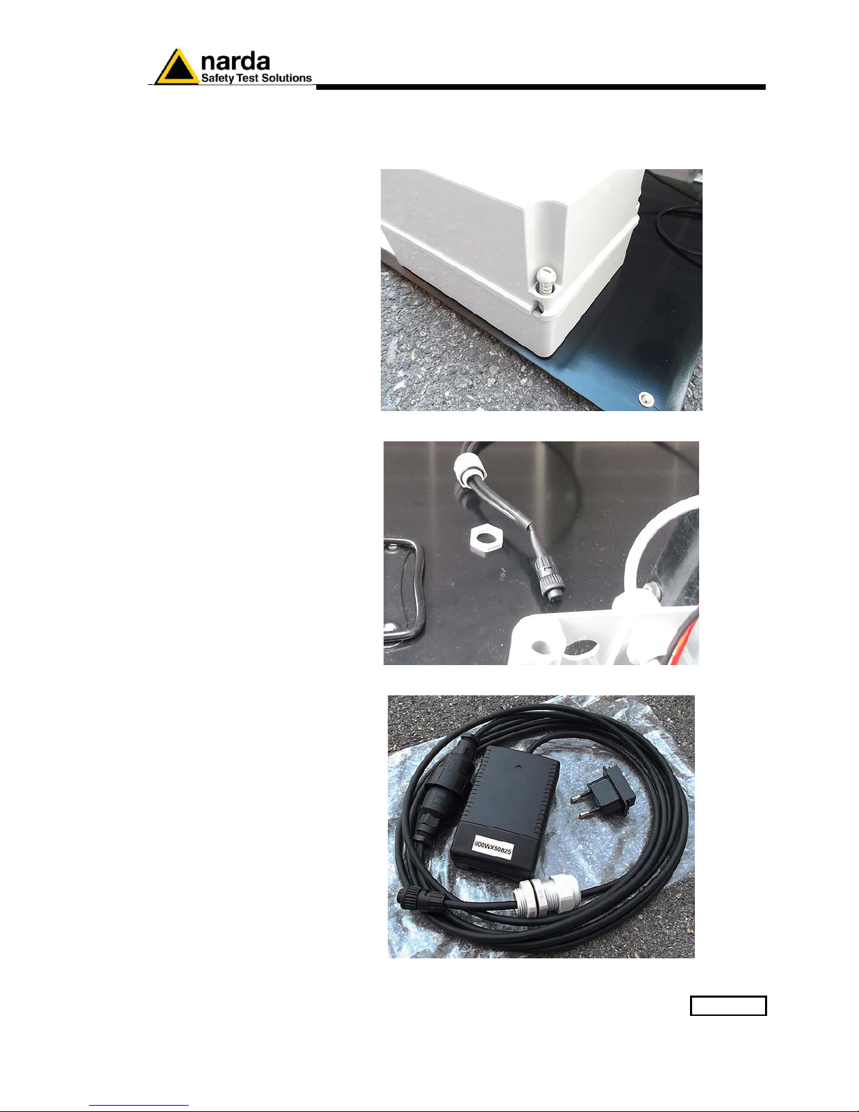
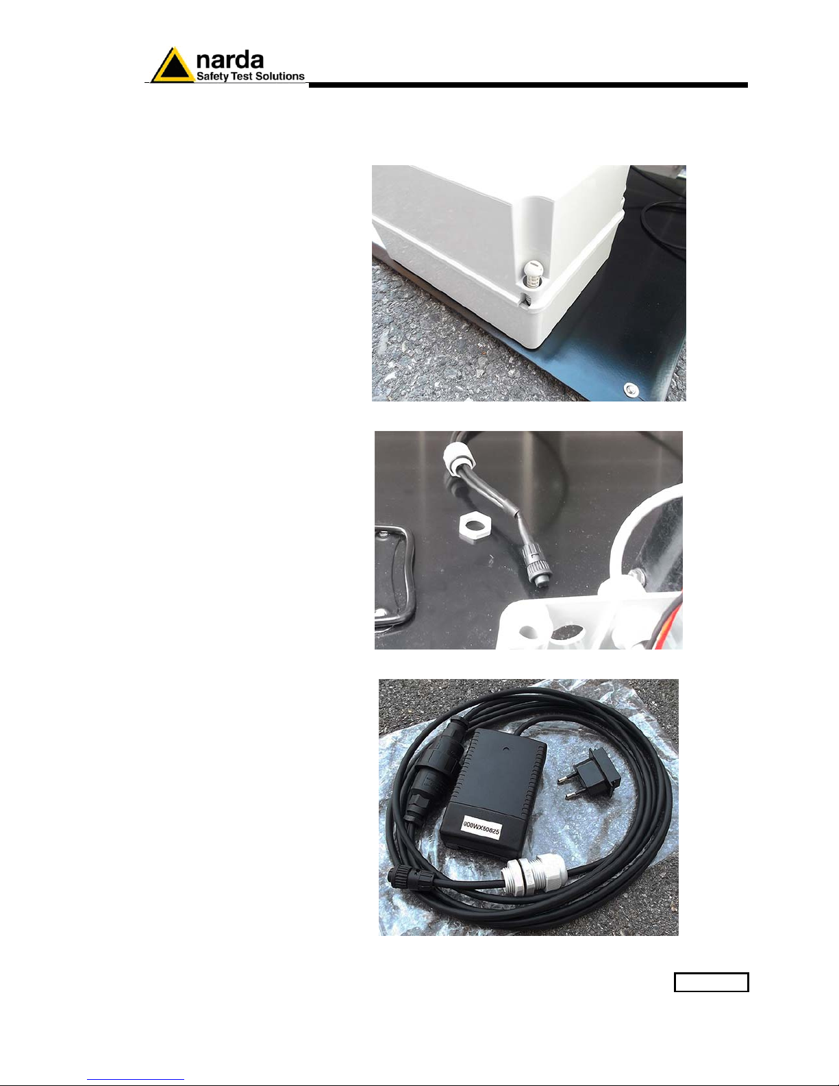
2.6.2 Battery charging
A complete battery charging should be completed (48 hours) before
starting measurements.
Remove the Power Pack cover.
Disconnect the solar panel from the Power Pack removing the chock.
Connect the provided power supply/battery charger for a complete charge.
Page 42
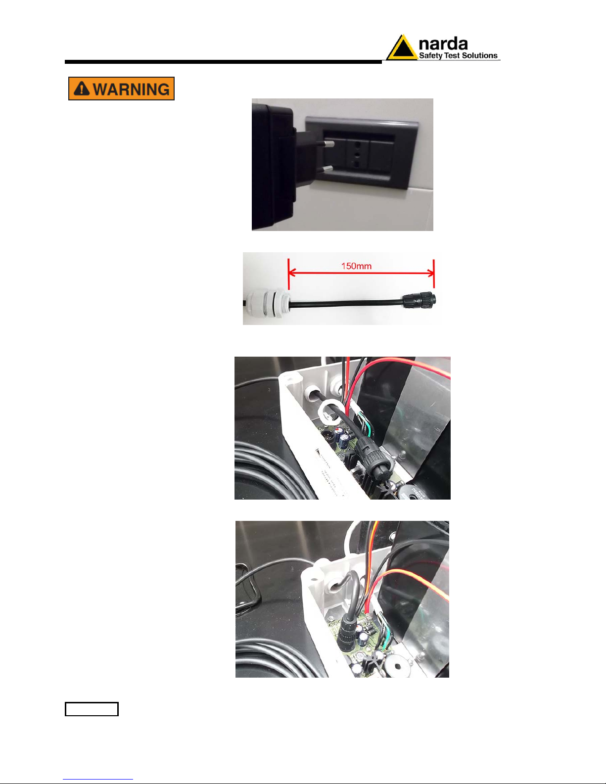
2-24 Installation and use
Plug the battery charger with the proper adapter to the mains outlet
before connect the multipole connector to the Power pack.
Fasten the cable to the strain relief.
Thread the cable through the hole in the box and screw the nut to fasten
the chock to the Power Pack.
Plug the multipole battery charger connector to the Power pack
Page 43
Installation and use 2-25
2.6.3 External power
supply
Execute the following wiring in the case an external power supply is
requested during measurements.
Remove the Power Pack cover.
Disconnect the solar panel from the Power Pack removing the chock.
Connect the provided power supply/battery charger.
Page 44
2-26 Installation and use
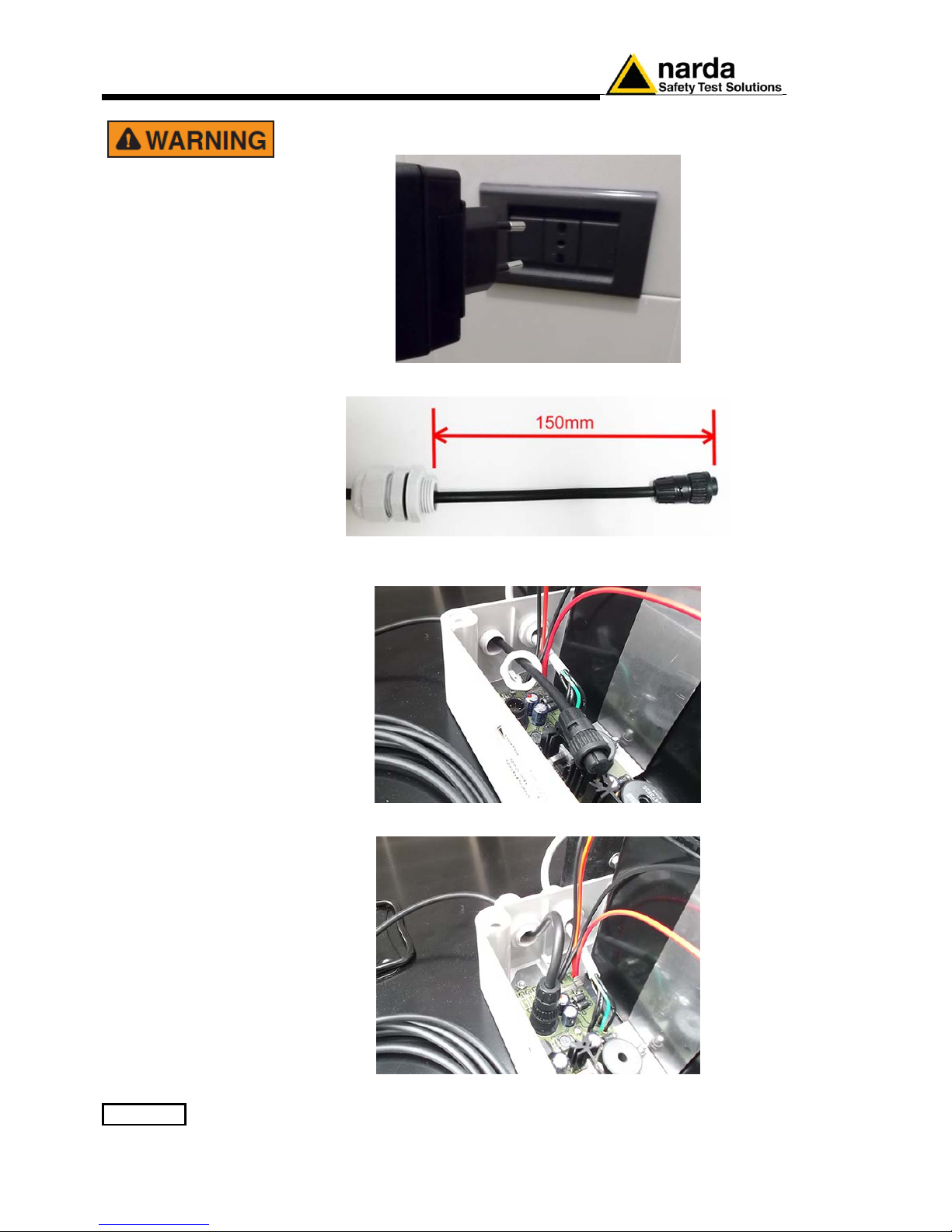
Plug the battery charger with the proper adapter to the mains outlet
before connect the multipole connector to the Power pack.
Fasten the cable to the strain relief.
Thread the cable through the hole in the box and screw the nut to fasten
the chock to the Power Pack.
Plug the multipole battery charger connector to the Power pack
Page 45

Installation and use 2-27
2.7 How to switch the
GSM modem on
On the AMS-8061 the GSM modem can be switched on in three different
ways:
1. Programmed (the User decides when the modem has to be switched
on and for how long).
2. Spontaneous (the AMS-8061 switches the GSM modem on whenever
there is an alarm )
3. Automatic (the AMS-8061 switches the GSM modem on automatically
when certain conditions arise)
2.8 Programmed
Mode
The Programmed mode consists of setting a time for switching the modem
on and off and the repetition interval.
The parameter “Hours and Minutes” specifies at what time of the day the
GSM modem will be switched on and put in Stand-By mode.
The “Stand-By” parameter defines for how many hours the GSM modem
remains on.
The parameter “Every” defines the repetition interval or after how many
hours, from the last programmed activation, the GSM modem will switch on
again.
The parameter “Every” must be a submultiple of 24 ( 1, 2, 3, 4, 6, 8, 12, 24)
in order to have every day the same timing.
2.9 Spontaneous
mode
In Spontaneous mode, whenever an alarm condition occurs or when the
normal conditions are restored (e.g. exceeding the threshold value set for
the field intensity or returning below the threshold) the GSM is switched on
directly by the AMS-8061 either to make a call or to send an SMS
(depending on the settings) to the modem number(s) memorized.
Afterwards, the GSM remains on stand-by for 15 minutes.
2.10 Automatic mode
The following condition turns the GSM modem on independently from the
setting:
- If both Stand-By parameters (“Schedule for Modem” and “Schedule for
SMS”) are settled to zero the GSM will switch on in stand by mode at 11.00
AM every day and will stay on for 3 hours, otherwise it could not be called
at all.
Page 46
2-28 Installation and use
2.11 Selective unit
Switching ON/OFF
The selective unit is OFF every time the battery voltage is lower than 11 V.
2.12 RF signals of
dangerous intensity
The antenna used in the AMS-8061 and the receiver input stage contain
highly sensitive elements.
Never place the unit in an electrical field higher than the maximum allowed
level.
The type of the mounted antenna is automatically sensed.
No operation is required after the antenna installation or replacement.
2.13 Controlling the
internal battery
The internal battery is automatically recharged by the solar panel (if
connected) or by an external power source. The charge can be checked by
remote using the proper command; a battery alarm can also be set, if
necessary.
The lead batteries with a nominal voltage of 12V can be damaged if
left for a long period with voltage below 11,58 V.
Below this value chemical processes, that could damage them, begin.
The AMS-8061 batteries apply a technology to reduce this
phenomenon.
Furthermore the supply circuit disconnect the load (switching the
unit off) when the battery voltage is low.
Anyway, if not used, the station should be switched off.
Battery should be recharged if the station has not to be used for a
long period.
Any part of the instrument, including the battery, can only be
replaced by NARDA, therefore in case of any damages to parts and/or
malfunctions, please contact the NARDA Service Center.
Page 47
Installation and use 2-29
2.14 Suggestions and
checking list to
define Area monitor
problems.
The following are some recommended check points to be done to insure
the proper usage of the Area Monitor:
1. Is the 8061 switched ON?
2. Is the GSM modem Led ON?
3. Is the battery charged correctly?
To charge the battery it is not necessary to switch the station on.
Battery charging takes about 40 hours.
To avoid any battery problem, you can connect the battery charger to
the area monitor and call it via Cable. In this way the area monitor
should always respond.
4. Is the GSM modem programmed to be ON during the period you want
to call the Area monitor? If not, turn the Area monitor off and ON again.
5. Can you hear the typical noise coming out from the speaker of the
modem connected to the PC during the calling process? If not, your
modem is probably off or the software is using a different COM port to
which the modem is not connected.
6. What kind of telephone line (dedicated or GSM) are you using to call
station from its PC? Try to use the fax machine telephone line.
7. Are you sure that the modem and the telephone line are able to
support data calls?
8. Is the modem or the RS232 Cable connected to the correct COM port
of the PC?
9. Is the modem correctly installed on PC (hardware and software)?
Use diagnostic procedure to verify the correct installation and be
sure the modem has all the protocols required for this kind of data
communications – low cost modem for internet application only, may
not support Area Monitor application.
10. Is the SIM Card in the Area Monitor available for Tx and Rx data
communication from mobile to mobile? Has the PIN code been
removed?
If the communication with the area monitor is successful only by
RS232 cable, the problem may lay on the modem or its antenna
If the modem of your PC is used as Windows “Fax Printer” peripheral
it may be not available for the station. In this case, disabling the
setting for the use of the modem in the “Fax Printer” will restore the
normal operation.
To get a fast response from NARDA support center it is very
important to provide always a picture reporting the system setup
(storing settings, alarms status, start and stop of the download, etc..)
to give a correct description of the conditions under which the area
monitor was working during the faulty of the unit. Better if you can
also provide the telephone number of the area monitor (A SIM card
allowed for international data calls should be available for remote
diagnostic).
Remote diagnostic will offer a better understanding of all problems
concerning the status of the Area monitor and to eliminate your local
communication problems.
Page 48

2-30 Installation and use
This page has been left blank intentionally
Page 49

GPRS and FTP 3-1
3 – GPRS and FTP
3.1 Introduction
As opposed to point-to-point Modem connection, which needs that both
uploader and downloader are connected at the same time, GPRS via FTP
mode works instead on a server way. Indeed, the monitoring station
regularly stores all data on a server while a client application can retrieve
them later on. This means there is no necessity to be on-line at the same
time.
Moreover, more clients can share the same data as all data are stored in a
server and stay there until they are deleted (by a client).
The method used is FTP.
Similarly to MODEM GSM schedule, which dials a remote Modem
number stored in AMS-8061 telephone directory, GPRS establishes a
connection using Provider Name, Username etc. stored in its
memory.
Basically, at schedules, the AMS-8061 regularly establishes, via GPRS, a
connection to the server and through FTP:
• First it loads, if any, all the (new) settings which have been written
by the (client) application.
• Then it writes all data that have been requested by the
application.
• Finally it erases all previous required settings in order to avoid
reloading them at the next connection. Note that data related to
field measurements are never deleted by the station.
After that the connection is terminated.
Although the AMS-8061 can operate in both modes, MODEM and GPRS, it
cannot do it at the same time. This means that a setting command is used
to configure the AMS-8061 to work either via MODEM way or via GPRS.
Document AMS8061EN-81008 -1.22 - © NARDA 2018
Page 50

3-2 GPRS and FTP
3.2 Structure
All data exchange is done on the directory named as the serial number of
the monitoring station itself. That is in order to avoid having multiple stations
that store on same directory and, at the same time, having a unique location.
Here, an example of directory structure:
FTP_Root
000WE80201
8061.CFG
8061.set
8061FLD.TXT
17_08_01_07_09_.D61
000WE80202
8061.CFG
8061.set
8061FLD.TXT
\ 20_00_01_07_09_.D61
The User must ensure that the directory is already present on the FTP
root as the AMS-8061 will not create it.
Page 51
GPRS and FTP 3-3
3.3 Configuration (read)
Whenever the AMS-8061 connects to GPRS and accesses to FTP, it looks
for a file named 8061.CFG in its directory (its serial number). If the file is
present, the AMS-8061 retrieves it and calculates the checksum in order to
use it and thus get the new configuration. If the checksum is wrong, the file
is discarded otherwise the new configuration is taken.
Is important to note that the new setting will not take effect immediately but
only after the connection is closed.
All figures are Little Endian notation unless differently specified.
The structure of the configuration file is as follows.
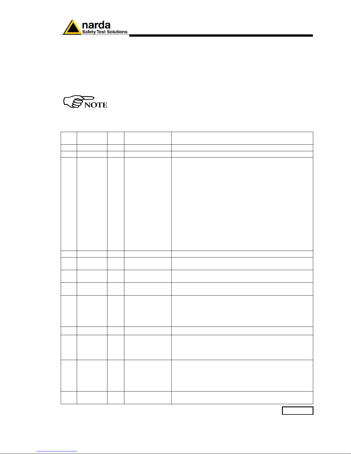
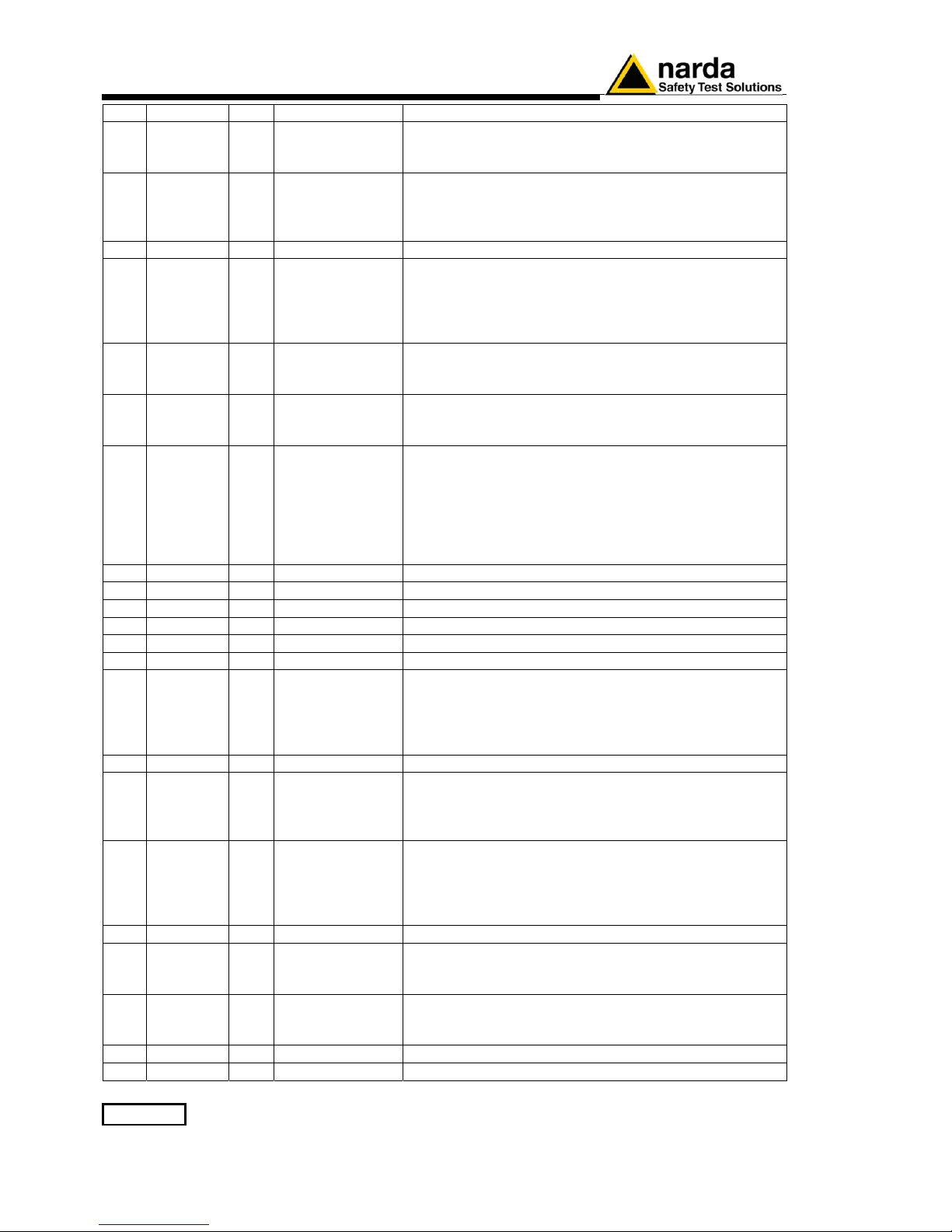
Pos Name Size
Byte
Type Description
0 ChkSum 2 Unsigned int Check sum (see the related paragraph)
2 idstation 34 Char The name of Station. This is a null terminated string.
36 Mask
alarm
2 Unsigned int
Being Bits this is
BIG endian
The mask of Alarm is a bit mask where ‘1’ means Alarm
Enabled while ‘0’ is Alarm Disabled. Here is a list
alarms.
0x0001-> MAX threshold Field OUT.
0x0002-> Warning threshold Field OUT.
0x0010-> LOCK OUT.
0x0080-> Low Battery Voltage OUT
0x0004-> Antenna OUT
0x0020-> Temperature
0x0040-> Relative Humidity
0x0008-> MAX threshold Field IN.
0x0100-> Warning threshold Field IN.
0x0400-> LOCK IN.
0x0800-> Low Battery Voltage IN
0x0200-> Antenna IN
38 Reserved 1 Unsigned char None
39 AvgRms 1 Unsigned char The way of averaging. If ‘AvgRms’ is 0 then is arithmetic
average otherwise is Root Mean Square
40 MaxThr 4 Float A little endian floating point figure that represents Max
threshold used for Alarm.
44 WarnThr 4 Float A little endian floating point figure that represents
Warning threshold used for Alarm.
48 Logger 1 Unsigned char This parameter sets the rate of the logger as follows
“1” ->1 minute
“2” ->2 minutes
“3” ->6 minutes
“4” ->15 minutes
49 reserved 1 Unsigned char None
50 Naver 2 Unsigned int This parameter represents the averaging time for
Warning and Alarm threshold. It is expressed as 4 times
the averaging time. For example a 6 min time is reported
as 24
52 GPRS
Appoint
2 Unsigned int This parameter represents the scheduled time for
connecting to GPRS of the day. It is expressed in
minutes elapsed since midnight.
For example the schedule 12:30 would be (12*60)+30
=750
54 GPRS
Ton
1 Unsigned char This parameter represents the time the GSM remains
ON after a GPRS connections. It is expressed in quarter
Page 52
3-4 GPRS and FTP
of hour.
55 GPRS
Interval
1 Unsigned char This parameter represents the interval between GPRS
connections (starting from the first connection which is
done at Appoint). It is expressed in hours.
56 Prxon 1 Unsigned char This is the flag for connecting to GPRS upon alarms.
If bit 0x01 is ‘1’ and one or more unmasked alarm is set,
a GPRS connection is done as it was for schedule.
Note that bit 0x08, the GPRS Flag, must always be ON.
57 Reserved 1 Unsigned char None
58 SMS
Sched
2 Unsigned int This parameter represents the scheduled time for SMS
schedule of the day. It is expressed in minutes elapsed
since midnight.
For example the schedule 12:30 would be (12*60)+30
=750
60 SMS
Ton
1 Unsigned char This parameter represents how long the GSM remains in
stand-by mode after a SMS connection. It is expressed
in quarters of hour.
61 SMS
Interval
1 Unsigned char This parameter represents the interval between SMS
connections (starting from the first connection which is
done at Appoint). It is expressed in hours.
62 SMS
Xon
1 Unsigned char This is a double flag for sending a report and alarm on
SMS.
If bit 0x01 is ‘1’ and one or more unmasked alarm is set,
a “ALR” like SMS is sent to the number stored in the
SMS telephone directory.
If bit 0x02 is ‘1’ a “RPT” like SMS is sent to the number
stored in the SMS telephone directory.
63 Reserved 1 Unsigned char Reserved
64 Reserved 2 Unsigned int Reserved
66 Reserved 1 Unsigned char Reserved
67 Reserved 1 Unsigned char Reserved
68 Reserved 1 Unsigned char Reserved
69 Reserved 1 Unsigned char Reserved
70 Ethernet
Sched
2 Unsigned int This parameter represents the scheduled time for
Ethernet schedule of the day. It is expressed in minutes
elapsed since midnight.
For example the schedule 11:08 would be (11*60)+8
=668
72 Reserved 1 Unsigned char Reserved
73 Ethernet
Interval
1 Unsigned char This parameter represents the interval between Ethernet
connections (starting from the first connection which is
done at Ethernet Sched). It is expressed in hours and it
can be either 12 or 24.
74 Ethernet
Schedule
Active
1 Unsigned char This parameter enables/disables Ethernet Scheduling
When “Ethernet Schedule Active” = 0x02 the Ethernet
activity is regulated by “Ethernet Sched”.
Instead, when “Ethernet Schedule Active” is 0 the
Ethernet is OFF
75 Reserved 3 Unsigned char Reserved
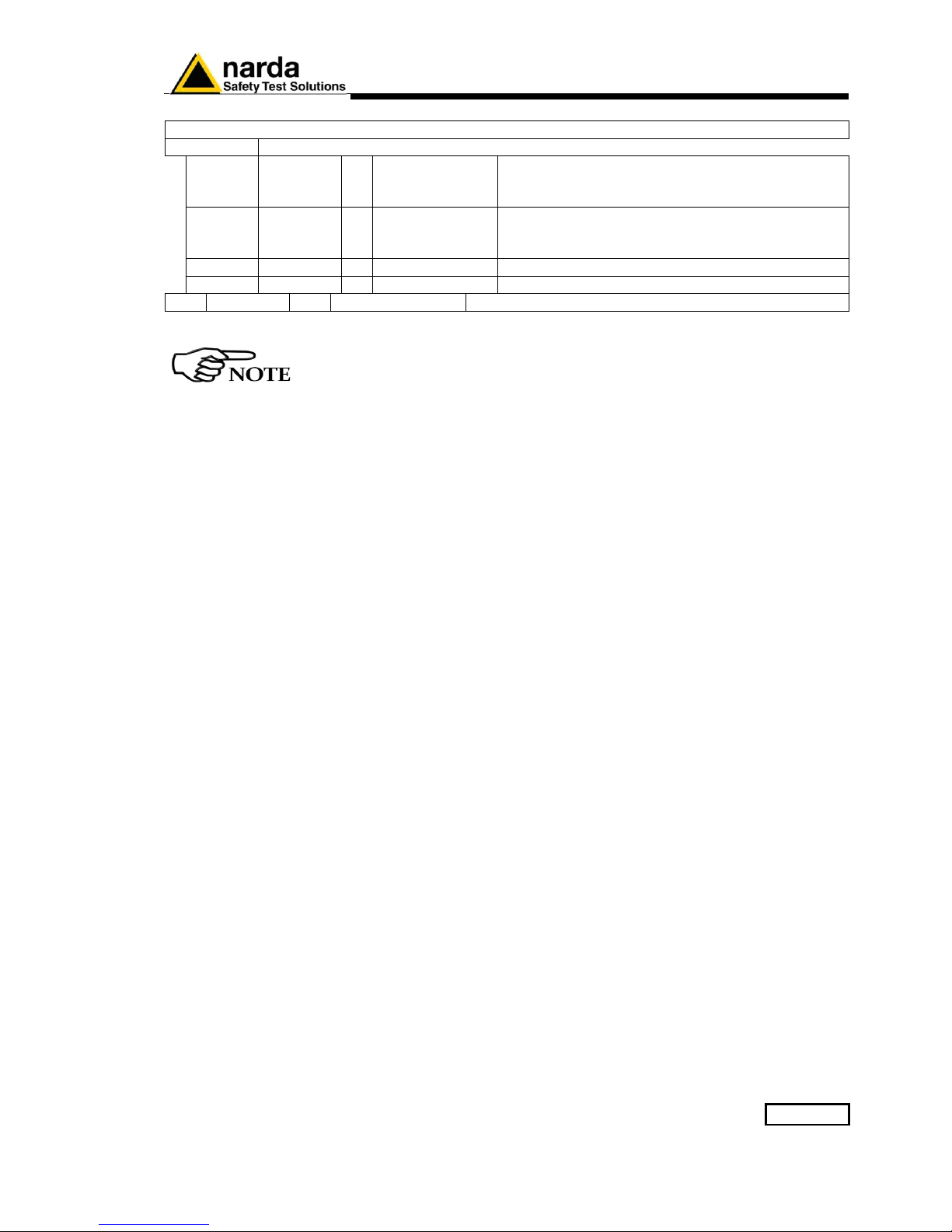
78 StartFreq 4 float Little Endian 32bit IEEE floating point number
representing the start frequency of the first band and it is
expressed in Hz.
82 StopFreq 4 float Little Endian 32bit IEEE floating point number
representing the Stop frequency of the first band and it is
expressed in Hz.
86 Reserved 1 Unsigned char Reserved, it must be 0
87 Reserved 1 Unsigned char
Page 53
GPRS and FTP 3-5
19 bands follow here exactly as the above described band 1.
n= 1 to 19
n*10+78 StartFreq 4 float Little Endian 32bit IEEE floating point number
representing the start frequency of the n band and
it is expressed in Hz.
n*10+82 StopFreq 4 float Little Endian 32bit IEEE floating point number
representing the Stop frequency of the n band and
it is expressed in Hz.
n*10+86 Reserved 1 Unsigned char Reserved, it must be 0
n*10+87 Reserved 1 Unsigned char Reserved
278 Reserved 8 Unsigned char Reserved
The checksum must be calculated starting from idStation (position 2) up to
(included) position 285 for a total of 284 bytes.
Page 54

3-6 GPRS and FTP
3.4 FLD File (Read) After having dealt with the configuration file 8061.CFG, the AMS-8061
check for the presence of a file named 8061FLD.TXT.
This is an ASCII file which contains the date of the first requested record
and the number of them.
The syntax is: FLD HH:mm;GG/MM/YY;n where:
• HH is hour of the day.
• mm is minute of the day.
• GG is the day.
• MM is the month.
• YY is the year
• n is the number of records required (if n=”---“ then all records
starting from the date/hour up the last recorded record will be
uploaded).
For example the string FLD 18:13;23/04/14;100
Asks for 100 records from the 23
th
of April 2014 at 18:13.
If, instead, the string would have been FLD 18:13;23/04/14;---
It would ask for all records from the 23
th
of April 2014 at 18:13 up to now.
in case of “---“ (up to now option), in order to avoid huge files and
long transfer time, the number of records will be limited to 5000.
Once the AMS-8061 has read the file 8061FLD.TXT, it deletes it. It will be
replaced later with the newer self created 8061FLD.TXT which reflects the
last record.
This solves the continuity of records even without any external intervention.
Indeed, for every connection the AMS-8061 uploads the records and writes
a new FLD file which reports the date/hour of last record so that next
connection will continue from this having thus an uninterrupted series of
records.
Page 55

GPRS and FTP 3-7
3.5 Record File (Write)
After having read the FLD file, which informs the AMS-8061 about which
records have to be uploaded, it writes a file named
HH_mm_GG_MM_YY.D61 where:
• HH is hour of the day.
• mm is minute of the day.
• GG is the day.
• MM is the month.
• YY is the year
The content of this file is binary and reflects what is described, according to
the setting, in the specific paragraph:
• D61 Structure
Please refer to it for the correct interpretation of data.
3.6 FLD File (Write) After having written the record file HH_mm_GG_MM_YY.D61, the AMS-
8061 writes the file named 8061FLD.TXT which replaces the old one.
This is an ASCII file which contains the date of the last uploaded record
and terminates with the string “---“.
The content will be therefore: FLD HH:mm;GG/MM/YY;--- where:
• HH is hour of the day.
• mm is minute of the day.
• GG is the day.
• MM is the month.
• YY is the year
For example the string FLD 20:30;23/04/14;---
Says that the last updated record is related to the date of 23
th
of April 2014
at 20:30.
If a client does not necessitate a specific period, and needs a simple
continuous data logger, there is no need to write any FLD File as the
system is self-sufficient.
3.7 Event File (Write)
After having written the FLD file, the AMS-8061 writes a file named
HH_mm_GG_MM_YY.TXT where:
• HH is hour of the day.
• mm is minute of the day.
• GG is the day.
• MM is the month.
• YY is the year
Which represents the events file.
This is an ASCII file which contains all the new events since last
connection.
Alternatively, soliciting a connection, by the SMS command, different
event history can be retrieved as follows:
• SCGNA : all the stored events are written in EVENT.TXT file
• SCGNL : The last 20 events are written in EVENT.TXT file
The content of EVENT file is the chronological history of all events up to
the time of connection (RTC setting assumed to be correct).
Page 56
3-8 GPRS and FTP
3.8 Setting Status. (Write)
After having written the EVENT.TXT file, the AMS-8061 writes a file named
8061.set which reflects the configuration of the monitoring station.
Similarly to the Configuration 8061.CFG the file is binary.
This file is solely intended for reading as it is ignored by AMS8061 and
therefore any change of it will be discarded. Use 8061.CGF if you want to
change any setting.
All figures are in Little Endian notation.
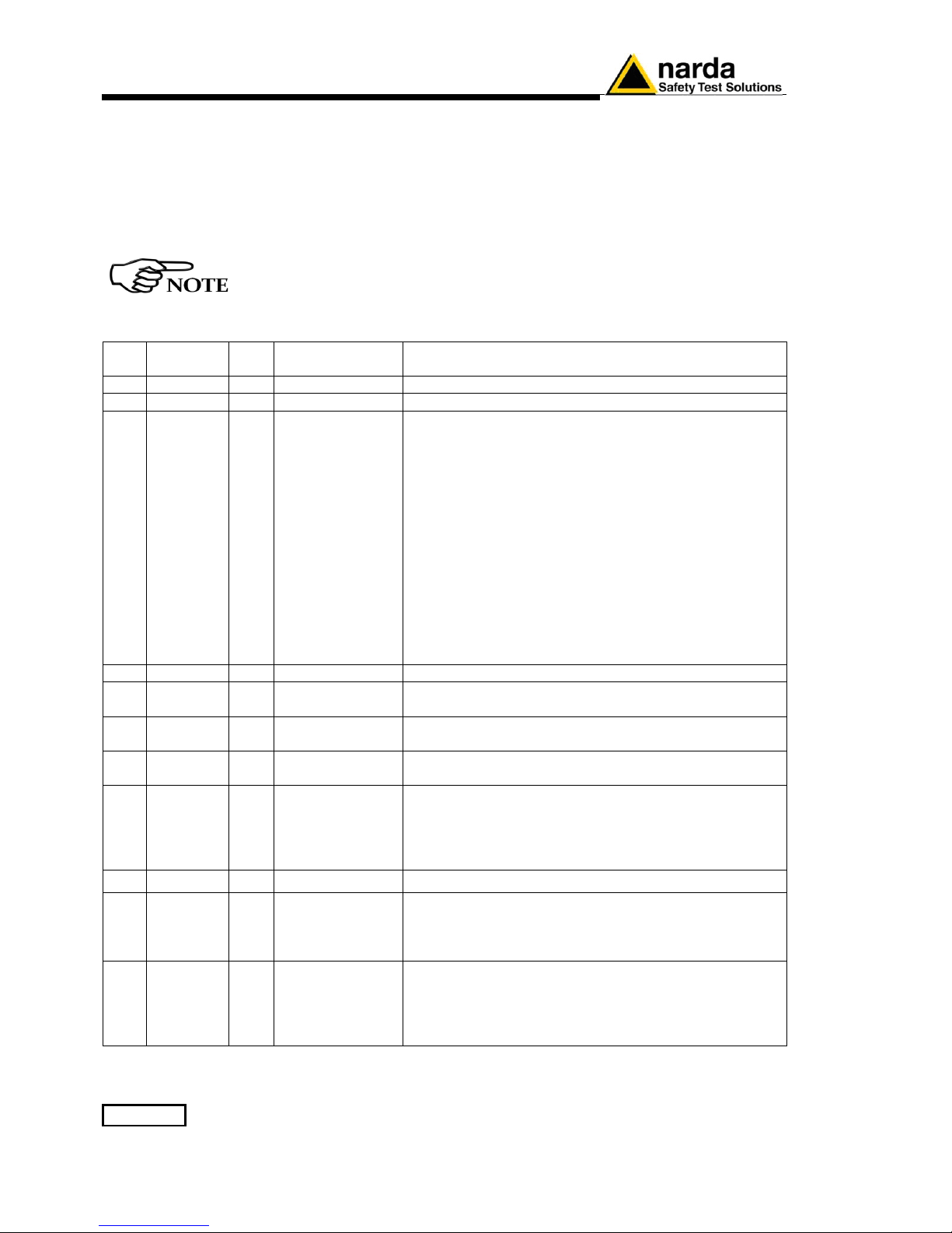
The structure of the configuration file is as follows.
Pos Name Size
Byte
Type Description
0 ChkSum 2 Unsigned int Check sum (see the related paragraph)
2 idstation 34 Char The name of Station. This is a null terminated string.
36 Mask
alarm
2 Unsigned int
Being Bits this is
BIG endian
The mask of Alarm is a bit mask where ‘1’ means Alarm
Enabled while ‘0’ is Alarm Disabled. Here is a list
alarms.
0x0001-> MAX threshold Field OUT.
0x0002-> Warning threshold Field OUT.
0x0010-> LOCK OUT.
0x0080-> Low Battery Voltage OUT
0x0004-> Antenna OUT
0x0020-> Temperature
0x0040-> Relative Humidity
0x0008-> MAX threshold Field IN.
0x0100-> Warning threshold Field IN.
0x0400-> LOCK IN.
0x0800-> Low Battery Voltage IN
0x0200-> Antenna IN
38 Reserved 1 Unsigned char None
39 AvgRms 1 Unsigned char The way of averaging. If ‘AvgRms’ is 0 then is arithmetic
average otherwise is Root Mean Square
40 MaxThr 4 Float A little endian floating point figure that represents Max
threshold used for Alarm.
44 WarnThr 4 Float A little endian floating point figure that represents
Warning threshold used for Alarm.
48 Logger 1 Unsigned char This parameter sets the rate of the logger as follows
“1” ->1 minute
“2” ->2 minutes
“3” ->6 minutes
“4” ->15 minutes
49 reserved 1 Unsigned char None
50 Naver 2 Unsigned int This parameter represents the averaging time for
Warning and Alarm threshold. It is expressed as 4 times
the averaging time. For example a 6 min time is reported
as 24
52 GPRS
Appoint
2 Unsigned int This parameter represents the scheduled time for
connecting to GPRS of the day. It is expressed in
minutes elapsed since midnight.
For example the schedule 12:30 would be (12*60)+30
=750
Page 57
GPRS and FTP 3-9
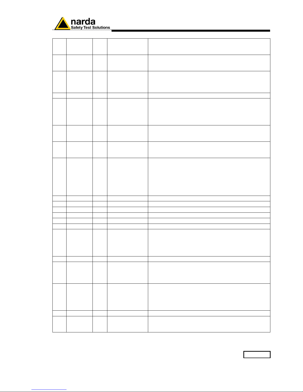
54 GPRS
Ton
1 Unsigned char This parameter represents the time the GSM remains
ON after a GPRS connections. It is expressed in quarter
of hour.
55 GPRS
Interval
1 Unsigned char This parameter represents the interval between GPRS
connections (starting from the first connection which is
done at Appoint). It is expressed in hours.
56 Prxon 1 Unsigned char This is the flag for connecting to GPRS upon alarms.
If bit 0x01 is ‘1’ and one or more unmasked alarm is set,
a GPRS connection is done as it was for schedule.
Note that bit 0x08, the GPRS Flag, must always be ON.
57 Reserved 1 Unsigned char None
58 SMS
Sched
2 Unsigned int This parameter represents the scheduled time for SMS
schedule of the day. It is expressed in minutes elapsed
since midnight.
For example the schedule 12:30 would be (12*60)+30
=750
60 SMS
Ton
1 Unsigned char This parameter represents the time the GSM remains
ON after a SMS connections. It is expressed in quarters
of hour.
61 SMS
Interval
1 Unsigned char This parameter represents the interval between SMS
connections (starting from the first connection which is
done at Appoint). It is expressed in hours.
62 SMS
Xon
1 Unsigned char This is a double flag for sending a report and alarm on
SMS.
If bit 0x01 is ‘1’ and one or more unmasked alarm is set,
a “ALR” like SMS is sent to the number stored in the
SMS telephone directory.
If bit 0x02 is ‘1’ a “RPT” like SMS is sent to the number
stored in the SMS telephone directory.
63 Reserved 1 Unsigned char Reserved
64 Reserved 2 Unsigned int Reserved
66 Reserved 1 Unsigned char Reserved
67 Reserved 1 Unsigned char Reserved
68 Reserved 1 Unsigned char Reserved
69 Reserved 1 Unsigned char Reserved
70 Ethernet
Sched
2 Unsigned int This parameter represents the scheduled time for
Ethernet schedule of the day. It is expressed in minutes
elapsed since midnight.
For example the schedule 11:08 would be (11*60)+8
=668
72 Reserved 1 Unsigned char Reserved
73 Ethernet
Interval
1 Unsigned char This parameter represents the interval between Ethernet
connections (starting from the first connection which is
done at Ethernet Sched). It is expressed in hours and it
can be either 12 or 24.
74 Ethernet
Schedule
Active
1 Unsigned char This parameter enables/disables Ethernet Scheduling
When “Ethernet Schedule Active” = 0x02 the Ethernet
activity is regulated by “Ethernet Sched”.
Instead, when “Ethernet Schedule Active” is 0 the
Ethernet is OFF
75 Reserved 3 Unsigned char Reserved
78 StartFreq 4 float Little Endian 32bit IEEE floating point number
representing the start frequency of the first band and it is
expressed in Hz.
Page 58
3-10 GPRS and FTP
82 StopFreq 4 float Little Endian 32bit IEEE floating point number
representing the Stop frequency of the first band and it is
expressed in Hz.
86 Reserved 1 Unsigned char Reserved, it must be 0
87 Reserved 1 Unsigned char Reserved
19 bands follow here exactly as the above described band 1.
n= 1 to 19
n*10+78 StartFreq 4 float Little Endian 32bit IEEE floating point number
representing the start frequency of the n band and
it is expressed in Hz.
n*10+82 StopFreq 4 float Little Endian 32bit IEEE floating point number
representing the Stop frequency of the n band and
it is expressed in Hz.
n*10+86 Reserved 1 Unsigned char Reserved, it must be 0
n*10+87 Reserved 1 Unsigned char Reserved
Page 59
GPRS and FTP 3-11
278 Reserved 8 Unsigned char Reserved
286 Status
alarm
2 Unsigned int
Being Bits this is
BIG endian
The status of Alarm contains the alarm bit by bit where ‘1’
means Alarm ON while ‘0’ is Alarm OFF. Here is a list
alarms.
0x0001-> MAX threshold Field OUT.
0x0002-> Warning threshold Field OUT.
0x0010-> LOCK OUT.
0x0080-> Low Battery Voltage OUT
0x0004-> Antenna OUT
0x0020-> Temperature
0x0040-> RH
0x0008-> MAX threshold Field IN.
0x0100-> Warning threshold Field IN.
0x0400-> LOCK IN.
0x0800-> Low Battery Voltage IN
0x0200-> Antenna IN
288 Temp 2 int This parameter shows the AMS-8061 Temperature.
It is ten times the last measured temperature.
Thus, in order to get actual temperature Temp should be
divided by 10
290 RH 2 Int This parameter shows the AMS-8061 Relative Humidity.
It is ten times the last measured Relative Humidity.
Thus, in order to get actual Relative Humidity, RH should
be divided by 10
292 Battery 2 Int This parameter shows the AMS-8061 current voltage.
It is hundred times the last measured Battery Voltage.
Thus, in order to get actual Battery Voltage, Battery
should be divided by 100
294 Reserved 186 None
480 Firmware 32 Char The Fw name and version. This is a null terminated string
Page 60
3-12 GPRS and FTP
3.9 GPRS – FTP Settings
In order to establish a GPRS connection and a FTP transfer, a number of
data are required which are divided into 2 main fields as follows. Each
fields cannot be more than 31 characters.
These commands cannot be executed via FTP/GPRS (because they would
need to be already correctly set).
GPRS Connection Data
Field Description Setting command
Command to be issued by
either SMS or RS232
GPR0
APN
Access Point
Name
The provider name of the GPRS bearer.
#SMSGPR0 <apn>*
where <apn> is Access Point
Name
Example:
#SMSGPR0 web.omnitel.it*
GPR1
GUN
User Name for
Gprs access
The User Name required for logging-in.
Sometimes this field might not be required and thus
can be left empty.
#SMSGPR1 <gun>*
where <gun> is the User
Name of GPRS access.
Example:
#SMSGPR1 MyGPRS*
GPR2
GPSW
Password for
Gprs access
The Password required for logging-in.
Sometimes this field might not be required and thus
can be left empty.
#SMSGPR2 <gpsw>*
where <gpsw> is the
Password of GPRS access.
Example:
#SMSGPR2 1234*
FTP Connection Data
Field Description Setting command
Command to be issued by
either SMS or RS232
GPR3
FUN
User Name for
FTP access
The User Name required for accessing to the FTP
server. This word is usually issued from the FTP
administrator and is nothing to do with the bearer.
#SMSGPR3 <fun>*
where <fun> is the User Name
for FTP.
Example:
#SMSGPR3 MyFTP*
GPR4
FPSW
Password for
FTP access
The Password required for accessing to the FTP
server. This word is usually issued from the FTP
administrator and is nothing to do with the bearer.
#SMSGPR4 <fpsw>*
where < fpsw > is the
Password for FTP.
Example:
#SMSGPR4 abcd*
GPR5
FIP
FTP IP
Address
This parameter is the server address for FTP ( IP
Address of FTP). Normally this is the static IP
Address that routes the file transferring process to
the wanted server
#SMSGPR5 <fip>*
where < fip > is the IP Address
for FTP.
Example:
#SMSGPR5 194.183.2.17*
Page 61
GPRS and FTP 3-13
MISC
Field Description Setting command
Command to be
issued by either
SMS or RS232
CGN
Connect GPRS
Now
This command starts a GPRS connection immediately. All the
procedures are then the same as it would for a scheduled
connection.
#SMSCGN*
CGNL
Connect GPRS
Now (Last
Events)
This command starts a GPRS connection immediately as for
CGN but it forces to have a EVENT.TXT file containing the
last 20 events instead of the most recent, and not yet loaded,
ones.
#SMSCGNL*
CGNA
Connect GPRS
Now (All
Events)
This command starts a GPRS connection immediately as for
CGN but it forces to have a EVENT.TXT file containing all the
events available instead of the most, and not yet loaded, ones.
#SMSCGNA*
CGNFW
Connect GPRS
Now and
update
Firmware
This command starts a GPRS connection immediately as for
CGN. Additionally, if the 2 firmware files are found, it updates
the firmware and reboots.
#SMSCGNFW*
CGNFWI
Connect GPRS
Now and
Immediately
update
Firmware
This command starts a GPRS connection immediately as for
CGN. Additionally, if the 2 firmware files are found, it updates
the firmware and reboots without uploading any records.
The difference from CGNFW is that it does not upload the
data before updating the FW thus all unloaded records are
lost.
#SMSCGNFWI*
NETE
Enable GPRS
protocol
This command enables the AMS-8061 to connect via GPRS
instead of point-to-point GSM-MODEM connection.
The reply is the same as for command ?TSM
#SMSNETE*
NETD
Disable GPRS
protocol
This command disables the AMS-8061 GPRS and enables
point-to-point GSM-MODEM connection.
The reply is the same as for command ?TSM
#SMSNETD*
STS id
Set Timedate
SMS
This command sets the internal real clock time by using the
SMS provider’s information.
To use it id (the AMS-8061 telephone number) must be sent.
This command works assumes that the SMS provider gives
the correct Clock/Date and its feedback is within 30 seconds.
The reply is sent only if the real time clock has been updated
and is the same as for the command “?CLK”
#SMSSTS
nnnnnnnn* where
nnnnnnnn is the
telephone number
of AMS-8061
Page 62

3-14 GPRS and FTP
3.10 Checksum
algorithm
As previously mentioned, there is a little endian 16 bit unsigned int which
is called checksum. The checksum is intended for verifying the reliability of
the array read mainly from the AMS-8061’s side as a corrupt configuration
could potentially make the AMS-8061 ineffectual.
Therefore the application must ensure that the checksum in the 8061.CFG
file reflects the actual state of the configuration setting. Otherwise, if the
checksum does not match the exact value, the new configuration will be
ignored.
The Checksum is calculated as the sum of all the bytes involved starting
from a seed of 0xAAAA.
Then, from the result the modulo 0x10000 is taken (which also means
truncating the result to 4 bytes).
Page 63
GPRS and FTP 3-15
3.11 D61 Structure,
Download
description
This paragraph describes the structure of a multiband record.
These records are created by either GPRS/ftp enabled (files D61) or
“?FLS” command.
3.11.1 Command Mode
Sintax Description
?FLS HH:mm,dd/MM;n
Request for n samples starting from Hour HH and minute mm of the day dd
of the month MM of the current year. In case MM is higher than current month,
the referred year is the past one.
For example, the command #SM ?FLS 13:00,01/08;60* asks for 60 measures
starting from 13:00 of the 1
st
of August
This answer is a block of binary data
The block of bytes in replying to #SM ?FLS HH:mm,GG/MM;n command
is as follows:
A Header: made of #SM FLS=*<CR><LF> (11 bytes)
A series of ( 32 bytes + 16* Number of Bands) per sample as shown in the
following table.
A final Checksum as described at the end of this document.
3.11.2 GPRS/FTP Mode
At GPRS schedule a file named HH_mm_dd_MM_yy_.D61 is created (see
the proper paragraph in this chapter).
This file contains ( 32 + 16* Number of Bands) * n bytes (where n is the
number of requested records).
All figures in this document are LITTLE ENDIAN
Page 64
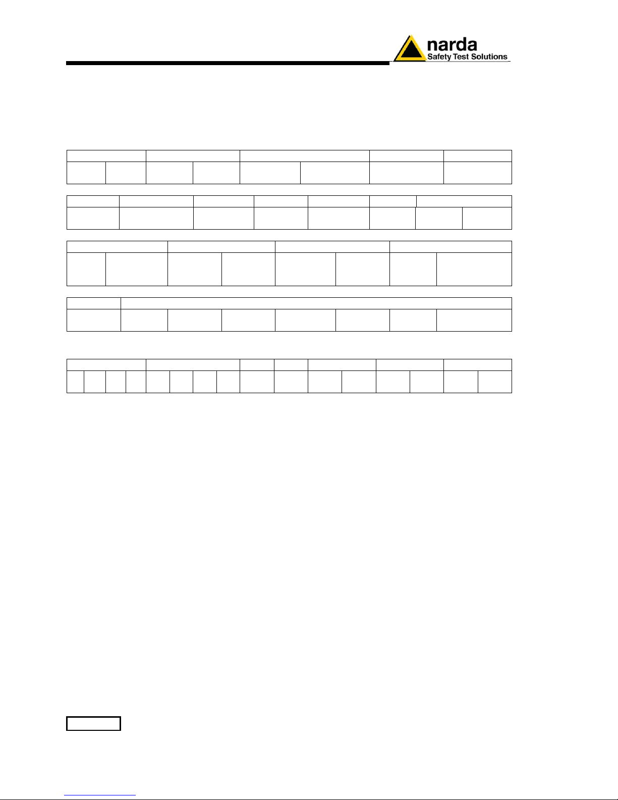
3-16 GPRS and FTP
3.11.3 Selective
Multiband
Structure
description
Header
Reserved Reserved Reserved Charge RH
Byte 1 Byte 2 Byte 3 Byte 4
Byte 5
Byte 6
Byte 7
Byte 8
Battery Temperature Alarm PERTS PROC Month DateTime
Byte 9
Byte 10
Byte 11
Byte 12
Byte 13 Byte 14 Byte 15 Byte 16
Latitude int Latitude Fract Longitude int Longitude Fract
degree
Byte
17
minute
Byte 18
Byte 19 Byte 20
degree
Byte 21
minute
Byte 22 Byte 23
Byte 24
NOB Reserved
Byte 25 Byte 26
SelRate
Byte 27
LstBnd
Byte 28 Byte 29 Byte 30 Byte 31 Byte 32
Sub-Band(s) 1- NOB
Freq_Start Freq_Stop RBW Res Peak Avg Reserved
+0 +1 +2 +3 +4 +5 +6 +7 +8 +9 +A +B +C +D +E +F
Page 65
GPRS and FTP 3-17
The figure named Charge is shown as follows:
Charge
D07 D06 D05 D04 D03 D02 D01 D00
Byte 7 8 bit unsigned integer
This value represents the charging current of the AMS-8061 battery. The number should be considered
as an unsigned 8 bit integer.
To get the value in CH_Units the following formula should be used:
CH_Units)= Charge * 0.78
If, for example, the 8 bit figure named Charge is 0x57 (decimal 87) then the CH_Units would be ~68
The figure named RH is shown as follows:
D07 D06 D05 D04 D03 D02 D01 D00
RH
Byte 8
8 bit unsigned integer
(RH)
This value is the relative Humidity and is expressed in percent . The number should be considered as
an unsigned 8 bit integer.
If, for example, 8 bit figure named RH is 0x32 (decimal 50) then the value of RH would be 50%
The figure named Battery is shown as follows:
D07 D06 D05 D04 D03 D02 D01 D00
Battery
Byte 9
8 bit unsigned integer
(Voltage)
It is the voltage of the AMS-8061 battery. The number should be considered as an unsigned 8 bit
integer. To get the correct value of the battery voltage the following formula is used: Volt = Voltage *
0.133
If, for example, 8 bit figure named Battery is 0x5D (decimal 93) then the battery voltage will be ~12.37
V
Page 66
3-18 GPRS and FTP
The figure named Temperature is shown as follows:
D07 D06 D05 D04 D03 D02 D01 D00
Temperature
Byte 10
SPR
FLAG
7 bit unsigned integer
(Temperature)
It is the Temperature recorded in the interval. The number should be considered as an unsigned 7 bit
integer. In order to avoid negative figure an offset of 40 degrees centigrade is added thus, to get the
correct value of the temperature, the following formula is used: T Centigrade = Temp - 40.
SPR Flag is a reserved one and should be masked (for example Temp & 0x7F).
If, for example, 8 bit figure named Temp is 0x3f (decimal 63) then the temperature will be 23°C
The figure named ALARM is shown as follows:
D07 D06 D05 D04 D03 D02 D01 D00
ALARM
Byte 11
ABAT ARH ATMP ALCK
Reserved
ASENS AWRN AALR
It is the block of alarms recorded in the interval. Each bit should be considered individually as follows:
• ABAT When High it flags that the battery voltage was out of the safe limits.
• ARH When High it flags that the relative humidity is out of working range.
• ATMP When High it flags that the temperature was out of working range.
• ALCK When High it flags that the case was unlock.
• ASENS When High it flags that a Sensor failure was detected.
• AWRN When High it flags that the RMS field value overcame Warning threshold.
• AALR When High it flags that the RMS field value overcame Alarm threshold.
The figure named PERTs is shown as follows:
D07 D06 D05 D04 D03 D02 D01 D00
PERTs
Byte 12
Reserved Reserved Reserved TXON
Reserved
USB CHG ETH
It is the block of every single perturbing occurrence recorded in the interval. Each bit should be
considered individually as follows:
• TXON When High it flags that RF Modem was ON during sampling.
• USB When High it flags that the USB connection was ON during sampling.
• CHG When High it flags that the external Charger was connected by cable during sampling.
• ETH When High it flags that the Ethernet connection was ON during sampling.
The presence of one of the above flags indicates that the record has been
perturbed by external influence and the result, in the best case, could be
unreliable.
Page 67
GPRS and FTP 3-19
The figure named PROC is shown as follows:
Reserved Reserved AVGP
D07 D06 D05 D04 D03 D02 D01 D0
0
MISC
Byte 13
RMS
AVGPeriod
4 bit unsigned integer
This figure ( PROC ) reports how the process took place in the period.
• RMS (D05) flags whether the averaging has been made linear mean (AVG) or Root Mean
Square(RMS). If the Flag is 1 then the RMS was taken otherwise was AVG.
• AVGPeriod is a 4 bit unsigned integer which shows the interval (expressed in minute) related
to the time span used to get the average (RMS or AVG).
The figure named MONTHS is shown as follows:
Reserved
MONTHS
D07 D06 D05 D04 D03 D02 D01 D00
MONTHS
Byte 14
7 bit unsigned integer
MONTHS is a 7 bit unsigned integer which indicates how many months have been elapsed since 1
st
January 2014. Being the range limited to 127 the overlapping period is more than 10 years.
D07 is reserved and should be masked.
If, for example, MONTHS is 0x10 then the meaning will be:
• MONTHS =16 (May 2015). Indeed 0x10 = 16 =12 + 4
The figure named DateTime is shown as follows:
D15 D14 D13 D12 D11 D10 D9 D8 D7 D6 D5 D4 D3 D2 D1 D0
DateTime
Byte 15/16
DateTime
DateTime should be considered as a little-endian unsigned 16 bit integer and indicates how many
minutes have been elapsed since the beginning of the current month (previous MONTHS data).
If, for example, DateTime is 0x95AE (decimal 38318) then the record will be related to the 27
th
of the
month at 14:38.
Indeed :
Day = 1 +Int(DateTime / 1440) = 1 +Int ( 38318 / 1440 ) = 27
Hour = Int((DateTime Mod (1440)) / 60) = Int ( ( 38318 Mod (1440 ) ) / 60 ) = 14
Minute = (DateTime Mod (1440)) Mod 60)= ( 38318 Mod ( 1440 ) ) Mod 60 ) = 38
Merging the data with MONTHS we can get the full date of acquisition which is 14:38 27/05/2015
Page 68
3-20 GPRS and FTP
3.11.4 GPS Information
The 16 bit figure named Latitude int is shown as follows:
D15 D14 D13 D12 D11 D10 D9 D8 D7 D6 D5 D4 D3 D2 D1 D0
Byte
17/18
Degree
N/S V
Minute
The figure named Latitude int is made of 4 fields and represents the integer part of the GPS Latitude.
• Degree is a 8 bit unsigned integer which indicates the degree of latitude.
• N/S (D7) is a flag which indicates whether the latitude is North or South. When referred to North
N/S=0 while if N/S=1 the latitude is South.
• V (D6) is a flag which indicates whether data is valid or not. When coordinates are valid V=0.
When V=1 the GPS was not able to correctly get the position.
• Minute is a 6 bit unsigned integer which indicates the minute integer part of latitude.
The 16 bit figure named Latitude int is shown as follows:
D15 D14 D13 D12 D11 D10 D9 D8 D7 D6 D5 D4 D3 D2 D1 D0
Byte
19/20
Ten thousandths of a minute
The figure named Latitude Fract is a little-endian unsigned 16 bit integer and indicates the fractionary
part of the GPS Latitude and it is expressed in Ten-thousandths of a minute.
Merging the previous data Latitude int and this figure the full latitude can be obtained.
If, for example, Latitude int=0x2c04 and Latitude Fract=0x12a9 then the GPS latitude would be:
44 degree, 04.4777 minute North.
Indeed, 0x2c=44, 0x04=04 and 0x12a9=4777. N/S is 0 then the latitude is North.
The 16 bit figure named Longitude int is shown as
follows:
D15 D14 D13 D12 D11 D10 D9 D8 D7 D6 D5 D4 D3 D2 D1 D0
Byte
21/22
Degree
E/W res
Minute
The figure named Longitude int is made of 4 fields and represents the integer part of the GPS
Longitude.
• Degree is a 8 bit unsigned integer which indicates the degree of latitude.
• E/W (D7) is a flag which indicates whether the Longitude is East or West. When referred to East
E/W=0 while if E/W=1 the Longitude is West.
• D6 is reserved and have to be masked out.
• Minute is a 6 bit unsigned integer which indicates the minute integer part of Longitude.
Page 69
GPRS and FTP 3-21
The 16 bit figure named Longitude Fract is shown as
follows:
D15 D14 D13 D12 D11 D10 D9 D8 D7 D6 D5 D4 D3 D2 D1 D0
Byte
23/24
Ten thousandths of a minute
The figure named Longitude Fract is a little-endian unsigned 16 bit integer and indicates the
fractionary part of the GPS Longitude and it is expressed in Ten-thousandths of a minute.
Merging the previous data Longitude int and this figure the full Longitude can be obtained.
If, for example, Longitude int=0x0809 and Longitude Fract=0x16b3 then the GPS Longitude would
be: 8 degree, 09.4777 minute East.
Note that position is valid only when Flag V of Latitude int is zero.
The figure named NOB is shown as follows:
OldData
Reserved
NOB
D07 D06 D05 D04 D03 D02 D01 D00
Byte 25 Flag 5bit unsigned integer
NOB is a 5 bit unsigned integer which indicates how many bands have been measured and present in
the current period. Based on this figure, starting from the 33
rd
byte, then 16 bytes for each band will
follow.
If NOB is out of the allowed range (1-20), such in case of an empty record, NOB should be considered
to be 0 (no bands recorded) and thus the 33
rd
byte is in fact the 1st byte of the next record.
OldData is a bit which flags whether the following data are still the same or are fresh ones.
When OldData is 0 then data have been updated since the previous record otherwise, OldData is ‘1’,
data have not completely updated yet. The latter is the case when the energy is low and the
measuring process is reduced in rate to save power.
Reserved
D07 D06 D05 D04 D03 D02 D01 D00
Byte 26
Reserved
D15 D14 D13 D12 D11 D10 D9 D8 D7 D6 D5 D4 D3 D2 D1 D0
Byte
27/28
Reserved
D15 D14 D13 D12 D11 D10 D9 D8 D7 D6 D5 D4 D3 D2 D1 D0
Byte
29/30
Page 70
3-22 GPRS and FTP
Reserved
D15 D14 D13 D12 D11 D10 D9 D8 D7 D6 D5 D4 D3 D2 D1 D0
Byte
31/32
Then 16 bytes follow and contain all data related to the first band
Freq_Start Freq_Stop RBW Res Peak Avg Reserved
+0 +1 +2 +3 +4 +5 +6 +7 +8 +9 +A +B +C +D +E +F
The, additional packets of 16 bytes follows according to[NOB]
Page 71
GPRS and FTP 3-23
3.11.5 Band Packet
description
The figure named Freq_Start is shown as follows:
Freq_Start
Byte
+0 - +3
32 bit Float
Freq_Start is a Little Endian 32bit IEEE floating point number representing the start frequency of the
band and it is expressed in Hz
If Freq_Start=0xffffffff or Freq_Start=0x00000000 then the band is empty and should be ignored.
The figure named Freq_Stop is shown as follows:
Freq_Stop
Byte
+4 - +7
32 bit Float
Freq_Stop is a Little Endian 32bit IEEE floating point number representing the start frequency of the
band and it is expressed in Hz.
The figure named RBW is shown as follows:
D07 D06 D05 D04 D03 D02 D01 D00
Byte +8
DivExp Index
This figure (RBW) gives two figures:
• the Index of RBW used. Index is a 4 bit unsigned integer.
• DivExp is a 4 bit unsigned integer and express the exponent of the Scaler. Scaler=10^(DivExp-
2).
For example, if RBW=0x31 then Index=1 and DivExp=3. Therefore, Scaler=10^(3-2) = 10.
Page 72
3-24 GPRS and FTP
Reserved
D07 D06 D05 D04 D03 D02 D01 D00
Byte +9
The 16 bit figure named Peak is shown as follows:
D15 D14 D13 D12 D11 D10 D09 D08 D07 D06 D05 D04 D03 D02 D01 D00
Peak
Byte +10/+11
16 bit unsigned integer
It is the Peak value detected in the stored interval, of field strength measured in the band. The number
should be considered as a Little-endian unsigned 16 bit integer multiplied by the Scaler above
calculated. In the particular case in which the figure Peak is equal to 0xFFFF then Peak value must
be considered invalid (AMS-8061 was not able to get a measurement) and the data are meaningless.
If, for example, 16 bit figure named Peak is 325 and the Scaler 0.01 then the PEAK field strength
value related to the band will be 3.25.
The 16 bit figure named Avg is shown as follows:
D15 D14 D13 D12 D11 D10 D09 D08 D07 D06 D05 D04 D03 D02 D01 D00
Avg
Byte +12/+13
16 bit unsigned integer
It is the averaged value, either RMS or AVG, detected in the stored interval, of field strength measured
in the band. The number should be considered as a Little-endian unsigned 16 bit integer multiplied by
the Scaler above calculated. In the particular case in which the figure Avg is equal to 0xFFFF then
Avg value must be considered invalid (AMS-8061 was not able to get a measurement) and the data
are meaningless.
If, for example, 16 bit figure named Avg is 2153 and the Scaler 0.001 then the Avg field strength
value related to the band will be 2.153.
Reserved
D15 D14 D13 D12 D11 D10 D9 D8 D7 D6 D5 D4 D3 D2 D1 D0
Byte
+14/+15
Page 73

GPRS and FTP 3-25
These (32 + 16 * NOB) bytes above described constitute the block containing all record data related to
the interval. Therefore, the number of blocks sent are as many as the required sample (asked by n
parameter) by the command:?FLS HH:mm,dd/MM;n or, when GPRS/ftp enabled, through the file
8061FLD.TXT (see the proper paragraph in this chapter).
Then, according to the mode used, either command or ftp, the behavior is as follows:
Command query (?FLS HH:mm,dd/MM;n).
As soon as all records have been sent an additional byte (8 bit) is appended. This additional character
represents the checksum of the just sent packet. This checksum is calculated summing up all received
bytes and making then modulo 256. This can be helpful for checking the transmission correctness.
The reply starts with the header (“#SM FLS=*\r\n”), and it is followed by the above mentioned packets of
(32 + 16 * NOB) per each sample plus 1 byte of checksum.
As the monitor station, when sending data, suspends all other tasks ( sending data gets highest priority)
storing included, it is preferable asking not many data at once so that the AMS-8061 is not engaged, for
say, for more than 10 seconds. Therefore, when having a lot of data to retrieve, it is better to split up
into consecutive smaller requests instead of asking the whole block so that the AMS-8061 can service
its own tasks in between them. On the other hand, the overall transmission time will not be significantly
influenced as few millisecond are needed for sending a new command.
GPRS/ftp mode (8061FLD.TXT file).
At GPRS schedule a file named HH_mm_dd_MM_yy_.D61 is created (see the proper paragraph in this
chapter).
This file contains n*(32 + 16 * NOB) bytes (where n is the parameter present in the file content (FLD
HH:mm;dd/MM/yy;n)
Page 74

3-26 GPRS and FTP
This page has been left blank intentionally
Page 75

SMS Messages and Commands 4-1
4 - SMS Messages and Commands
4.1 Introduction
This Chapter includes a list of commands which can be sent to the
AMS-8061 in the form of SMS, by means of a mobile phone, or directly by
serial connection (RS-232 cable or modem), USB and Ethernet.
Because of their text length, some commands cannot be used via
SMS, such as: ?EVN, ?EVNL, ?EVNR, ?BNDALL.
When any password is set in the Station, it is necessary to add the
?IDN (or ?IDNF) command before of any other one to be sent.
Username and Password must only contain alphanumeric characters;
any special characters are not allowed.
As for example, to ask for the last field measurement, the query SMS
would be: #SM?IDN password* #SM?LFA*
Commands allow the user to set several parameters and ask for data or
information about the station status.
Commands have the following syntax:
#SMQCommand(parameters)* where:
# = command string start character;
SM = SM always present to distinguish the model;
Q = ? for query commands;
S for setting commands;
Command = command string;
(parameters) = setting parameter (where needed);
* = command string end character.
Commands are divided in two main categories:
• Query COMMANDs;
• Setting COMMANDs.
Document AMS8061EN-81008 -1.22 - © NARDA 2018
Page 76

4-2 SMS Messages and Commands
4.2 Command list Query COMMANDs
Syntax
Function
#SM?ALR*
Field Alarm threshold query command.
#SM?AQ_*
Current Acquisition mode query command (Alias ?AQP)
#SM?AQP*
Alias of ?AQ_ command
#SM?BAT*
Battery voltage query command.
#SM?BNDn*
Specified Band data query command.
#SM?BNDALL*
All Bands data query command
#SM?CLK*
Station internal clock query command.
#BM?CPIN*
Request the SIM card PIN’s status.
#SM?EVN
Events query command
#SM?EVNL
Last 20 Events query command
#SM?EVNR
Not yet read Events query command
#BM?FTP*
Request FTP status
#SM?GPS x*
GPS position data query command.
#SM?IDN*
Identifier query command.
#SM?IDNF*
Full Identifier query command.
#SM?LFA*
Last mean value query command.
#BM?MDM*
Request Modem status
#SM?MSK*
Alarm Mask query command.
#SM?PRB*
Antenna data query command.
#SM?RPT*
Report query command.
#SM?RPT0*
Report with reset query command.
#SM?STA*
Alarms status query command.
#SM?TDM*
Modem phone directory list query command.
#SM?TDMn*
Modem single phone number query command.
#SM?TDS*
SMS phone directory list query command.
#SM?TDSn*
SMS single phone number query command.
#SM?TMP*
Temperature query command.
#SM?TSE*
Ethernet scheduling query command
#SM?TSM*
Modem scheduling query command.
#SM?TSS*
SMS scheduling query command.
#SM?WRN*
Field Warning threshold query command.
?AQ_ and ?AQP are equivalent (the same for the corresponding setting
command). The AQP has been introduced for compatibility with some
SMS network which reject the “_” character. So, in case of problems,
please try the alias command.
Page 77

SMS Messages and Commands 4-3
Setting COMMANDs
Syntax
Function
#SMSALR(parameters)*
Alarm threshold setting.
#SMSAQ_(parameters)*
Acquisition mode setting (alias #SMSAQP)
#SMSAQP(parameters)*
Alias for SAQ_ command
#SMSATH*
Hang off current call.
#SMSATH0*
Hang off current call and switches the Modem off.
#SMSAVGx*
Average Time for Alarm and Warning
#SMSBND(parameters)*
Bands Frequency setting
#SMSCLD(parameters)*
Clock date setting.
#SMSCLT(parameters)*
Clock time setting.
#SMSCNL(parameters)*
Deferred call enabling.
#SMSDIC*
Disable Call.
#SMSDIE*
Disable Ethernet.
#SMSDIG*
Disable GPS
#SMSDIR*
Disable Report.
#SMSDMO*
Disable Modem
#SMSENC*
Outgoing call enabling.
#SMSENE*
Enable Ethernet.
#SMSENR*
Report send enabling.
#SMSETH*
Ethernet hang up
#SMSGOI*
GPS On Immediately
#SMSGOIF*
GPS ON Immediately with Feedback
#SMSIDN(parameters)*
Station identifier setting.
#SMSMSK(parameters)*
Alarm mask setting.
#SMSPSW*
New Password setting
#SMSRST*
Reset to default configuration
#SMSRSTR*
Reset to default configuration and rate
#SMSTDM(parameters)*
Modem phone number setting.
#SMSTDS(parameters)*
SMS phone number setting.
#SMSTSE(parameters)*
Time Schedule Ethernet setting.
#SMSTSM(parameters)*
Time Schedule Modem setting.
#SMSTSS(parameters)*
Time Schedule SMS setting.
#SMSWRN(parameters)*
Warning threshold setting.
Page 78

4-4 SMS Messages and Commands
GPRS Connection Data
Syntax
Function
#SMSGPR0<apn>*
Access Point Name setting.
#SMSGPR1<gun>*
User Name setting
#SMSGPR2<gpsw>*
Password setting
Username and Password must only contain alphanumeric characters; any
special characters are not allowed.
FTP Connection Data
Syntax
Function
#SMSGPR3<fun>*
User Name setting.
#SMSGPR4<fpsw>*
Password setting
#SMSGPR5<fip>*
IP Address setting
#SMSCGN*
GPRS Connect now
#SMSCGNL*
GPRS Connect now + 20 Events file
#SMSCGNA*
GPRS Connect now + All the Events file
#SMSNETE*
Enable GPRS Protocol
#SMSNETD*
Disable GPRS Protocol
Username and Password must only contain alphanumeric characters; any
special characters are not allowed.
Page 79

SMS Messages and Commands 4-5
4.3 Query COMMANDs
Query commands interrogate the station for data; it responds back with a
message containing the requested information.
Query commands contain a ? character in the command string.
Command Description Example
?ALR
Field Alarm threshold query command.
The answer displays the threshold value in
the current unit followed by the averaging
time (minutes).
Example: #SM?ALR*
Response: ALR=20 V/m; 1
?AQ_
alias
command:
?AQP
Acquisition mode query command.
The reply is in the format: AQ_LTR
where:
L is an index to indicate the storing rate
1 for 1 min
2 for 2 min
3 for 6 min
4 for 15 min
T is a factory parameter which can be
ignored
R indicates the averaging mode which can
be A for AVG and R for RMS.
Example: #SM?AQ_*
Response: AQ_=40A
It means that the Stations is storing a
measurement every 15 minutes and the
mean calculation is Average.
The alias command can be used in the
same way.
Example: #SM?AQP*
Response: AQ_=10R
?BAT
Battery voltage query command.
The answer displays the battery values
VOLT and centimes of VOLT in the format:
BAT=VV.vv*
Example: #SM?BAT*
Response: BAT=13.38
?BNDn
Asks for data related to the specified
frequency band, where n = band number.
The reply is the Start and Stop frequencies
in MHz.
Example: #SM?BND1* for band
number 1.
Response:BND 1=0.100,1.000
?BNDALL
Asks for data related to all of the frequency
bands.
The reply is the list of the bands, as for the
?BNDn command
(This command cannot be used via SMS)
Example: #SM?BNDALL*
Response:BND 1=0.100,1.000
BND 2=1.000,20.00
?CLK
Station internal clock query command.
The answer displays the time and date in
the format:
CLK=HH.mm.ss;GG.MM.YY*
H ---> hours
m ---> minutes
s ---> seconds
G ---> day
M ---> month
Y ---> year
Example: #SM?CLK*
Response: CLK=13.32.57;23.11.07
Page 80
4-6 SMS Messages and Commands
Command Description Example
?CPIN
Request the SIM card PIN’s status.
The response in the format #SM +CPIN: SIM <s>*
Where <s> can be either
- READY: contains the last string obtained by the
“AT+CPIN?” command sent to the modem
- PIN: PIN is present
- PUK: wrong PIN entered three times
Example: #SM?CPIN*
Response:
#SM +CPIN: SIM READY*
Another response:
#SM +CPIN: SIM PIN*
Another response:
#SM +CPIN: SIM PUK*
?EVN
All Events list request.
The reply shows the complete list of all the
available events, stored by the Station.
This command is not available via SMS.
Example: #SM?EVN*
?EVNL
Last 20 Events list request.
The reply shows the list of latest 20 available
events, stored by the Station.
This command is not available via SMS.
Example: #SM?EVNL*
?EVNR
Not yet read Events list request.
The reply shows the complete list of all the
available events, that are not yet been read before,
stored by the Station.
This command is not available via SMS.
Example: #SM?EVNR*
?FTP
Request of internal code related to the last FTP
status. The response in the format #SM FTP=x*,
where <x> is the internal code
Example: #SM?FTP*
Response: FTP=2 (start sequence)
?GPS
Asks for GPS position data.
Response format:
GPS=NMEA standard protocol string.
Example: #SM?GPS*
Response:
GPS=$GPRMC,053740.000,A,2503
.6319,N,12136.0099,E,2.69,79.65,1
00106,,,A*53*
?IDN
Identifier request with password authentication.
The answer displays the Station identifier (that can
be set by the SIDN command) followed by the
serial number (factory preset).
It is always necessary to send this command,
before any other one, when a password is set in
the remote Station and any wireless connection is
used.
Via SMS, it is advisable to send this message,
instead of ?IDNF, to make the password
authentication.
Please look at the SPSW command to find
information about how to save the password in the
Station.
Example: #SM?IDN*
Response:
IDN=democisano;000WX50802;
Another Example: #SM?IDN
PASSWORD* #SM?BAT*
Response:
IDN=democisano;000WX50802;
BAT=13.07
The reply to an incorrect password
is: DENIED
Page 81

SMS Messages and Commands 4-7
Command Description Example
?IDNF
Full Identifier request with password
authentication.
The reply displays the brand (Nsts), Station model
and firmware release, serial number, last
calibration date, originate call (ON, OFF or NET if
set to GPRS/FTP), time and switch on interval
Modem 1, SMS Report (ON or OFF), time and
interval Modem 2, Alarm mask.
Format:
IDN=identifier;Nsts,AMS-8061;R.rr MM/YY;
Serial Number; Date of calibration;
ON|OFF|NET HH:mm (Xq) each Yh;ON|OFF
HH:mm (Zq) each Wh;ALARM;
Where:
identifier is the name of the Station, stored by
SIDN command.
R.rr is the release and MM/YY the date of the
internal firmware.
Serial Number is written in factory.
Date of calibration is the last calibration date, as
dd.MM.YY.
Originate Call can be ON, OFF or NET to indicate
the Station call mode.
HH:mm (Xq) each Yh shows the Modem status
for first interval, same as ?TSM command.
Send Report can be ON or OFF to indicate if the
SMS report sending is active or not.
HH:mm (Zq) each Wh shows the Modem status
for second interval, same as ?TSS command.
ALARM is a symbolic string to show the alarms
states, as for ?ALR command
.
The argument PASSWORD is always necessary,
as a security authentication, when a password is
set in the remote Station and any wireless
connection is used.
Via SMS, it is advisable to send the ?IDN
command, instead, to make the password
authentication.
Please look at the SPSW command to find
information about how to save the password in the
Station.
Example: #SM?IDNF*
Response:
IDN=democisano;Nsts,AMS-8061;
B.10 09/15;000WX50802;
13.08.15;NET 12:15 (4q) each
01h;ON 17:10 (1q) each 24h;--------
----;
Another Example: #SM?IDNF
PASSWORD* #SM?BAT*
Response:
IDN=democisano;Nsts,AMS-8061;
A.46 08/15;000WX50802;
21.07.15;NET 12:15 (4q) each
01h;ON 17:10 (1q) each 24h;--------
----;BAT=13.07
Where:
democisano is the Station identifier
Nsts is the narda brand
AMS-8061 is the model
A.46 is the fw release and
08/15 means August 2015
000WX50802 is the Station’s S/N
21.07.15 means July 21
th
2015 and
is the latest calibration date
NET 12:15 (4q) each 01h means
that the Station is set to call via
GPRS/FTP, at 12:15, remaining on
for 4/4 of hour each hour (that is to
say, permanently on)
ON 17:10 (1q) each 24h means that
the SMS Report is sent at 17:10 and
the Station Modem remains on for ¼
of hour each 24 hours (1 day)
------------ means no Alarm is active
BAT=13.07 is the reply to the
second command and means the
internal battery voltage is 13.07 V
The reply to an incorrect password
is: DENIED
?LFA
Last mean value query command.
The answer displays the mean value in the current
unit, calculated along the set averaging time (set
by the SAVG command)
Example: #SM?LFA*
Response: LFA=0.46
It means 0,46 V/m is the mean value
for last rate interval.
Page 82

4-8 SMS Messages and Commands
Command Description Example
?MDM
Request Modem status
The response in the format #SM MDM=x*,
Where <x> can be either:
- 0: modem or Wifi OFF
- 1: modem or Wi-Fi in activation process
- 5: modem 2G is actived (may not be
connected to the network but it works and
ready to receive commands)
- 6: modem 3G is actived (may not be
connected to the network but it works and
ready to receive commands)
- 7: WiFi is actived (may not be connected
to the network but it works and ready to
receive commands)
Example #SM ?MDM*
Response:
#SM MDM=0*
Another response:
#SM MDM=6*
?MSK
Alarm mask query command.
The answer displays a string containing
the alarm setting mask and selected
method of notification in the following
format:
MSK=AWLVPTCawlvp MODEM SMS
Each character represent an enabled
alarm. Type of alarm as described below in
the ?STA command explanation.
The character “- “ shows an alarm not
enabled.
When MODEM is displayed, any alarm is
notified by a call to the controller PC.
When SMS is displayed, any alarm is
notified by SMS to mobile phone.
Example1: #SM?MSK*
Response: MSK=A-L---------
Description: alarms enabled are: (field)
Alarm OUT, Case Open OUT. Even if
activated, alarms will not be notified.
Example2: #SM?MSK*
Response: MSK=AW-----aw--- MODEM
Description: alarms enabled are: (field)
Alarm OUT, (field) Warning OUT, (field)
Alarm IN, (field) Warning IN. Activation
of any of the above alarms will be
notified by modem (automatic call to the
controller PC).
Example3: #SM?MSK*
Response: MSK=---V-T----v- SMS
Description: alarms enabled are:
Battery Voltage OUT, Over Heat,
Battery Voltage IN. Activation of any of
the above alarms will be notified by
SMS (message to the mobile phone
numbers specified by the command
STDS).
Example4: #SM?MSK*
Response: MSK=AWLVPTCawlvp
MODEM SMS
Description: all alarms are enabled.
Activation of any of the above alarms
will be notified by both SMS and
modem.
?PRB
Antenna information query command.
The answer displays the antenna model,
last calibration date, unit, divisor, level
range and frequency range.
Example: #SM?PRB*
Response:
PRB=EHA_2B_01:21.07.15; : 100:
650: 0.01:
Page 83

SMS Messages and Commands 4-9
Command Description Example
?RPT
It asks for max recorded field, with date
and time stamp since last automatic
Report was sent, and current battery
voltage. (the “Send Report” function should
be enabled sending the “SENR” message).
Showed field value is related to the Total
band.
Example: #SM?RPT*
Response: RPT=
MAX:2.14V/m
10:57 19/10/07
Battery=11.62V
?RPT0
Same as above but with reset function to
start a new observation period.
Example: #SM?RPT0*
Response: RPT=
MAX:2.14V/m
10:57 19/10/07
Battery=11.62V/m
Example of next SMS: #SM?RPT*
Response: RPT=
MAX:0.38V/m
10:19 08/11/07
Battery=12.70V
?STA
Alarm status request.
Information about any active alarm is
returned in the following format:
STA=WwAaPpVvLlTC
Every letter identify an active alarm as
follows:
W= (field) Warning OUT
w= (field) Warning IN (back in normal
condition after Alarm OUT)
A = (field) Alarm OUT
a= (field) Alarm IN
P= Device Section OUT
p= Device Section IN
V= Battery Section OUT (alarm threshold)
v= Battery Section IN (alarm threshold)
L= Case Open OUT
l= Case Open IN
T= Over Heat
C= Relative Humidity
Character “-“ means the specific alarm is
not active.
Example: #SM?STA*
Response: STA=--------L---
Description: Case Open alarm is active.
Example: #SM?STA*
Response: STA=------V-----
Description: Battery Section alarm is
active due to the low battery voltage.
Example: #SMSTA*
Response: STA=------V----C
Description: Battery Section alarm is
active due to the low battery voltage,
and also the Relative Humidity alarm is
active due to high humidity inside the
Station.
Page 84

4-10 SMS Messages and Commands
Command Description Example
?TDM
Modem phone directory list query
command.
The answer displays the phone numbers
stored in the modem phone directory or
VOID if empty in the format:
(a <LF> Line Feed after each number):
TDM=
xxxxxxxxxxx
xxxxxxxxxxx
void
*
Example: #SM?TDM*
Response: TDM=
0123456789
void
void
void
void
void
void
void
void
void
?TDMn
Same as above but selecting a specific
position in the directory list (n variable
between 0 and 9).
The answer displays the requested phone
number or VOID in the format:
TDMn=xxxxxxxxxxx*
Example: #SM?TDM1*
Response: TDM1=VOID
?TDS
SMS phone directory list query command.
The answer displays the phone numbers
stored in the SMS phone directory or VOID
if empty in the format: (a <LF> Line Feed
after each number):
TDS=
xxxxxxxxxxx
xxxxxxxxxxx
void
*
Example: #SM?TDS*
Response:TDS=
1234568565
void
void
void
void
void
void
void
void
void*
?TDSn
Same as above but selecting a specific
position in the directory list (n variable
between 0 and 9).
The answer displays the requested phone
number or VOID in the format:
TDSn=xxxxxxxxxxx*
Example: #SM?TDS1*
Response:TDS1=1234568565
Page 85

SMS Messages and Commands 4-11
Command Description Example
?TMP
Internal temperature and Relative Humidity
query command.
It returns the internal temperature in °C
and the RH % in the format:
TMP=TT,RH.
Example: #SM?TMP*
Response: TMP=39.08,30.4
Which means that the internal
Temperature is 39.08°C and the RH is
30.4%
?TSE
Ethernet programming time setting query
command.
Answer returns information (as set by the
STSE command) with the following format:
TSE=ON|OFF HH:mm each XXh
HH:mm is the time when the LAN port
switches on
XXh is the repetition interval in hours
Example: #SM?TSE*
Response:
TSE=OFF 00:00 each 00h
It means that the LAN port is set to be
always OFF.
?TSM
Modem programming time setting query
command.
Answer returns information (as set by the
STSM command) with the following format:
TSM=ON|OFF|NET HH:mm ( Xq) each
YYh (DIS)
Where:
HH:mm is the time when the Modem
switches on
(Xq) is the stand-by time, in quarters of
hour (maximum 24, that is to say 6 hours)
YYh is the repetition interval in hours
(DIS) string informs that the disable
command is active (please look at SDMO
setting command). When the string is not
shown, the modem schedule works as
expected.
Example: #SM?TSM*
Response:
TSM=NET 12:15 ( 4q) each 01h
It means that the modem is scheduled
to be switched on at 12:15 and remain
on for 4/4 of hour, every hour (that is to
say to be permanently on).
Page 86
4-12 SMS Messages and Commands
Command Description Example
?TSS
SMS programming time setting query
command.
Answer returns information (as set by the
STSS command) with the following format:
TSS=ON|OFF HH:mm ( Xq) each YYh
(DIS)
HH:mm is the time when the Modem
switches on
(Xq) is the stand-by time, in quarters of
hour (maximum 24, that is to say 6 hours)
YYh is the repetition interval in hours
(DIS) string informs that the disable
command is active (please look at SDMO
setting command). When the string is not
shown, the modem schedule works as
expected.
Example: #SM?TSS*
Response:
TSS=ON 17:26 ( 1q) each 24h
It means that the modem is scheduled
to be switched on at 17:26 and remain
on for 1/4 of hour, and it happens every
day.
?WRN
Field Warning threshold query command.
The answer displays the threshold in the
current unit followed by the time (minutes)
of the calculated mean.
Example: #SM?WRN*
Response: WRN=4.00 V/m;6
Page 87

SMS Messages and Commands 4-13
4.4 Setting COMMANDs
Setting commands send setting data to the system, the station can answer
back with a message with requested information or a setting confirmation.
Setting commands contain a “S” character at the beginning of the string.
Command Description Example
SALRx.x
Alarm threshold setting.
The parameter xx.x is the threshold value
in the format:
#SMSALR xx.x*
(same response as ?ALR command)
Example: #SMSALR6.0*
Response: ALR= 6.00 V/m; 6
SAQ_
Alias
command:
SAQP
Acquisition mode setting command.
The syntax is:
#SMSAQ_LTR*
where:
L is an index to indicate the storing rate
1 for 1 min
2 for 2 min
3 for 6 min
4 for 15 min
T must be “0” (reserved)
R indicates the averaging mode which can
be A for AVG and R for RMS.
The reply is the same to ?AQ_ command.
Example: #SMSAQ_10R*
Response: AQ_=10R
It means that the Stations is storing a
measurement every 1 minute, and the
mean calculation is RMS.
The alias command can be used in the
same way.
Example: #SMSAQP40A*
Response: AQ_=40A
SATH
This command hang up the current
communication and the line. It should be
always used to end any remote operation
(by modem) to confirm the end of data
exchange.
Example: #SMSATH*
Response is always: ATH=OK
SATH0
This command is very similar to SATH. In
addition it switches the Modem OFF after
having completed all current operations;
this takes from one to two minutes.
Example: #SMSATH0*
Response is always: ATH=OK
SAVGx
Mean Time for Alarm and Warning
threshold setting.
The parameter x is in minutes.
(same response as ?ALR command)
Example: #SMSAVG6*
Response: ALR= 6.0; 6
Page 88

4-14 SMS Messages and Commands
Command Description Example
SBND n,
start,stop
Specified band frequency setting
Format: SBND n,start,stop
Where:
n is the band index, between 1 and 20
Start and Stop are the corresponding
frequencies, expressed in MHz.
It is mandatory that Start is lower than
Stop.
It is not recommended to set a Start
frequency lower than another one
before, in order not to waste time.
Set Start = 0 to cancel a band
The reply is:
BND=OK if command granted
BND=ERR when there are errors and
the command is rejected
BND=VOID when the band has been
deleted.
Example: #SMSBND 1,21,80*
Response: BND=OK
The first band (#1) is set starting at 21
MHz and ending at 80 MHz
SCLD
Clock date setting.
Format: SCLD DD.MM.YY
The response is the same as in the
?CLK command.
Example: #SMSCLD 12.08.15*
Response:CLK=11.55.57;12.08.15
SCLT
Clock time setting.
Format: SCLT HH.MM.SS
The response is the same as in the
?CLK command.
The SCLT command should not be sent
by SMS as, being the message delivery
time not known, the station clock would
not be set as expected. See the SSTS
command for clock setting by SMS."
Example: #SMSCLT 12.13.40*
Response:CLK=12.13.40;12.08.15
SCNL
This command enable a deferred call to
the number nnnnnnnn
The call is initiated d minutes later.
The format is:
#SMSCNL d nnnnnnnn *
where d is in minutes between 1 and 9
and nnnnnnnn is the remote phone
number to be called.
Example: #SMSCNL 5 5550101*
Response: CNL=5550101
The station will call that phone number
after 5 minutes.
SDIC
This command disables the station’s
outgoing calls.
When disabled the MODEM will power
on at time set with the STMS and
enters a stand by state, ready for
incoming calls or SMS messages.
(same response as ?TSM command).
Example: #SMSDIC*
Response:
TSM=OFF 14:53 ( 1q) each 24h
Confirm the station is disabled to call.
The modem scheduling is showed too.
Page 89

SMS Messages and Commands 4-15
Command Description Example
SDIE
This command disables the Ethernet port
planned activity.
If disabled, the LAN port stays permanently
off independently from the time schedule
set via the STSE command.
(same response as ?TSE command).
Example: #SMSDIE*
Response:
TSE=OFF 12:00 each 24h
confirming the LAN port is disabled
(OFF).
SDIG
This command disables the GPS module.
If disabled, the GPS stays permanently off
to save energy.
(same response as ?TSG command).
Example: #SMSDIG*
Response:
TSG=OFF 12:00 each 24h
confirming the GPS is disabled (OFF).
SDIR
SMS Report send disabling.
When disabled the GSM modem will
power on at time set with the STMS
command and enter a stand by state,
ready for incoming call or SMS messages.
(same response as ?TSS command).
Example: #SMSDIR*
Response:
TSS=OFF 16:15 ( 2q) each 24h
Confirm the station is disabled to send
SMS report. The “schedule for SMS” is
showed too.
SDMO
Modem disabling command.
This is accepted only in case of Battery
Alarm (low voltage).
When disabled the GSM modem will
power off, until the battery alarm ends.
(same response as ?TSM command).
Example: #SMSDMO*
Response:
TSM=16:15 ( 1q) each 24h
The (DIS) string is not shown at the end
of the reply, it means the disabling
command has been ignored.
SENC
This command enables the station to call.
The time of call shall be set with STSM
command.
The station power on the MODEM, initiate
the communication link and call the first
number in the MODEM phone number list,
at the end of call the modem enter a stand
by state for the time remaining.
Note that only call is enabled and not also
the modem power on.
(same response as ?TSM command).
Example: #SMSENC*
Response:
TSM=ON 14:53 ( 1q) each 24h
Confirm the station is enabled (ON) to
call. The “schedule for modem” is
showed too.
SENE
This command enables the Ethernet port
to switch on at the planned time.
The time of call shall be set with STSE
command.
The station power on the LAN port and it
remains on for 10 minutes.
(same response as ?TSE command).
Example: #SMSENE*
Response:
TSE=ON 12:00 each 24h
Confirm the LAN port is enabled (ON)
to be ready at the programmed time.
Page 90

4-16 SMS Messages and Commands
Command Description Example
SENR
SMS Report send enabling.
When enabled the station power on the
GSM, at the time set with the STSS
command, initializes communication and
send the report with a SMS message to all
phones in the SMS numbers list, at the end
it enter the stand by state for the time
remaining.
Note that only message sending is
enabled and not also the GSM power on.
(same response as ?TSS command).
Example: #SMSENR*
Response:
TSS=ON 12:00 ( 2q) each 24h
Confirm the station is enabled to send
SMS report. The “schedule for SMS” is
showed too.
SETH
This command hangs up the Ethernet
communication and switches the LAN port
OFF.
It is recommended to switch the Ethernet
port OFF as soon as it becomes no more
necessary.
The reply is ETH=OK
Example: #SMSETH*
Response: ETH=OK
confirming the command has been
granted.
SGOI
This command enables immediately the
GPS module.
It remains on until the first FIX or the
timeout (4 minutes).
The reply is GOI=OK.
Example: #SMSGOI*
Response:
GOI=OK
confirming the command has been
granted.
SGOIF
This command enables immediately the
GPS module.
It remains on until the firs FIX or the
timeout (4 minutes), then it will send a
feedback SMS to all the saved phone
numbers (SMS list) in NMEA RMC format
(NMEA 0183 ver 3.01).
The reply is GOI Feedback=OK.
Example: #SMSGOIF*
Response:
GOI Feedback=OK
confirming the command has been
granted.
SIDN
Station identifier setting.
Max 20 characters.
The response is the same as for the ?IDN
command.
The command format is:
#SMSIDN Station Name*
The use of this command via SMS, while
properly setting the new identifier, could
not get an answer. This happens if the
length of the response message, including
the response to the command recognition
password, exceeds the maximum number
of characters allowed for SMS.
Example: #SM SIDN Marconi Inst. 23*
Response:
IDN=Marconi Inst. 23;Nsts,AMS8061; A.43 08/15;000WX50803;
13/08/2015;OFF 12:05 ( 4q) each
01h;OFF 16:00 ( 2q) each 24h;--L-----
----;
Page 91
SMS Messages and Commands 4-17
Command Description Example
SMSK
Alarm mask setting.
The mask contains mnemonic symbols
representing each alarm as in the following
table. Symbols can be in each order.
W= (field)Warning threshold exceeded
A= (field)Alarm threshold exceeded
w= (field)Warning threshold re-entered
a= (field)Alarm threshold re-entered
P= Device section alarm
p= Device section alarm re-entered
V= Low battery alarm
v= Low battery alarm re-entered
L= Case open alarm
l= Case open alarm re-entered
T= Overtemperature alarm
C= Relative Humidity alarm
S= notify alarm through SMS, enable
M= notify alarm through MODEM, enable
(same response as ?MSK command)
Example:
#SMSMSK AL S* enables field and
case open alarms to be notified by
SMS.
Response:
MSK= A-L--------- SMS
To get a notification of the alarm,
also Modem or SMS should be
enabled.
SPSW
New Password setting.
Format: SPSW password
Where password is the alphanumeric
string that will be stored and used as
password by the Station.
At least one blank space is required
between the command and the password.
If another password was already set in the
Station, it is necessary to send the
command ?IDN oldpassword before of the
SPSW newpassword statement.
Example: #SMSPSW PASSPMM*
Response: PSW0=PASSPMM
SRST
Reset to default configuration.
The command restores the main
parameters as following:
- Alarms are all masked
- Scheduled Modem calls disabled
- Scheduled SMS sending disabled
- Averaging period = 6 minutes
- Running average zeroed
- Averaging method = RMS
- Interval 1: Modem ON at 12:05 for
1 hour every 24 hours
- Interval 2: Modem ON at 16:00 for
½ hour every 24 hours
The reply is RST=OK
Example: #SMSRST*
Response: RST=OK
confirming the command has been
granted.
Page 92
4-18 SMS Messages and Commands
Command Description Example
SRSTR
Reset to both default configuration and
storing rate.
Similar to SRST command, in addition to
its default settings, resets also the storing
rate to 6 minutes.
Pay attention this command invalidates
any data already stored in the Station.
The reply is RST RATE=OK
Example: #SMSRSTR*
Response: RST RATE=OK
confirming the command has been
granted.
STDM
Modem phone number setting.
In the following format:
#SMSTDMn xxxxxxxxxx*
where: n is the list # between 0 and 9,
xxxxxxxxxx is the phone #.
To replace simply rewrite the number, to
cancel write down 00000.
(same response as ?TDMn command).
Example: #SMSTDM2 987654321*
Response: TDM2=987654321
STDS
SMS phone number setting.
In the following format:
#SMSTDSn xxxxxxxxxx*
where: n is the list # between 0 and 9,
xxxxxxxxxx is the phone #.
To replace simply rewrite the number, to
cancel write down 00000.
(same response as ?TDSn command).
Example: #SMSTDS2 0000000*
Response:TDS2=VOID*
STSE
Ethernet programmed time setting.
In the following format:
#SMSTSE HH.mm.xx.ee*
where: HH.mm is the Ethernet port power
on time.
xx on time period (must be 01 fixed, which
means 10 minutes).
To save energy it is recommended to
switch the LAN port off as soon as it is not
needed anymore, via the SETH command.
ee repetition interval in hours (the value
can be 12 or 24).
Example: #SMSTSE 12.10.01.24*
Response:
TSE=ON 12:10 each 24h
the Ethernet port will power everyday
on at 12:10, and will stay ready for 10
minutes.
Page 93
SMS Messages and Commands 4-19
Command Description Example
STSM
Modem programmed time setting.
In the following format:
#SMSTSM HH.mm.xx.ee*
where: HH.mm is the MODEM power on
time (switched on and in Stand-By).
xx on time period in quarters of hour (max
24).
ee repetition interval in hours.
xx and ee must always be 2 numerals
without spaces, and submultiples of 24.
(same response as ?TSM command).
Example: #SMSTSM 14.53.01.24*
Response:
TSM=OFF 14:53 ( 1q) each 24h
the modem will power on at 14:53, will
stay on for ¼ of hour and the power on
operation will be repeated every day.
STSS
SMS programmed time setting.
In the following format:
#SM STSS HH.mm.xx.ee*
where: HH.mm is the MODEM power on
time (switched on and in Stand-By).
xx on time period in hours.
ee repetition time in hours.
xx and ee must always be 2 numerals
without spaces, and submultiples of 24.
(same response as ?TSS command).
Example: #SMSTSS 12.00.02.24*
Response:
TSS=OFF 12:00 ( 4q) each 24h*
the modem will power on at 12:00, will
stay on for 1 hour and the power on
operation will be repeated every day.
SWRNx.x
Warning threshold setting.
The parameter xx.x is the threshold value
in the format:
#SMSWRN 4.0*
(same response as ?WRN command)
Example: #SMSWRN4.0*
Response: WRN= 4.0 V/m; 6
Page 94
4-20 SMS Messages and Commands
4.5 GPRS Connection
Data
The following commands and information are related to the adoption of the
GPRS and FTP protocol communication.
In the proper chapter of this manual, it is specifically described the syntax,
format and protocol for data and settings files.
GPRS Connection Data
Field Description Setting command
Command to be issued by
either SMS or RS232
APN
Access Point
Name
The provider name of the GPRS bearer.
#SMSGPR0 <apn>*
where <apn> is Access Point
Name
Example:
#SMSGPR0 web.omnitel.it*
GUN
User Name for
Gprs access
The User Name required for logging-in.
Sometimes this field might not be required and
thus can be left empty.
#SMSGPR1 <gun>*
where <gun> is the User Name
of GPRS access.
Example:
#SMSGPR1 MyGPRS*
GPSW
Password for
Gprs access
The Password required for logging-in.
Sometimes this field might not be required and
thus can be left empty.
#SMSGPR2 <gpsw>*
where <gpsw> is the Password
of GPRS access.
Example:
#SMSGPR2 1234*
Page 95
SMS Messages and Commands 4-21
4.6 FTP Connection Data
The following commands are specific for FTP protocol communication.
FTP Connection Data
Field Description Setting command
Command to be issued by
either SMS or RS232
FUN
User Name for
FTP access
The User Name required for accessing to the FTP
server. This word is usually issued from the FTP
administrator and is nothing to do with the bearer.
#SMSGPR3 <fun>*
where <fun> is the User Name
for FTP.
Example:
#SMSGPR3 MyFTP*
FPSW
Password for
FTP access
The Password required for accessing to the FTP
server. This word is usually issued from the FTP
administrator and is nothing to do with the bearer.
#SMSGPR4 <fpsw>*
where < fpsw > is the Password
for FTP.
Example:
#SMSGPR4 abcd*
FIP
FTP IP
Address
This parameter is the server address for FTP ( IP
Address of FTP). Normally this is the static IP
Address that routes the file transferring process to
the wanted server
#SMSGPR5 <fip>*
where < fip > is the IP Address
for FTP.
Example:
#SMSGPR5 194.183.2.17*
CGN
Connect GPRS
Now
This command starts a GPRS connection
immediately. All the procedures are then the
same as it would for a scheduled connection.
a
#SMSCGN*
CGNL
Connect GPRS
Now (Last
Events)
This command starts a GPRS connection
immediately as for CGN but it forces to have a
EVENT.TXT file containing the last 20 events
instead of the most recent and unloaded ones .
#SMSCGNL*
CGNA
Connect GPRS
Now (All
Events)
This command starts a GPRS connection
immediately as for CGN but it forces to have a
EVENT.TXT file containing all the events
available instead of the most recent and unloaded
ones .
#SMSCGNA*
NETE
Enable GPRS
protocol
This command enables the AMB8061 to connect
via GPRS instead of point-to-point GSM-MODEM
connection.
The reply is the same as for command ?TSM
#SMSNETE*
NETD
Disable GPRS
protocol
This command disables the AMB8061 GPRS and
enables point-to-point GSM-MODEM connection.
The reply is the same as for command ?TSM
#SMSNETD*
Page 96

4-22 SMS Messages and Commands
This page has been left blank intentionally
Page 97
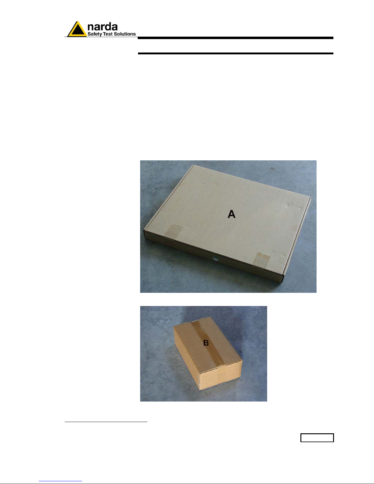
Packaging Instructions 5-1
5 – Packaging Instructions
5.1 Introduction
This section provides the information useful for a correct packaging in case
the unit has to be returned for service to the factory or whenever you need
to prepare the AMS-8061 unit for shipment.
The station should be disassembled stepping back the installation
procedure included in section 2.
The unit includes parts that are sensitive to mechanical shocks as well as
heavy ones like the power pack. It is therefore suggested to follow carefully
the packing instructions to avoid damages due to the shipment.
The following instruction provide several picture useful to identify the
various boxes of the original packaging and their use.
5.2 Packaging
instructions
Box A contains the solar panel.
Box B contains accessories
1
Document AMS8061EN-81008 -1.22 - © NARDA 2018
Page 98
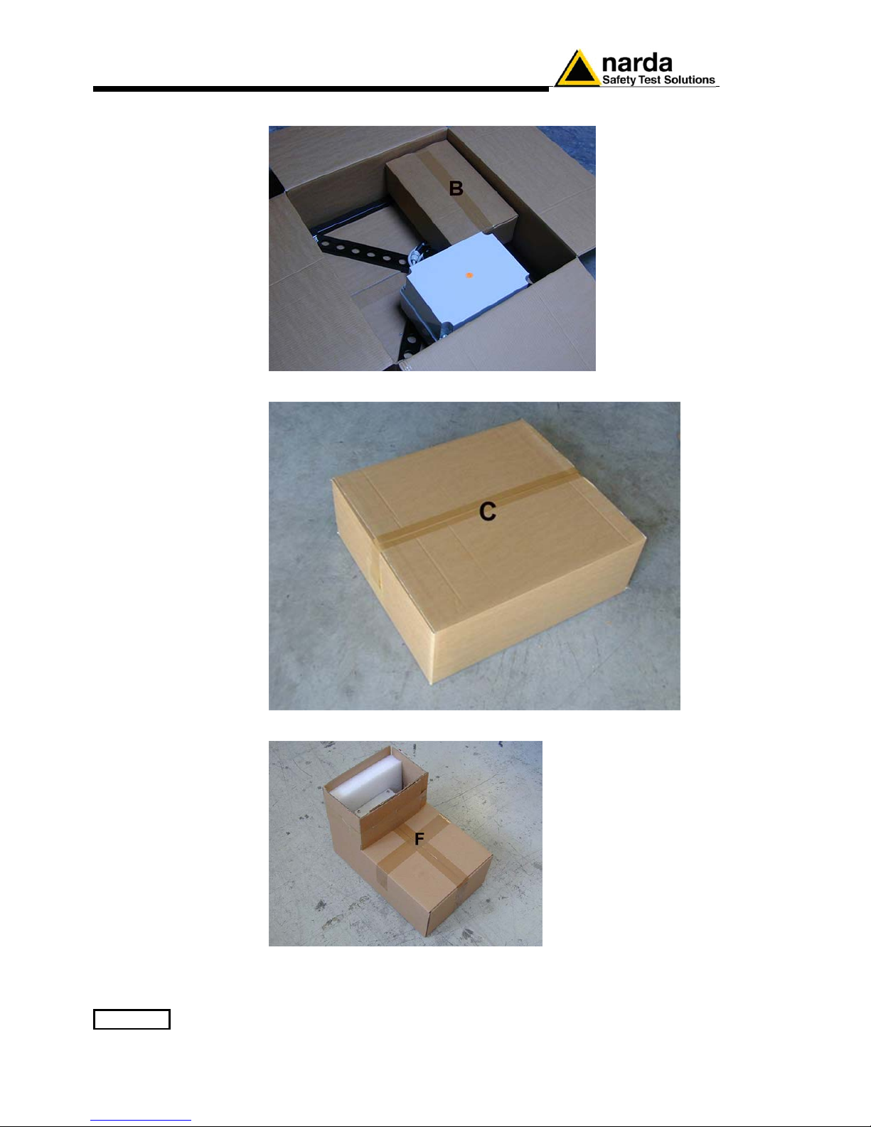
5-2 Packaging Instructions
Box C inside view
Box C contains power pack and box B
Box F contains the receiver unit
Page 99
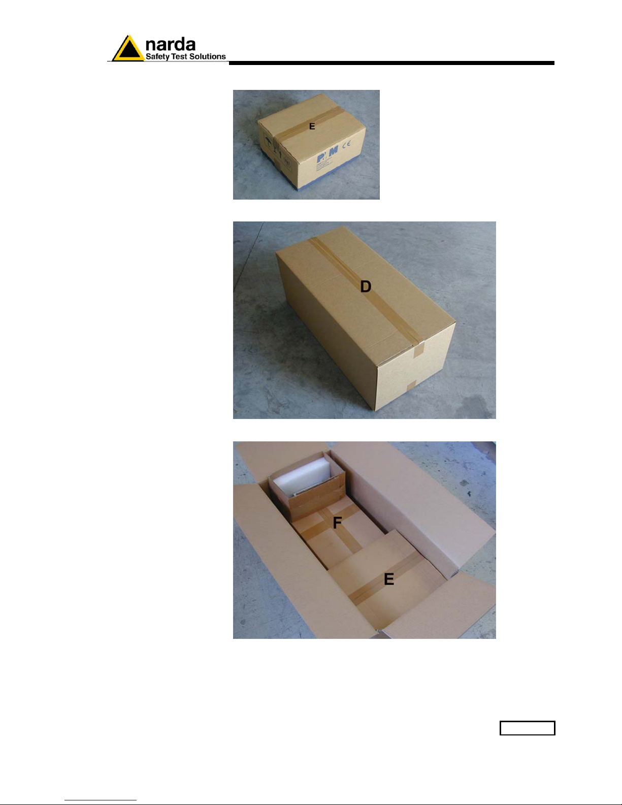
Packaging Instructions 5-3
Box E contains antenna
Box D contains box F and box E
Box D inside view
Page 100
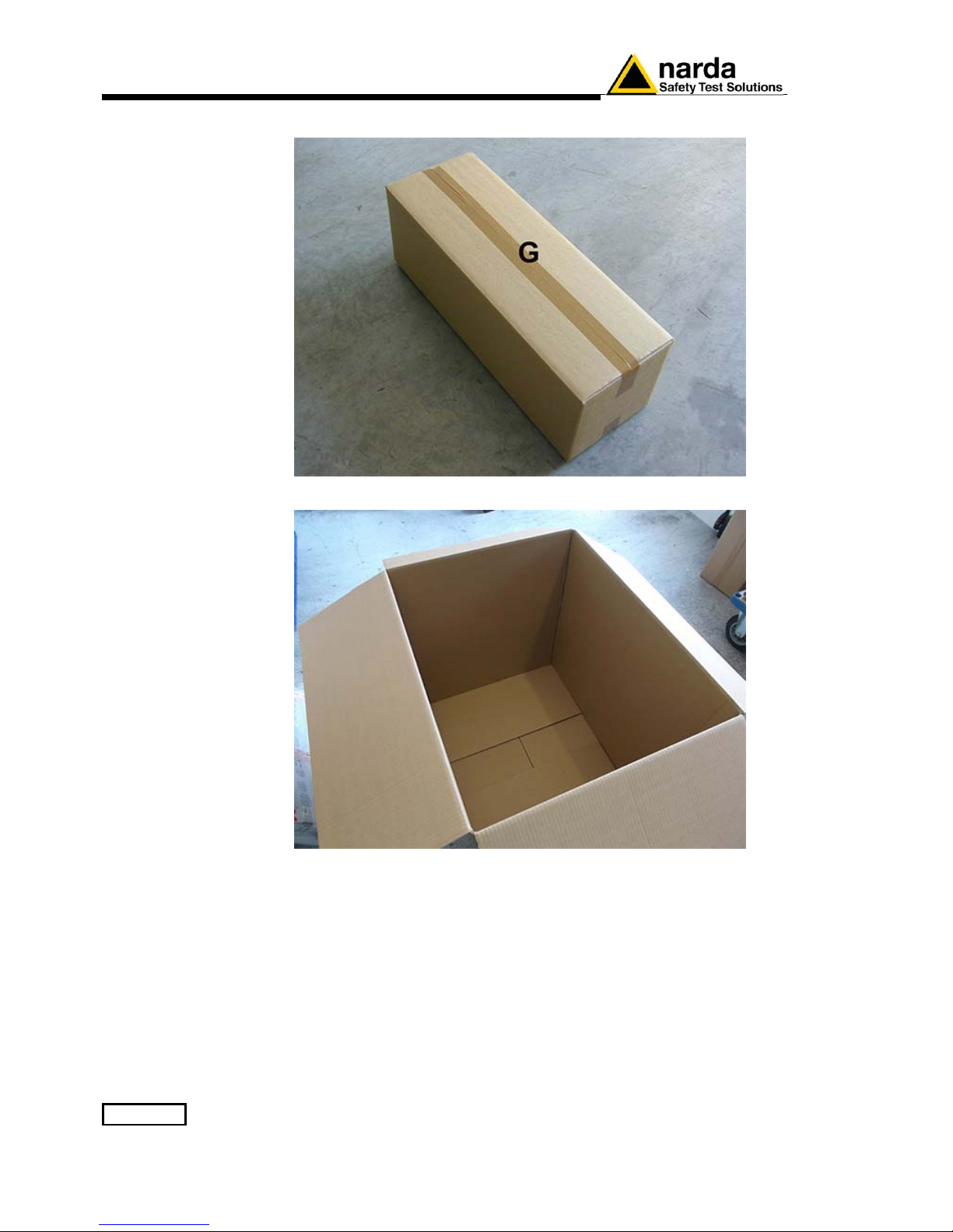
5-4 Packaging Instructions
Box G contains radome
Box H (main box)
 Loading...