


Getting Started
with your 8718
This Getting Started Guide is a
duplication made as a reference and
convenience to our customers who
have misplaced the original (printed in
1996) that came with their 8718 RF
Radiation Survey Meter.
Narda’s logo and contact information
has been updated to enable you to
contact us as needed.
narda
Safety Test Solutions
an communications company
3
L

Table of Contents
Section Name................Pg
1 Introduction ............ 3
2 Description ............. 5
3 Getting Ready ...........11
4 Making a Measurement ......13
5 Menu System ...........29
Index ................33
2

1
Introduction
About the Model 8718
Your Model 8718 is a hand-held, battery-powered
meter designed to simplify the measurement of
electromagnetic fields. It can be used with any
Narda 8700 Series probe.
The meter enables you to perform both simple
measurements and more demanding ones that
require averaging and/or data logging. It can be
mounted on a tripod and used with optional fiber
optic links for enhanced accuracy in certain
applications.
This manual will help you as you begin using your Model 8718.
Equipment Supplied
Your Model 8718 is supplied with:
•
Meter
•
Battery Charger/Power Supply
•
Power Cord (220 volt chargers only)
•
Storage Case
•
Interface Software
•
Operation and Maintenance Manual
•
Getting Started Book
3

4

2
Understanding Your Model 8718
General Description
It is important to be familiar with the Model 8718 before you
use it. This section includes descriptive data keyed to
highlighted illustrations to help you locate the various features
of the meter. The descriptions not only identify the features but
tell you how they are used.
Battery Charger and Power Cord
The battery charger and power cord are used to recharge the
battery within the Model 8718.
To recharge the meter, first connect the cable of
the battery charger to the larger jack on the left
side of the meter. Make sure the plug is fully
inserted into the jack (there are two "stops").
Connect the power cord to the wall outlet.
The battery will be fully charged in about 8 hours.
A full charge will give you about 40 hours of
operation (approximately 8 hours if back lighting
is used).
The charger can also be used to power the
Model 8718 when it is to be operated for periods
beyond the capacity of the battery.
5

Probe Connection
To make measurements, use your Model 8718 with
a probe. Connect the cable of the probe to the
probe connector located at the top of the unit.
If you use a fiber optic link, the probe connects to a
fiber optic transmitter. A fiber optic cable connects
the transmitter to the rectangular fiber optic jack on
the left side of the meter.
Audio Alarm
Your Model 8718 is equipped with an audible alarm
that emits sound through a tiny hole on the bottom
of the meter. The alarm sounds whenever the field
strength exceeds the measurement range of the
probe (over ranges).
You can also set the meter to sound its alarm at a
specific level and/or turn on a variable-tone mode.
Probe Test Sources
Your Model 8718 is equipped with two RF sources
for testing your probes. The Test Source key will
turn these sources on. They will stay on for
approximately 20 seconds.
A microwave (waveguide) window on the right side
of the probe is used for testing high frequency
probes.
A contact on the right side of the meter is used for
testing low frequency probes. These probes have
three test points on the head of the probe.
6

Strap and Tripod Mount
A strap is provided on the underside of the Model
8718. It has a hook and loop closure to permit easy
adjustment, around your hand.
Behind the strap is a threaded connector used to
secure the meter to a tripod. Loosen the strap to
access this connector.
Operation With a Computer
To update probe calibration information or retrieve
stored measurements, you must connect your
Model 8718 to a personal computer and use the
Interface Software provided by Narda.
Refer to the Operation and Maintenance Manual for
detailed information regarding computer operations.
Operation With a Recorder
To obtain a continuous record of measurement
over an extended period of time, you can connect a
data recorder to the smaller jack located on the left
side of the meter.
7

Keyboard
The Model 8718 has four groups of keys distinguished by their
color.
Function keys (green)
Numeric keys (yellow)
Special Function keys (white)
Power keys (blue, green)
Power Keys
Two power keys are used to turn the Model
8718 On and Off.
8
Function Keys
Use the four function keys (F1-F4) to select
the options displayed on the bottom line of
the display screen directly above the F1,
F2, F3, and F4 markings. In a few cases the
options will be spelled out on the display.

Numeric Keypad
Use the numeric keypad to enter number data into the Model
8718. You also use the numeric keypad to select an option listed
on the display screen.
Special Function Keys
Six special function keys enable you to perform specific
functions.
Esc Returns you to the previous menu. In a few
cases you must enter a selection rather than
use the Esc key.
Auto Enables you to automatically zero the meter
Zero and probe.
Help Displays a help screen that explains your options.
Test Turns on the built-in low frequency and high
Source frequency probe test sources for approximately
20 seconds.
Range Locks in a specific measurement range for the
bar graph. The digital display is not affected. The
meter automatically displays a digital value over
the probe’s entire measurement range. See Bar
Graph Ranges on page 21.
Enter Stores data you entered with the numeric
keypad. Confirms an option you selected from
a menu screen.
9

10

3
Getting Ready
Introduction
This section will help you get ready to take measurements with
your Model 8718. Information is included for selecting a probe,
connecting the probe to your Model 8718, and connecting the
optional fiber optic link.
Probe Selection
If you have more than one Series 8700 probe, select the probe
best suited for your task. Factors that you should consider:
FREQUENCY
RANGE
POWER
DENSITY
or FIELD
STRENGTH
ELECTRIC
FIELD or
MAGNETIC
FIELD
FLAT
RESPONSE
or SHAPED
FREQUENCY
RESPONSE
The probe frequency range should include the frequencies of all
the emitters to be surveyed at one time.
The measurement range of the probe should be adequate for
the field levels that you anticipate (i.e., do you expect strong
fields or weak fields?).
Most standards recommend that you measure both electric (E)
and magnetic (H) fields below 300 MHz.
Flat response probes are the most common. Narda’s patented
shaped probes read out in Percent of Standard and are
particularly useful in complex, multi-signal environments where
the exposure limits are different for the various emitter
frequencies.
11

Note
Connecting a Probe
Connect the cable of your probe to the probe connector at the
top of your Model 8718. Make certain that the retaining ring of
the connector is securely fastened.
Using a Fiber Optic Link (optional)
A fiber optic link is useful when remote or low frequency
(<30 MHz) readings are to be made with your Model 8718.
To use the fiber optic link...
1. Connect the probe to the fiber optic transmitter and
make certain that the connector retaining ring is
securely fastened.
2. Connect one end of the fiber optic cable to the fiber
optic transmitter and the other end to the rectangular
fiber optic jack on the left side of the meter.
The meter will
remain set to use the
same input (fiber
optic receiver or
cable), even if you
turn the meter off,
until you use the
menu system to
change the input.
3. Turn the meter ON and press F4 to access the menu
system. Press 8 (NEXT) to get to the second menu
screen. Select CABLE/FO (press 1).
4. If the screen shows that the fiber optic receiver is
turned on, you are ready to proceed. If the screen
shows that the fiber optic receiver is turned off, press
F1 (ON).
5. Press Esc twice to return to the opening menu screen.
6. Press F1 to select a probe and begin the measurement
process.
.
12

4
Making a Measurement
Introduction
This section will help you take measurements with your Model
8718. Information is included for turning the meter on, selecting,
zeroing, and testing a probe, plus an explanation of the main
measurement screen of the meter. Some general information is
also included about measurement surveys, precautions you
should observe, and the use of probe correction factors.
Getting Started
Press the ON power key. After a few seconds, the display
screen will show the meter's calibration date and tell you to
CONNECT PROBE NOW.
To Make Measurements...
1. Select the probe you want to use and connect it to
the meter.
2. Press F1 and proceed to enter the probe model
number
To access the meter’s menu system to perform some other
function...
1. Press F4. The first of three menu screens will appear.
See Section 5, Menu System, for details on features
and operation.
13

Entering the Probe Model
Narda's 8700 Series system is completely modular — all 8700
meters work with all 8700 probes. The single most important
thing you must do is "tell" the 8718 meter which probe you
are using.
The Model 8718 has the basic characteristics of every 8700
Series probe stored in its internal memory. All you have to do is
select the correct model number and the meter automatically
sets the correct scales.
The Model 8718 can also store the specific calibration details
for up to six probes. This includes the probe serial number,
calibration date, and the calibration factors marked on the
handle of the probe. Probes with this additional detail stored in
the meter are referred to as probes in memory.
Putting probes into memory has several advantages:
It makes it easier to select a probe
•
Data that is downloaded after using a data logging mode
•
will include a record of the probe’s calibration date and
its serial number.
•
It makes using frequency correction much easier.
Probes are put into the meter’s memory using a personal
computer:
•
By Narda on the day of shipment for all probes shipped
at the same time as the meter.
•
By you at any time when you use the Interface Software
supplied by Narda and a personal computer. Refer to
Operation and Maintenance Manual for detailed
information regarding computer operations.
14

To select from the PROBES IN MEMORY...
1. If you haven’t already, press F1 (MEASURE).
2. The model number and the serial number of the last
probe used will be displayed on the second line of the
display. If you want to use the same probe, press
Enter.
SELECT PROBE
MODEL A8722 SND XXXXX
OR SEL ECT FROM L I S T
87XX 87XX 87XX MORE
F1 F2 F3 F4
3. If you want to use a different probe, look for the model
number in the positions above the F1, F2, or F3
legends. Up to three additional models can be found
by pressing F4 (MORE).
4. Press the appropriate function key and the probe
model and serial number will be displayed on the
second line of the screen. If this is correct, press Enter.
5. A new screen will appear specifying probe model
number, serial number, frequency range, field type,
maximum measurement range, and type of response
(flat or shaped). If this information is correct, press F1.
If this information does not match your requirements,
you need to select another probe. Press F2 and you
will go back to the Select Probe Screen to make
another selection.
A8742D S/N 00001
300 H -3GHzzkE-FLD
600 % STD SHAPED
YES NO MENU
F1 F2 F3 F4
6. Proceed with the probe zeroing process.
15

To use a PROBE that is NOT IN MEMORY...
1. If you haven't already, press F1 (MEASURE).
2. The model number of the last probe used will be
displayed on the second line of the display. If you want
to use the same model probe, press Enter.
SELECT PROBE
MODEL A8722 SND XXXXX
OR SELECT FROM L I ST
87XX 87XX 87XX PROBE
F1 F2 F3 F4
3. If you want to use a different model probe, select
PROBE by pressing F4. If more than three probes are in
memory, you will have to press F4 twice (MORE, then
PROBE). One of three screens that list all 8700 model
probes will appear.
Note
You must turn off the
meter and repeat the
probe selection and
zeroing process if
you want to change
probes.
1 A8722D 5 A8732D
2 B8722D 6 A8742D
3 C8722D
4 D8722D 8 NEXT
F1 F2 F3 F4
4. If you see the model of the probe you want to use, press
the appropriate number key.
5. If you do not see the model number you want, use the
F1 and F2 keys to page forward and backward until you
do. Press the appropriate number key.
6. A new screen will appear specifying probe model
number, frequency range, field type, maximum
measurement range, and type of response (flat or
shaped). If this information is correct, press F1. If this
information does not match your requirements you need
to select another probe. Press F2 and you will go back
to the Select Probe Screen to make another selection.
7. Proceed with the probe zeroing process.
16

A8722D SNXXXXX
300 H - 50GHzzkE-FLD
300 % STD SHAPED
YES NO MENU
F1 F2 F3 F4
Zeroing the Probe
The probe and meter must be “zeroed” together. It is important
that the probe is not exposed to radiated fields during the
zeroing process. The storage case is shielded and provides a
convenient “zero density” environment.
To zero the probe...
Note
Position the probe in
the case with one
test point pointed
downward and the
other two test points
above the foam.
This will insure that
the test points are
not touching the
foam.
1. Place the probe in the storage case. Be careful not
to move the probe while zeroing takes place (on
probes with low frequency test points, you can create
static which will give inaccurate results).
2. When you are ready, press the ENTER key. The
screen will say ZEROING...
3. After zeroing is completed, the main measurement
screen will appear.
If you get a message that the probe could not be zeroed, the
most likely causes are:
•
The probe is not connected properly. Check the
connector and retry.
•
The meter is set for a fiber optic input and you are
using the standard cable input (or vice versa). Turn the
meter off. Turn the meter back on and press
(F4) to access the menu system. Press
8 (NEXT) to get to the Second Menu Screen. Select
CABLE/FO (press 1). Check the CABLE/FO setting to
make sure the fiber optic receiver input (FO) is turned
on. If the screen shows that the fiber optic receiver is
turned off, press F1 (ON) to enable it. Then press Esc
twice to return to the Opening Menu Screen.
17

The field strength is not low enough. Move away from
•
the antenna and use the storage case to zero the probe.
The probe is damaged. Try another probe.
•
To reconfirm the zero while the instrument is in use...
1. Establish a zero density environment for the probe as
before.
2. Press the Auto Zero key. This will automatically “touch
up” the zero and correct for any drift in about 10
seconds.
18

Measurement Display Screen
The Main Measurement Display Screen shows a maximum
value on the third line of the display. The Alternate Measurement
Display Screen provides frequency-specific, real time information
instead of a maximum value.
Main Measurement Display Screen
(Shaped Probes)
MAXIMUM VALUE
• Indicates the
maximum value that
has occurred since
you began making
measurements or
since resetting the
maximum.
• The unit of measure is
the same as for the
instantaneous value
shown on the line
above.
BAR GRAPH
Indicates approximate
•
field strength
100 segment, three
•
10:1 (10 dB) ranges
12.1 % STD
27.5 MAX CF 1.00
LOG MENU %STD FREQ
F1 F2 F3 F4
F1
(LOG) instantly
logs the current
value
F2
Switches you to
the first screen of
the menu system.
The menu system
allows you to set
operating
parameters for the
Model 8718
F4
Allows you to enter
or change the
frequency that you
are correcting for
probe frequency
deviation
F3
Toggles the third line of the display
between a maximum value and an
instantaneous percent of standard
(see Alternate Display Screen). If
you have entered a frequency, you
will switch to the Alternate Display
Screen. You will also reset the
maximum value at the same time. If
you have not entered a frequency
you will reset the maximum value
and the main measurement display
screen will remain.
FIELD STRENGTH
Indicates actual measured value
•
Unit of measure is always % STD
•
for shaped frequency response
probes
PROBE FREQUENCY
CORRECTION
• CF = 1.00 indicates
no correction factor is
being applied
• CF= X.XX indicates
the numeric value that
is being applied
• A frequency displayed
here indicates that the
meter is applying a
correction factor
based on the stored
calibration data for the
specific probe in use.
19

CALCULATED
PERCENT OF
STANDARD
Displays percent of
•
standard that has been
calculated from the
field strength reading
using the referenced
standard and the
indicated frequency
Alternate Display Screen
The Alternate Display Screen is very similar to the Main
Measurement Display Screen with one difference. On the third
line an instantaneous indication of the percent of standard is
shown instead of displaying a maximum value. This screen
should only be used with flat response probes for single
frequency measurements or where all the emitter frequencies
are close and the standard has the same limits.
.26 Wmmc/
6
125 . 2% STD 10 . 00 HzG
LOG MENU MAX FREQ
2
F1 F2 F3 F4
FIELD STRENGTH
Indicates actual
•
measured value
Unit of measure can be
•
changed by going to the
First Menu Screen
To use the Alternate Display Screen...
1. Press F4 (FREQ) and then enter the frequency that
you are measuring. You must fill all four positions. Use
F1, F2,orF3 as required to change the units.
2. Press F4 (SAVE). The probe correction factor will be
displayed briefly if you are using a probe in memory
and you will return to the main measurement screen.
3. Press F2 (MENU), then 8 (NEXT) to access the
second menu screen. Select STNDS (6). Press the
appropriate standard that you want to reference. (You
must use a function key even if the current setting is
correct.) A new screen will appear.
4. Press F1 to verify or F4 to make another selection.
Press Esc twice to go back to the main measurement
screen.
5. From the Main Measurement Screen select %STD by
pressing F3. The meter will now automatically display
the instantaneous measured value in the chosen units
on the second line and at the same time compare that
20

value to the standard at the frequency shown on line 3.
This instantaneous readout of percent of standard is
particularly useful where the allowable level must
normally be calculated. If you are using a probe in
memory or have entered a numeric correction factor,
the meter will also be correcting for probe frequency
deviation.
6. Note that pressing F3 also clears the maximum value
from the meter's memory.
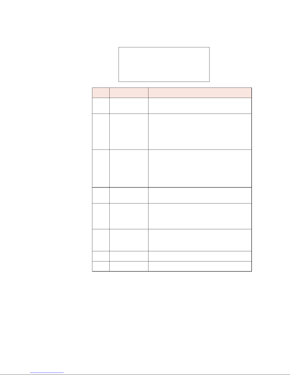
Bar Graph Ranges
The Range key is used to control how the bar graph displays
information. The digital display is not affected and the meter
automatically displays a digital value over the probe’s entire
measurement range. There are four available settings: AUTO,
HIGH, MID, and LOW. The bar graph has 100 divisions.
Note
The Range Key only
affects how the bar
graph displays
information.
You will probably find it convenient to use the AUTO setting
most of the time, but under a few conditions you may find one of
the three fixed ranges useful. The following table illustrates how
the range setting will affect the bar graph. For simplicity, a
probe with a full scale rating of 100 mW/cm
2
is used as an
example.
Range Measurement Range
AUTO As the level increases the bar graph
automatically switches between three ranges:
0.01 to 1, 1 to 10, and 10 to 100.
HIGH 1to100
MID 0.1 to 10
LOW 0.01 to 1
If you exceed the upper limit of either the MID or LOW range, the
bar graph will be replaced with the message RANGE
OVERLOAD. The digital display will continue to show the
correct value.
21

Using Audio Alarms
You can set an audio alarm to sound at a specific value. You can
also activate a variable tone alarm. Both alarms can help you
conduct surveys and can provide a warning of high
electromagnetic fields. You can even use both at the same time.
Under these conditions, the variable tone alarm will change with
the field strength unless the threshold you specified is
exceeded. At this point the continuous tone of the fixed alarm
takes over.
To use the fixed audio alarm...
1. From either measurement screen, press F2 (MENU),
then 7 (AUDIO).
2. Set the alarm level by entering a two digit number
using the numeric keys. This number is equal to the
percentage of full scale rating of the probe that you are
using. For example, if you are using a probe rated at 20
2
mW/cm
mW/cm
and you enter 35, the alarm will sound at 7
2
(35% of 20).
3. Press Enter.
4. Press F1 to turn the fixed alarm ON.
5. Press Esc twice to return to the measurement screen
To use the variable alarm...
1. From either measurement screen, press F2 (MENU),
than 7 (Audio).
2. Press F3 to turn the variable alarm ON.
3. Press Esc twice to return to the measurement screen.
The audio alarm will increase its repetition rate in response to
the intensity of the field being measured. Note that the variable
alarm corresponds to the bar graph. It may be desirable to use
the Range key to select a fixed range setting (see Bar Graph
Ranges on page 21).
22

Testing the Probe
Your Model 8718 is equipped with two RF sources for testing
probes. Press Test Source and both sources will stay on for
approximately 20 seconds.
A contact on the right side of the unit is used for testing low
frequency probes. These probes have three test points around
the head of the probe. Position the probe so that one of the test
points touches the contact on the meter. You should get a
deflection on the bar graph but the amount of deflection is not
important. Repeat for the other two test points to insure that the
probe is working correctly.
A microwave window on the right side of the probe is used for
testing high frequency probes. Hold the probe parallel to the
right side of the meter and position the probe head against the
test window so that one of three arrows on the probe is pointing
towards the window. These arrows indicate the location of the
three sensors inside the probe. A deflection of any magnitude
on the bar graph is acceptable. Repeat for the other two sensors
to insure that the probe is working correctly.
Ultra-broadband probes contain both high frequency and low
frequency sensors. These probes require six checks – three
high frequency and three low frequency.
Using Probe Correction Factors
All probes have a certain amount of frequency sensitivity.
Frequency sensitivity is the amount of deviation from the correct
measured value that a probe yields at various frequencies.
Obviously, the smaller the deviation, the better. But since a
certain amount of frequency deviation is unavoidable, the more
frequencies that you calibrate the probe at, the better. At each
calibration frequency, you have a correction factor.
Multiplying the reading on the meter by a correction factor
marked on the handle of a Narda 8700 Series probe
compensates for the probe’s frequency sensitivity. The Model
8718 is unique because it can perform this task automatically.
23

Correction factors can be used:
When there is only a single emitter being surveyed.
•
When there are multiple emitters all operating at the
•
same frequency (this is often the case with industrial
equipment).
When there are multiple emitters with frequencies that
•
are close to each other and the nearest calibration
frequencies have very similar correction factors.
Correction factors should NOT be used:
When the frequencies of the emitters are diverse.
•
Correction factors may vary considerably and there is no
way to determine the distribution of energy from the
various emitters. It is more accurate not to use a
correction factor under these conditions. See
Measurement Uncertainty on page 26.
To use a correction factor for a probe in memory...
1. Press F4 (FREQ) from the measurement screen. A
new screen will appear to allow you to enter a
frequency.
2. Enter the frequency for which you want to correct for.
Make sure you fill in all four positions. If you make a
mistake just enter more digits until correct. For greater
accuracy, use the units that allow the larger
numbers. For example, enter 10 kHz, not 00.01 MHz.
3. Change the units (if needed) by pressing either
F1 (kHz), F2 (MHz), or F3 (GHz).
4. Press F4 (SAVE). The meter will automatically
calculate the correction factor for the frequency you
have entered from the two closest correction factors
that were stored when you put the probe in memory.
The calculated numeric value will be displayed briefly
before the meter automatically returns to the
measurement screen.
5. The frequency that you are correcting for will be
displayed on the right side of the third line of the
display.
24

To use a correction factor for a probe NOT in memory...
1. Press F2 (MENU). The First Menu Screen will appear.
2. Press 3 (COR FACT). A screen will appear that shows
the correction factor.
3. Use the correction factors on the handle of the probe
to determine the appropriate correction factor and then
use the numeric keys on the meter to enter this value.
Enter a three digit number, ignoring the decimal point,
and rounding to two digits to the right of the decimal
point. If you make a mistake, just enter more digits
until correct. For example, to enter a correction factor
of 1.22, simply enter 1, 2, and then 2 while a correction
factor of 0.94 is entered as 0, 9, and 4.
5. Press Enter to save this correction factor. The meter
automatically returns to the measurement screen.
6. The numeric correction factor will be displayed on
the right side of the third line of the display in the form
CF X.XX.
25

Measurement Uncertainty
The uncertainty of any measurement includes several factors:
Frequency response or frequency sensitivity is typically
•
±1 dB to ±2 dB (from about ±25% to about ±55%).
The correct use of correction factors can greatly reduce
the amount of uncertainty associated with frequency
response.
Ellipse ratio is ±0.75 dB or better, depending on the
•
model of the probe. The ellipse ratio is the ratio of
readings that occur when one rotates the probe around
the axis of its handle. Narda calibrates its probes by
rotating the probe about its axis and using the mean
value to determine the correction factor. If you rotate
the probe around its axis and use the mean value,
ellipse ratio can be eliminated as a source of uncertainty.
Isotropic response is the error that occurs when the
•
probe is pointed in different directions. It includes the
ellipse ratio plus some additional uncertainties.
Although the probes pick up energy from all directions,
they are most accurate when pointed at the source of
energy. Generally speaking, the isotropic response is
no greater than the ellipse ratio providing that the probe
is pointed towards the source.
26
•
Calibration uncertainty represents another 0.5 dB.
•
The Model 8718 meter is accurate within ±3%.
A good rule of thumb is that the total uncertainty is no greater
than ±3 dB when correction factors are not used, providing
that the probe is pointed at the source of energy.

Obtaining a Reading
A reading is obtained by holding your Model 8718 in one hand
and your probe in the other. As you approach the source,
observe the bar graph and measured value of signal strength
on your meter. If you know where the source of energy is, point
the probe towards it. If you do not know where the source is
located or there are multiple sources, hold the probe above
your head pointed up at about 45 degrees above the
horizontal. Rotate the probe in a circle to find the direction
where the maximum indication is obtained. The bar graph is a
useful tool in obtaining the maximum indication.
About Measurement Surveys
When you perform surveys, it is important that you observe a
few guidelines to insure accurate readings:
Make sure you move the probe to obtain a maximum
•
reading.
Keep the arm holding the probe extended out from your
•
body as far as possible with the probe pointed towards
the source of radiation.
•
Low frequency measurements (<50 MHz and especially
<10 MHz) require special techniques because the
human body acts as an antenna and introduces errors.
Using the best technique, place the probe next to the
meter on a non metallic stand such as a wooden ladder
or cardboard box. Stand back and read the meter
without touching it.
The human body has far less affect on magnetic fields and
therefore these measurement techniques are less critical for
magnetic fields than they are for electric fields.
Refer to the operations manual for more complete information
on planning, conducting, and documenting measurement
surveys.
27

Precautions
When making measurements of electromagnetic fields, a
potential exists to expose yourself to excessive levels.
Approach the source of energy slowly and begin making
measurements from a distance at which low field levels exist.
Be prepared to evacuate the area immediately if RF field levels
in excess of the applicable standard are observed.
28

5
Using the Menu System
Introduction
This section will help you use the Model 8718's menu system.
The menu system allows you to enter and store data and to
select various options during operation.
The menu system is always available from any measurement
mode. It is accessed by pressing the appropriate function key
that corresponds to MENU on the bottom line of the display
screen.
The menu system is comprised of three menu screens where all
the basic options are listed. A specific menu item is selected by
pressing the appropriate numeric key that corresponds with that
menu item. Instructions or sub menus appear when one of the
basic menu options is selected. If it isn't clear what to do, press
the Help key.
29

First Menu Screen
1=SETUPS 5=PROBE
2=DISPLAY AV 6=UNITS
3=CORR FACT 7=AUDIO
4=BAT TEST 8=NEXT
Key Menu Options
Up to four sets of measurement situations
can be stored and recalled. Setups are
1
DISPLAY AVG
2
SETUPS
similar to macros in other computer
programs and can save keystrokes when
repeating measurements with the same
meter settings.
Select from four options to determine how
fast the digital information is updated on
the screen.
3
4
5
6
7
COR FACT Enter a numeric correction factor.
Check battery charge status and
estimated use time remaining.
BAT TST
PROBE
UNITS
AUDIO
Turn the back light on or off using F3.
Adjust display contrast (Press Help for
instructions).
Show the model and serial number of the
probe in use.
Select the measurement range when
using Models 8782 and E8782 probes.
Select from all appropriate units of
measure (i.e., mW/cm
the probe in use. Percent of Standard is
the only unit of measure for shaped
probes.
Turn the audio alarm on or off.
Set the alarm threshold in terms of
percent of full scale of the probe in use
(1% to 99%).
Turn the variable tone alarm on or off.
2
, V/m, V2/m2) for
8 NEXT
30
Go to the Second Menu Screen.
Second Menu Screen
1=CABLE/FO 5=RS232
2=TIME AVG 6=STDS
3=DATA LOG 7=BACK
4=TIME SET 8=NEXT
Key Menu Options
1 CABLE/FO
2 TIME AVG
3 DATA LOG
4 TIME SET
5 RS232
6
STNDS
Select between the standard probe cable
input and the fiber optic receiver.
Turn fixed time averaging (various
duration) on or off.
Turn the spatial averaging mode (used for
whole body averaging measurements) on
or off.
Log with time and date stamp.
Log with time and date stamp plus
reference number.
Continuous logging at various specific
rates.
Check or set the meter's internal clock
(time/date).
Turn the RS232 port on or off.
Default is off.
Change the baud rate.
Check or set the standard that is
referenced for various measurement
options.
7
8 NEXT Go to the Third Menu Screen.
BACK
Return to the first menu screen.
31

Third Menu Screen
1=LOCKOUT 3=BACK
2=BLANKOUT
The three menu items provide these options:
Key Menu Options
Lock the keypad so that settings will not
1 LOCKOUT
2 BLANKOUT
3 BACK Return to the Second Menu Screen.
Future firmware options will be added to this screen.
accidentally change. To release, press
ENTER and ESC together.
Blank the display and lock the keypad. To
release, press ENTER and ESC together
and then select another menu item.
32

INDEX
Alarm, Audio
Description .................................................6
Using ........................................................22
AUDIO, menu .............................................30
Auto Zero, key..............................................9
BACK, menu...............................................32
Bar Graph Ranges ......................................21
BAT TST, menu ..........................................30
Battery Charger.............................................5
BLANK OUT, menu ....................................32
CABLE/FO, menu.......................................31
Computer Operation .....................................7
COR FACT, menu ......................................30
Correction Factors, Probe ..........................24
DATA LOG, menu.......................................31
Description, 8718 ..........................................3
DISPLAY AVG, menu .................................30
Display Screen
Alternate ...................................................20
Main..........................................................19
Electric Field................................................11
Enter, key......................................................9
Equipment.....................................................3
ESC, key .......................................................9
F1 through F4, keys.......................................8
Fiber Optic Link, use with ............................12
Field Strength..............................................11
Flat Response .............................................11
Frequency Range .......................................11
Help, key.......................................................9
Keyboard.......................................................8
Keys
Function .....................................................8
Numeric......................................................9
Power .........................................................8
Special Function.........................................9
Magnetic Field.............................................11
Measurements
Making a Measurement ............................13
Precautions ..............................................28
Uncertainty ...............................................26
Menu Screen
First...........................................................30
Second .....................................................31
Third .........................................................32
Menu System ..............................................29
Off, key..........................................................8
On, key..........................................................8
Power Cord ...................................................5
Power Density .............................................11
Power Keys ...................................................8
Precautions .................................................28
Probe
Connection ...........................................6, 12
Correction Factors....................................23
Entering Model .........................................14
Selection ...................................................11
Test Sources ...............................................6
Testing ......................................................23
Zeroing......................................................17
PROBE, menu ............................................30
Range, key....................................................9
Ranges, Bar Graph .....................................21
Recorder Output ...........................................7
RS232, menu ..............................................31
SETUPS, menu...........................................30
Shaped Response ......................................11
STNDS, menu.............................................31
Strap..............................................................7
Surveys
Measurements..........................................27
Obtaining Reading ...................................27
Precautions ..............................................28
Test Source, key ..........................................9
Test Sources .................................................6
TIME AVG ...................................................31
TIME SET....................................................31
Tripod Mount.................................................7
UNITS, menu ..............................................30
Zeroing, probe ............................................17
33

narda
Safety Test Solutions
an communications company
3
L
USA: 435 Moreland Road
Hauppauge, NY 11788
Tel 1-631 231-1700 Fax 1-631 231-1711
E-Mail NardaSTS@L-3COM.com
www.narda-sts.com
GERMANY: Sandwiesenstrasse 7
D-72793 Pfullingen
Tel +49-7121-9732-777 Fax +49-7121-9732-790
E-Mail support@narda-sts.de
www.narda-sts.de
 Loading...