

Page 1

Brain Function Monitor for the Operating Room
and the Intensive Care Unit
(Version ICU)
Operating Instructions
(Software version 3.2)
MT MonitorTechnik GmbH & Co. KG
Maienbass 27
24576 Bad Bramstedt
Germany
Copyright ©, MT MonitorTechnik GmbH & Co. KG. All rights reserved.
This document must not be reproduced, edited or copied without the prior written approval of
MT MonitorTechnik GmbH & Co. KG.
Document: NAT_OperatingInstructions_ICU_US_Rev12, date: 2018-05-25
Page 2

Page 2
• Warning:
The Medical Device Narcotrend is provided for the exclusive use of
qualified physicians or personnel under their direct supervision. The
numerical and graphical results from a recording must be examined
with respect to the patient’s overall clinical condition. The recording
preparation quality and the general recorded data quality, which could
affect the report data accuracy, must also be taken into account.
It is the physician’s responsibility to make the diagnosis or to obtain
expert opinion on the results and to institute correct treatment if
indicated.
• Caution:
Federal law restricts this device to sale by or on the order of a
physician.
Contact:
Narcotrend-Service
Fuhrberger Strasse 4
30625 Hannover
Germany
Phone: +49 (0) 4192 / 201753
Fax: +49 (0) 4192 / 201754
eMail: [email protected]
Web: www.narcotrend.de
Page 3

Page 3
Table of Contents
1 Introduction ........................................................................................................... 5
2 Equipment description .......................................................................................... 6
2.1 Operation ............................................................................................................ 7
2.2 Battery operation ................................................................................................. 7
2.3 USB port .............................................................................................................. 8
2.4 Bluetooth (IEEE 802.15.1) ................................................................................... 8
2.5 IntelliBridge connector (optional) ......................................................................... 9
2.6 RS232 connector ................................................................................................. 9
3 Safety instructions .............................................................................................. 10
4 Putting into operation ......................................................................................... 12
4.1 Device setup...................................................................................................... 12
4.2 Device setup (IntelliBridge (optional)) ................................................................ 12
4.3 Applying the electrodes ..................................................................................... 13
4.4 Start recording / Start screen ............................................................................. 15
4.5 Options / Start screen ........................................................................................ 16
5 Recording screen ................................................................................................ 17
5.1 Title line ............................................................................................................. 17
5.2 EEG .................................................................................................................. 17
5.3 Stage / Index ..................................................................................................... 18
5.4 Additional parameters ........................................................................................ 19
5.4.1 EMG ............................................................................................................. 19
5.4.2 BSR .............................................................................................................. 19
5.4.3 STI ................................................................................................................ 19
5.5 Diagrams ........................................................................................................... 19
5.5.1 Cerebrogram ................................................................................................. 20
5.5.2 Relative Band Activities / Power .................................................................... 20
5.5.3 Quantiles ....................................................................................................... 20
5.5.4 Power Spectrum ........................................................................................... 21
5.5.5 DSA .............................................................................................................. 21
5.6 EEG analysis for children in the first year of life ................................................. 22
5.7 Button bar .......................................................................................................... 23
5.8 Review mode ..................................................................................................... 24
5.9 Electrode settings .............................................................................................. 25
5.10 Marker ............................................................................................................... 26
5.11 Options .............................................................................................................. 27
6 EEG and evaluations (RS232 / IntelliBridge connector) ................................... 28
6.1 EEG .................................................................................................................. 28
6.2 Narcotrend-Index NI .......................................................................................... 28
6.3 Additional parameters ........................................................................................ 29
6.4 Electrode check ................................................................................................. 30
6.5 Error messages ................................................................................................. 30
7 Analyse recording ............................................................................................... 31
7.1 View .................................................................................................................. 33
7.2 Save .................................................................................................................. 35
7.3 Print ................................................................................................................... 35
7.4 Delete ................................................................................................................ 35
Page 4

Page 4
8 Cleaning, maintenance, repair ............................................................................ 36
8.1 Care and cleaning .............................................................................................. 36
8.2 Recommended checks ...................................................................................... 37
8.3 Error messages ................................................................................................. 38
8.4 Battery ............................................................................................................... 40
8.4.1 Checking the battery...................................................................................... 40
8.4.2 Changing the battery ..................................................................................... 40
8.5 Disposal ............................................................................................................. 40
9 Technical data ...................................................................................................... 41
9.1 Symbols ............................................................................................................. 41
9.2 Classification and technical data ........................................................................ 42
9.3 Spare parts and article numbers ........................................................................ 43
9.4 EMC-Guidance .................................................................................................. 44
10 List of figures ....................................................................................................... 47
Page 5
Page 5
1 Introduction
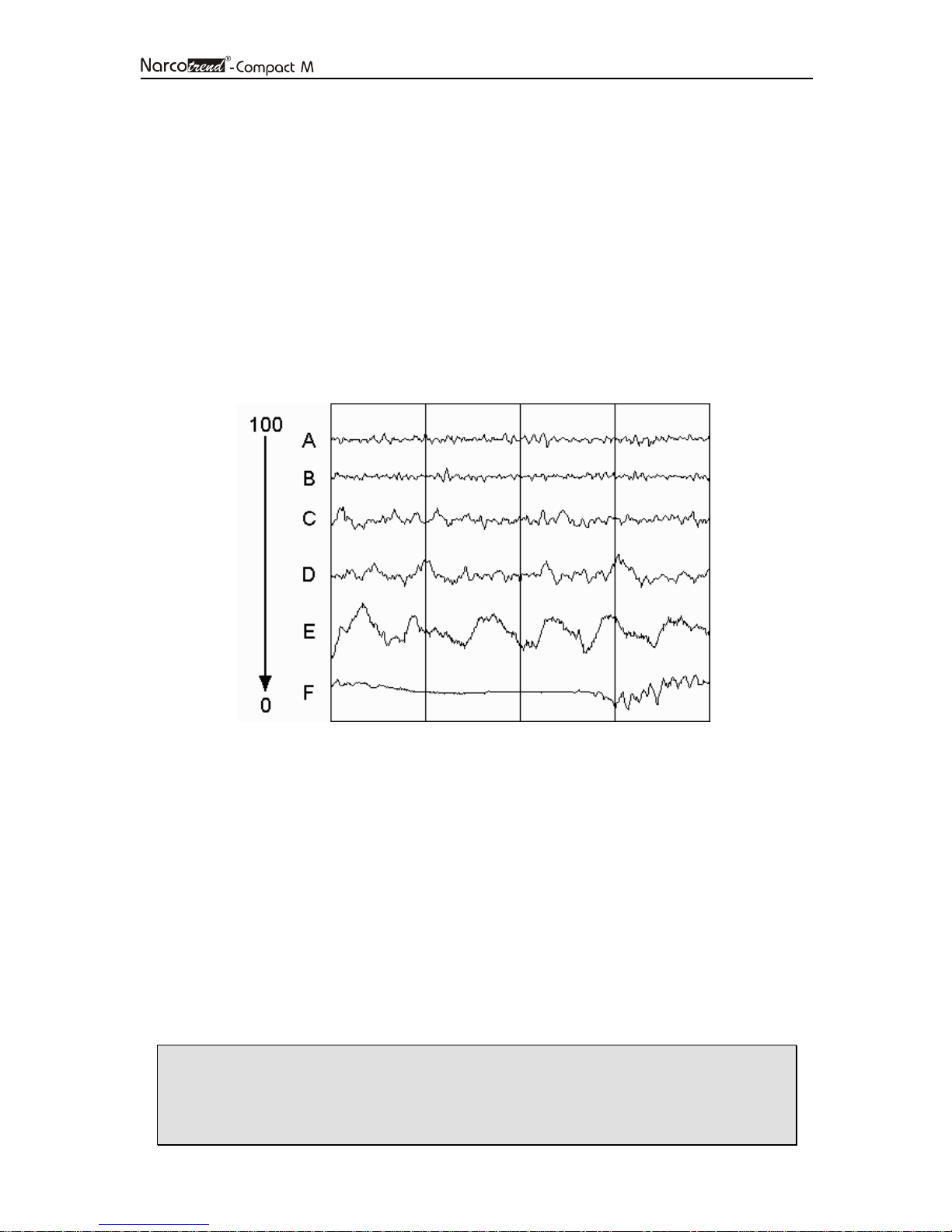
The Narcotrend-Compact M serves the purpose of brain function monitoring and was
developed specifically for use with hypnotically acting drugs in operating rooms,
intensive care units and for clinical research. The Narcotrend-Compact M includes the
Narcotrend-Index, a processed EEG parameter, which may be used as an aid in
monitoring the effects of certain hypnotically acting anesthetic agents.
Under the influence of narcotics/anesthetics, the EEG reveals very characteristic
changes. The EEG can therefore be used to assess the hypnotic status of the patient.
Based on a large number of parameters derived from the EEG, multivariate statistical
methods are used to carry out an automatic classification of the EEG on a scale ranging
from stage A (conscious) to stage F (very deep hypnosis). This division of stages is
refined by means of an EEG index (100 = conscious, 0 = very deep hypnosis).
Fig. 1: EEG index, EEG stages und typical EEG patterns
The automatic classifications in variation of time constitute the cerebrogram. This
cerebrogram provides the user with important information on the hypnotic status of the
patient in the course of the recording.
An impedance check is available in order to ensure good signal quality. During an ongoing recording, the program carries out automatic electrode tests at regular intervals.
In addition, extensive algorithms for automatic detection of artifacts have been
implemented in the program.
• The automatic assessment is not allowed to be the sole criterion of a
narcosis or sedation controlling function. With respect to the dosing of
narcotics and sedatives, the overall clinical findings must be taken into
account.
Page 6
Page 6
2 Equipment description
The Narcotrend consists of the following components:
• Narcotrend-Compact M
• Narcotrend-Compact M - power supply
• Patient lead 1-channel (PKM1)
• Patient lead 2-channel (PKM4) (optional)
• Mounting clamp (optional)
• Use only the original Narcotrend-Compact M - power supply.
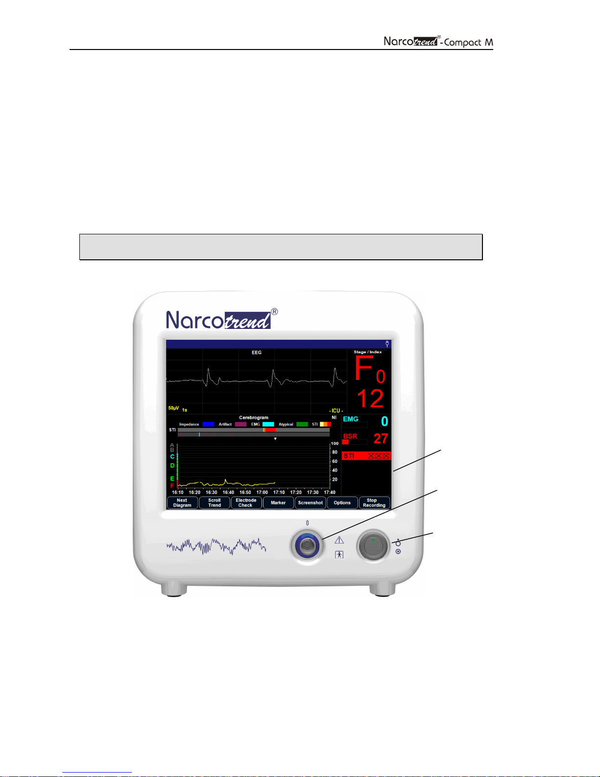
Touchscreen
Interface for
patient lead
On/Off switch
Fig. 2: Narcotrend-Compact M, front panel
Page 7
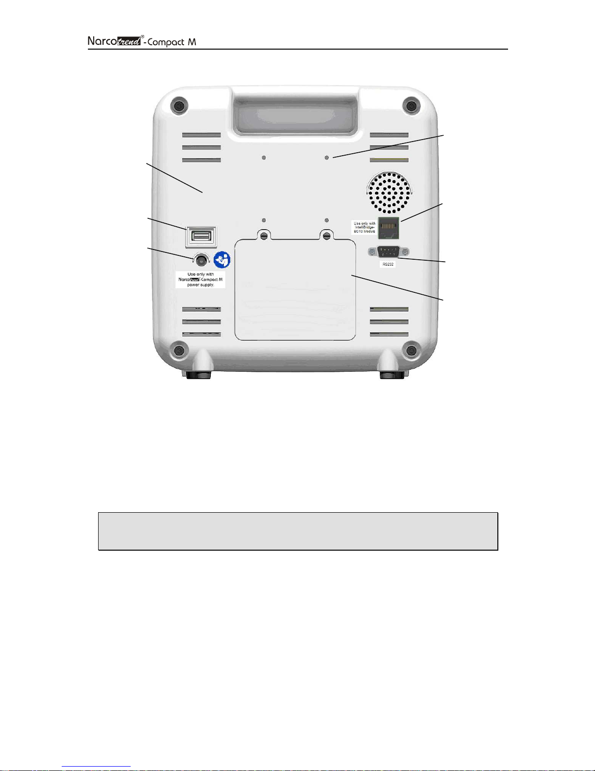
Space for
type plate
USB Port
Page 7
4 holes to affix
Mounting clamp
(VESA 50)
IntelliBridge
connector
(optional)
Connection for
Narcotrend-
Compact M –
Power Supply
Fig. 3: Narcotrend-Compact M, rear panel
2.1 Operation
The device is switched on by pressing the On/Off switch briefly.
The software is operated completely via the integrated touchscreen, i.e. all input
operations are made by touching the screen briefly.
• The touchscreen reacts very sensitively. Please don’t use sharp or
pointed objects like pens or pencils for operation.
RS232
connector
Battery box
To switch off the device use the button Q
2.2 Battery operation
The Narcotrend-Compact M is equipped with an integrated battery that allows the
device to be used for at least 2 hours without being connected to a power supply
system.
The battery charging time is approx. 2 hours when the device is switched off and
approx. 8 hours when the device is switched on.
UIT
on the screen.
Page 8

Page 8
2.3 USB port
The USB 2.0 interface is provided for data backup of EEG measurements and to store
PDF files on USB storage devices. In some cases, USB storage devices are not
detected. To resolve this problem it is recommended to use another USB storage
device.
USB flash drives can be connected.
• The USB port provides 500 mA at 5 V.
• The USB port is used to archive stored recordings on the connected
USB storage media.
2.4 Bluetooth (IEEE 802.15.1)
The integrated Bluetooth interface enables the transmission of EEG signals and
evaluated parameters to store or display the values on a Bluetooth-enabled external
device.
The reception of data from the external device is not provided.
The point-to-point connection enables just one device to connect with the Narcotrend-
Compact M at one time.
Thereby the risk of interference is reduced and the integrity of the data is ensured.
For further information see the document: “NAT_InterfaceSpecification_2017-09-26”.
• This device contains
FCC ID: PVH0946
IC: 5325A-0946
• This device complies with Part 15 of the FCC Rules.
• Operation is subject to the following two conditions;
(1) this device may not cause harmful interference, and
(2) this device must accept any interference received, including
interference that may cause undesired operation.
Bluetooth is a registered trademark of Bluetooth SIG, Inc.
Page 9
Page 9
2.5 IntelliBridge connector (optional)
The integrated IntelliBridge connector enables the transmission of EEG signals and
evaluated parameters to preconfigured Philips-IntelliVue patient monitors of the series
MP40-90 / MX700 / MX800.
Name and driver version of the Philips EC10 module:
865115/101 IntelliBridge EC10 Module with OpenInterface driver.
The OpenInterface driver must be the revision A.2. The accurate name of the driver
is “ED101-A.2“.
2.6 RS232 connector
The RS232 interface enables the transmission of EEG signals and evaluated
parameters e.g. Narcotrend-Index to store or display the values on an external device
(see also chapter 4.5 options -> configurations).
The reception of data from the external device is not provided.
Pin allocation:
Pin Signal
2 RS232 TxD (Narcotrend-Compact M)
3 RS232 RxD (Narcotrend-Compact M)
5 RS232 Ground
For further information see the document: “NAT_InterfaceSpecification_2017-09-26”.
• Integrating the Narcotrend-Compact M into a network can lead to
previously unidentified risks for the patient. These risks should be
identified, analyzed, evaluated and controlled by the responsible
organization.
Changes to the network could introduce new risks that require
additional analysis.
Changes to the network include:
- changes in network configuration
- connection of additional items
- disconnection of items
- update of equipment
- upgrade of equipment
For all Interfaces:
• For evaluation purposes, primarily the data that is displayed by the
Narcotrend-Compact M shall be used.
• As data communication errors cannot be excluded, data on the external
device have to be checked with regard to plausibility.
• USB, RS232 and IntelliBridge are intended to be connected to medical
electrical equipment complying with IEC 60601-1 with SELV.
• The length of the data cable used may not exceed 3 m.
Page 10

Page 10
3 Safety instructions
• Read this entire manual of operating instructions carefully before putting the
device into operation. Pay special attention to the marked instructions.
• This equipment is intended for use by healthcare professionals only.
• The automatic assessment is not allowed to be the sole criterion of a narcosis
or sedation controlling function. With respect to the dosing of narcotics and
sedatives, the overall clinical findings must be taken into account.
• Prior to each application, check the functional safety and proper condition of
the device. A damaged device must not be put into operation.
• For safe use, connect the Narcotrend-Compact M - power supply to a
protective earth conductor.
• Use only the power cords supplied by MT MonitorTechnik GmbH & Co. KG.
• For putting into operation use only the components that belong to the device.
Only original parts from MT MonitorTechnik GmbH & Co. KG must be used in
the system.
• The Narcotrend-Compact M - power supply is an essential part of the device
Narcotrend-Compact M. No other power supply must be used.
• All the consumables that are used (e.g. electrodes, preparation paste, etc.)
must comply with the equivalent safety requirements and/or harmonized
national standards.
• The use of a defibrillator is restricted. The electrodes must not be placed
between the defibrillator pads.
• Before putting the device into operation, check the connection cables for any
signs of damage. Damaged cables and plug-and-socket devices must be
replaced.
• Operating the device beyond the operation temperature range is not
permissible (see technical documentation). Do not cover the air vents.
• No liquids must be penetrating into the device. Whenever any liquid does
penetrate into the device, the device must not be put into operation again until
it has been properly checked by an expert.
• The device is not intended to be used in the presence of oxygen enriched
environments or flammable anesthetic mixtures.
• Whenever the device has been subjected to increased mechanical stress
(dropping, strong vibrations or severe impact), the device must not be put into
operation again until it has been properly checked by an expert.
• This device may cause radio interference or may disrupt the operation of
nearby equipment. It may be necessary to take mitigation measures such as
reorienting or relocating the equipment or shielding the location.
• The equipment needs special precautions regarding electromagnetic
compatibility and needs to be installed and put into service according to
information provided in accompanying documents.
Page 11

Page 11
• Use of this equipment adjacent to or stacked with other equipment should be
avoided because it could result in improper operation. If such use is
necessary, this equipment and the other equipment should be observed to
verify that they are operating normally.
• Using accessories other than those specified may result in increased
electromagnetic emissions or decreased electromagnetic immunity of the
Narcotrend-Compact M.
• Portable and mobile radio frequency communication devices (incl. antennas)
can affect the equipment. There should be a distance of at least 30 cm (12
inches) to the Narcotrend-Compact M and its accessories.
• The equipment is not designed for use in MRI environment.
• In case of simultaneous use of the device together with other systems or
devices, the sum of all leakage currents is not allowed to exceed the
permissible values:
(in accordance with IEC 60601-1: 100 µA (AC) and 10µA (DC)).
• When using a high-frequency surgical device, care must be taken to ensure
that the EEG electrodes are correctly placed (refer to the section "Applying
the electrodes"). In order to reduce the risk of burns and irritation to the skin
during use, EEG electrodes may not be situated between the operation area
and the neutral electrode. It is also absolutely necessary to follow the use and
safety instructions included with the high-frequency surgical device. It is
forbidden to continue to operate the system if the neutral electrode is
defective.
• During the use of diathermy/high-frequency surgical devices, disturbances
may occur in the EEG signal or in automatic classification.
• Whenever the failure of the device or the limitation of the proper function of
the device becomes detectable, this is always a clear indication of a defect. In
such cases, further operation of the device is then no longer permissible. The
device must then be subjected to proper inspection by an expert.
• No assembly tasks must be carried out on the components of the device,
since trouble-free operation can no longer be guaranteed in such cases. It is
not allowed to open the device and to make any changes to the cables or
electrodes.
• The electrodes and the push button adapters may only be placed on the
patient’s head, because otherwise other patient’s applications could be
disturbed.
• The electrodes and the push buttons adapters must not come into contact
with electrically conductive parts and earth.
• At any time, it must be possible to separate the device from the mains supply
by disconnecting the mains plug. Consider this when placing the device.
• As a general rule, always avoid that anything external comes into contact with
the electrical connector pins.
• The patient should not be touched at the same time as the interfaces and the
DC connectors of the Narcotrend-Compact M - power supply.
Page 12
Page 12
4 Putting into operation
4.1 Device setup
When setting up the device, please proceed as described below:
• Connect the Narcotrend-Compact M via its external power supply to a power
socket.
• Switch on the Narcotrend-Compact M.
• Place the electrodes on the patient's head (see below).
• Connect the patient lead to the input on the front side of the
Narcotrend-Compact M.
• (Optional) Connect the RS232 interface connector to the parent host device.
• Use only the components (power supply (incl. power cords, patient lead)) that
belong to the device.
• For safe use, connect the Narcotrend-Compact M - power supply to a
protective earth conductor.
• Prior to each application, check the functional safety and proper condition of
the device. A damaged device must not be put into operation.
• Do not block the ventilation inlet holes on the equipment’s rear panel.
• The touchscreen reacts very sensitively. Please don’t use sharp or pointed
objects like pens or pencils for operation.
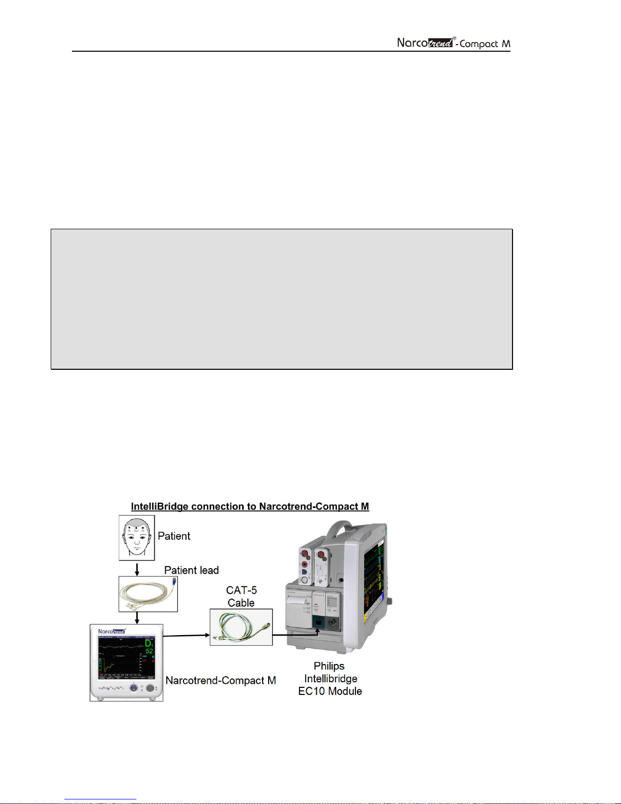
4.2 Device setup (IntelliBridge (optional))
When setting up the device, please proceed as described below:
• Plug the Philips-IntelliBridge EC10 module in a free slot space of the PhilipsIntelliVue patient monitor.
• Connect the Narcotrend-Compact M to the connecting cable (CAT-5 cable) and the
Philips IntelliBridge EC10 module.
• Place the electrodes on the patient's head.
• Connect the patient lead to the Narcotrend-Compact M.
Once the Narcotrend-Compact M is connected to the Philips-IntelliVue patient monitor,
the data transfer begins including the EEG and the results of the automatic
classification.
Page 13
Page 13
4.3 Applying the electrodes
As a standard procedure, the registration of the EEG is carried out with self-adhesive
disposable electrodes, which are placed on the forehead. They are known for their
simplified handling and long-lasting, firm fit. Use the following electrode:
Narcotrend Electrode EE-0203
• The Narcotrend Electrodes are disposable and should not be re-used.
The electrodes are unsuitable if they are re-used.
• Avoid kinking and vigorous pulling of the patient lead because both can
result in cable defects.
• Always follow the instructions of the electrode manufacturer as well.
• Electrodes made of different materials must not be used together.
• Avoid placing the electrodes over bone gaps, scars or skin lesions.
• Whenever electrodes are placed on oedematous skin areas, it is
important to note that the amplitudes can be lower here than over nonoedematous areas.
• Make sure that there are no moisture bridges between the electrodes.
• Lay the patient lead so that it moves as little as possible during the
recording. Furthermore, the patient should not be lying on the
electrodes or on the patient lead since this can result in malfunctions
during the recording.
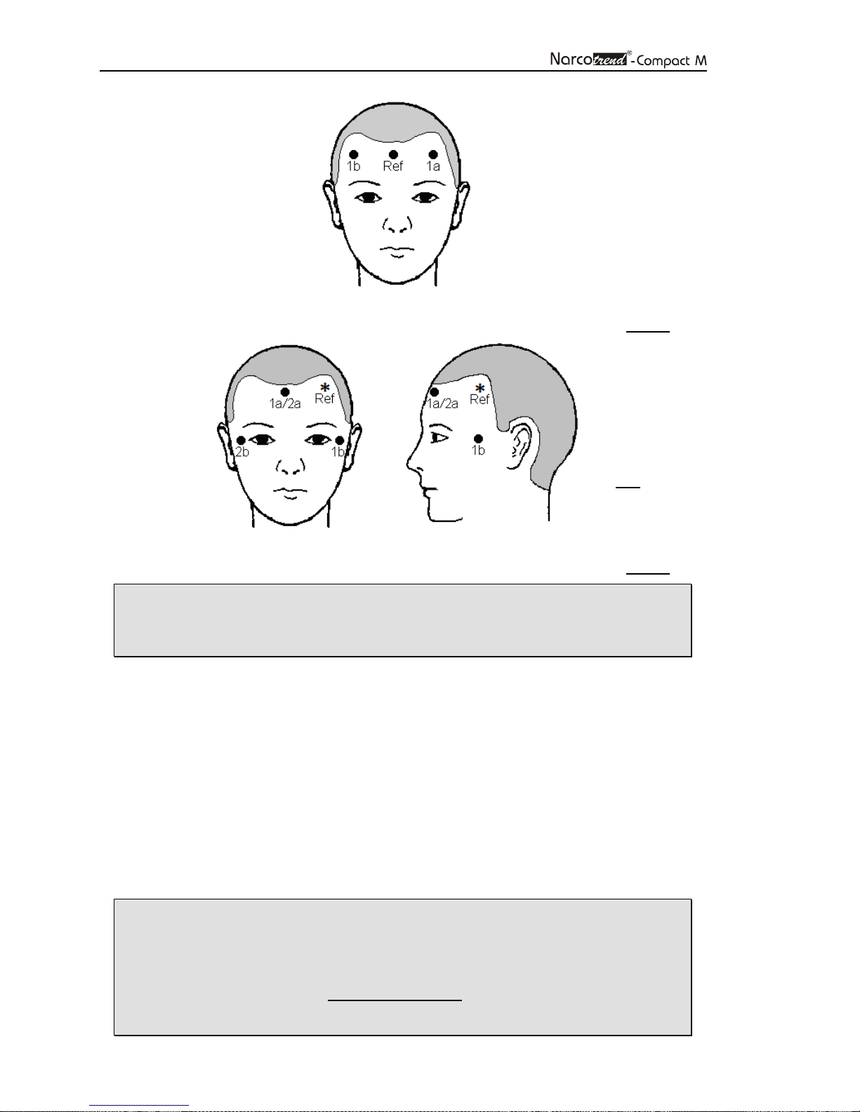
The electrodes should be placed on the hairless skin area of the scalp. They should be
positioned close to the hairline. In the region close to the eyes artifacts may occur,
especially in stages of light hypnosis.
Page 14
Page 14
Ref
(R)
Fig. 4: Electrode positions for disposable electrodes, 1-channel (PKM1)
* The
can be placed anywhere in the
forehead area.
Fig. 5: Electrode positions for disposable electrodes, 2-channel (PKM4)
• Channel 1 (1a1b) is generally positioned on the healthy side;
the evaluation always refers to channel 1.
Channel 2 (2a2b) is positioned on the side to be operated, or sick side.
1. Wipe the skin at the electrode positions with alcohol or an alcohol pad.
2. Apply a drop of preparation cream (0.5 – 1 ml) to a gauze swab. Use the swab
to treat the skin at the electrode positions carefully and thoroughly.
3. Rub the skin dry with a dry gauze swab.
4. Pull off the protective material from the electrode and then stick the electrode on
the skin. Avoid exerting pressure on the center of the electrode since this could
cause the electrode gel to be pressed under the adhesive ring, thus reduces the
electrode adhesion.
5. Connect the pushbutton adapters of the patient lead to the electrodes.
6. Seal the pouch with unused electrodes as airtight as possible.
erence electrode
• Spacing: at least 8 cm (3 in) between
1a and 1b (1-channel recording)
1a/2a and 1b, 1a/2a and 2b (2-channel recording)
• Electrode impedances: < 2 kΩ (max. 8 kΩ)
Ensure uniform impedance values to the extent possible.
Page 15
Page 15
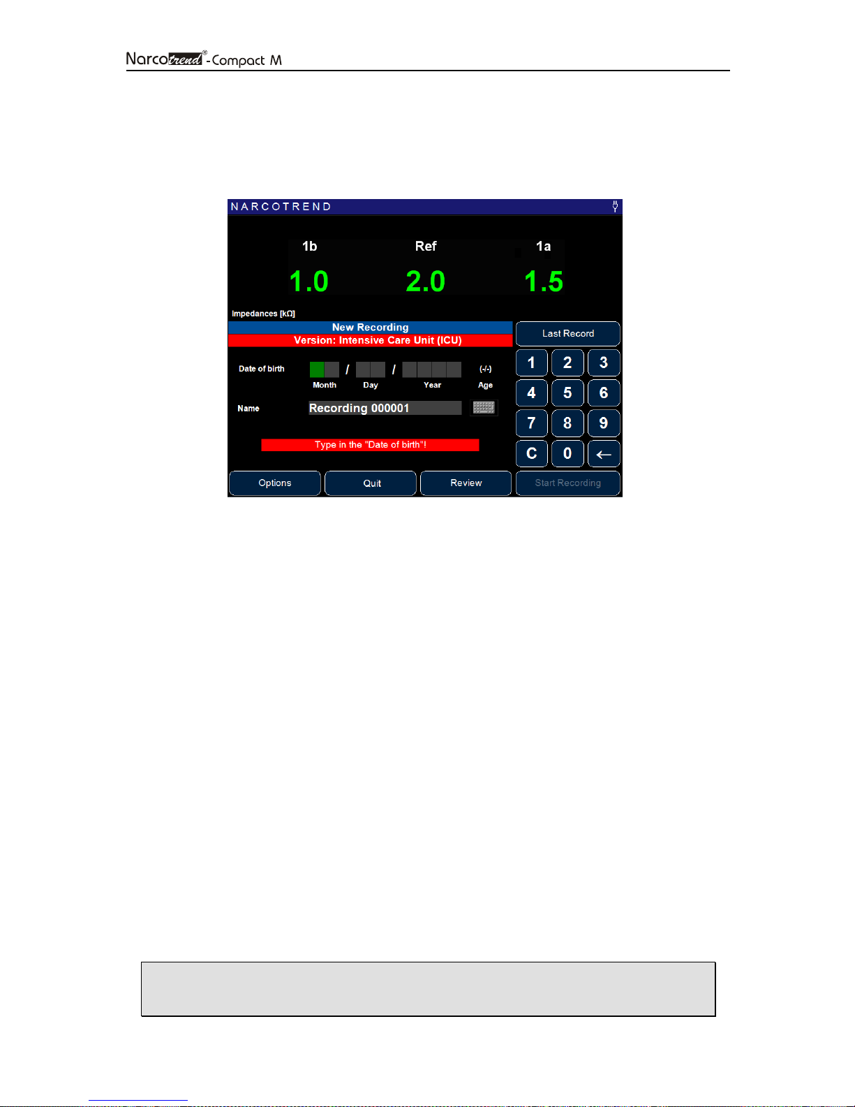
4.4 Start recording / Start screen
After the Narcotrend-Compact M has been switched on, the dialogue for starting a new
recording is displayed:
Fig. 6: Start screen
If the electrodes are already applied and the patient lead is connected, the impedances
are displayed in the upper area of the screen.
The date of birth is entered by using the numeric keypad, as in the figure above.
You can also assign a name for the recording (e.g. patient name). Press the keyboard
symbol on the right-hand side next to the input line for Name. The input operation is
carried out via the displayed screen keyboard.
The button
LAST RECORD
accepts the date of birth and the name of the last record in the
corresponding input lines.
To start a recording the following requirements must be fulfilled
• patient lead is connected
• a valid date of birth has been entered
• the input line “Name” is not empty
• the internal battery is not empty
• there is enough free space on the memory card
Not fulfilled conditions are displayed below the input fields.
If all conditions are fulfilled, start the recording via the button S
TART RECORDING
. The
“Recording screen” appears and from now on the data will be stored.
It is not possible to make a 1-channel-recording with a 2-channel-lead.
The button R
The button Q
EVIEW
is used to show stored recordings (chapter 7).
UIT
is used to switch off the device.
• The touchscreen reacts very sensitively. Please don’t use sharp or
pointed objects like pens or pencils for operation.
Page 16

Page 16
4.5 Options / Start screen
On the Start screen, you can use the O
PTIONS
button to make global program settings.
This includes:
Electrode Settings
Select electrode type: Standard or (Needle (currently not available))
Electrode Check Interval: The time interval between the automatic impedance
measurements can be changed.
Max. Impedance: Shows the set warning / limit value of the permissible
impedance of an electrode.
Max. Impedance Difference: Shows the set warning / limit value of the permissible
impedance difference of the electrodes.
See also chapter 5.9, Electrode Check.
Date / Time
To change the time or date, change the corresponding values and confirm with the
A
PPLY
button.
Language
The language used for the device can be set by selecting the corresponding button.
Marker
Up to 20 different marker texts can be defined in order to access markers with the
predefined texts during the measurement.
Configuration
• User Preferences:
o If the option "Show query for channel 1" is activated, the position of the
electrodes of channel 1 (left side of the head / right side of the head /
alternative position) is requested before the start of the measurement.
A corresponding marker is set at the beginning of the measurement.
• Service: Setup and maintenance menu for service technicians.
• Device Information: Displays device and version information.
Page 17
Page 17
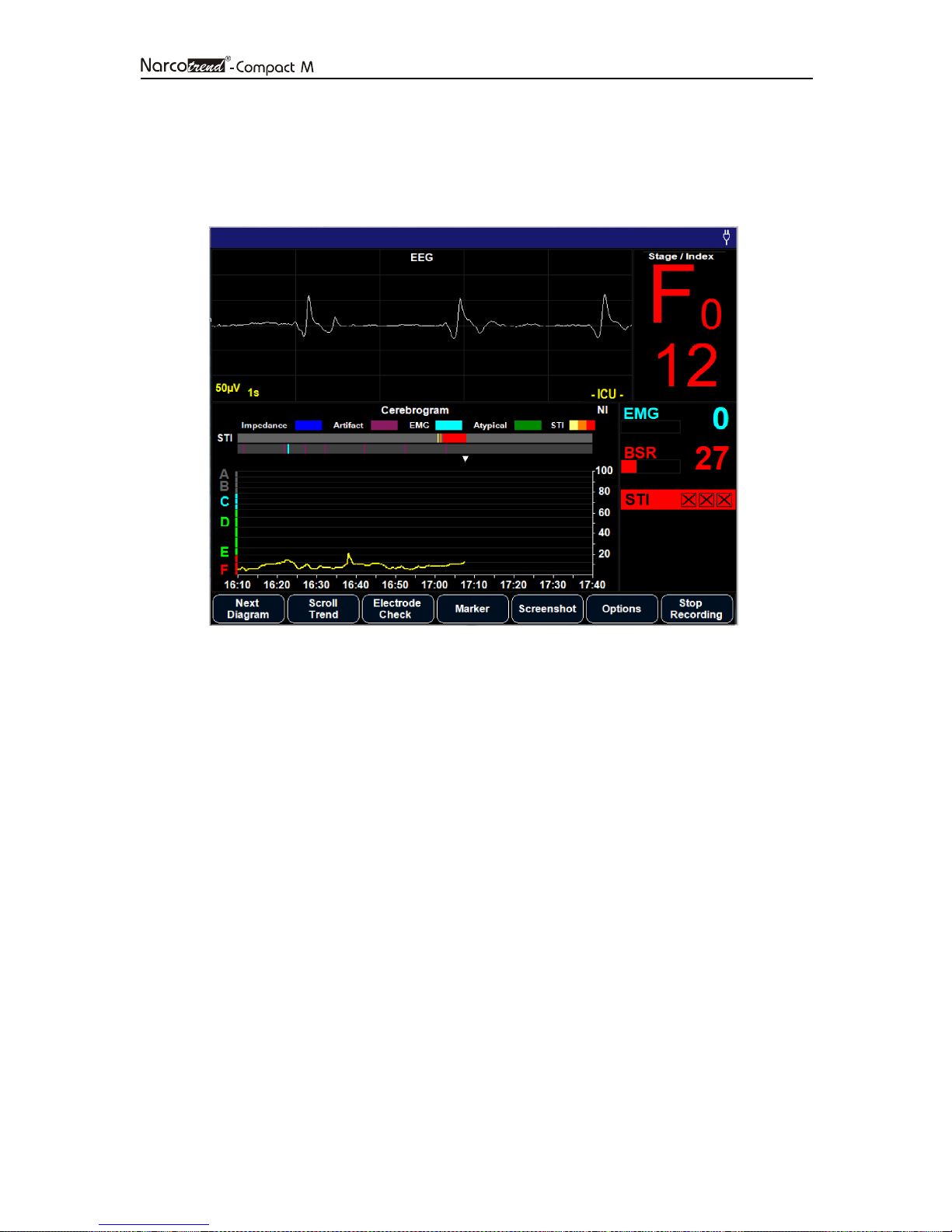
5 Recording screen
In the recording screen, all information about the recording are displayed. Using the
button bar at the bottom margin of the screen, the program is controlled in the recording
mode.
Fig. 7: Recording screen
5.1 Title line
The title line indicates the following information (from left to right):
• Name
• Date of birth and age in years/months
• Date and time
• Bluetooth / RS232-symbol (when function is switched on)
• Power supply symbol or battery symbol
In the title bar also system messages, such as information about the battery capacity
are displayed.
5.2 EEG
The EEG data currently coming from the patient are indicated in the raw EEG window.
In the case of a 2-channel recording, the top curve indicates Channel 1, and the bottom
curve indicates Channel 2.
Within the EEG window, information about artifacts and status messages are also
displayed.
Page 18
Page 18
5.3 Stage / Index
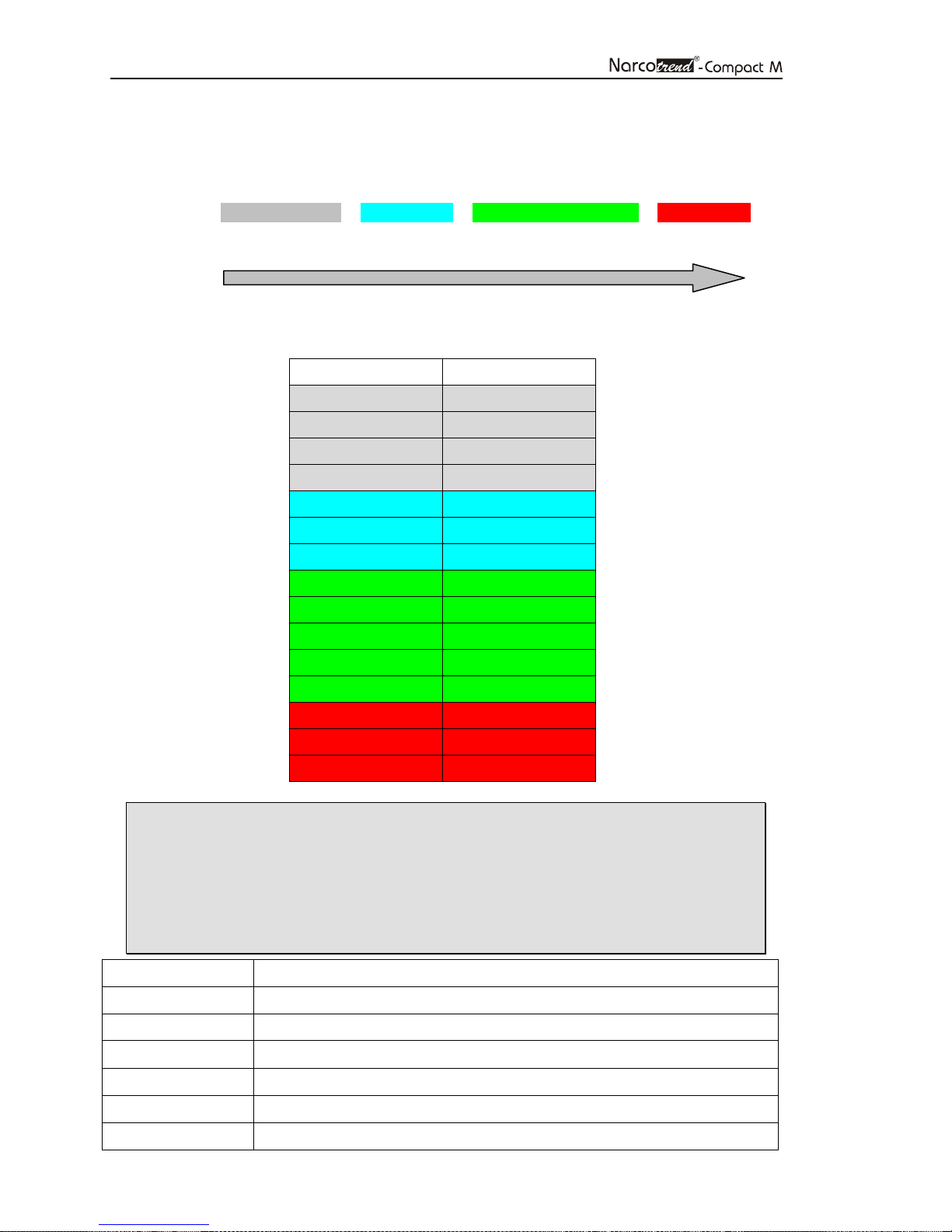
The current automatically classified EEG stage and the EEG index are indicated in the
right top part of the recording screen:
Stage: A – B0 – B1 – B2 – C0 – C1 – C2 – D0 – D1 – D2 – E0 – E1 – E2 – F0 – F1
Index: 100 0
Conscious Deepest hypnosis
Every stage from A to F1 refers explicitly to a range of indices.
Stage Index
A 95 - 100
B0 90 - 94
B1 85 - 89
B2 80 - 84
C0 75 - 79
C1 70 - 74
C2 65 - 69
D0 57 - 64
D1 47 - 56
D2 37 - 46
E0 27 - 36
E1 20 - 26
E2 13 - 19
F0 5 - 12
F1 0 - 4
• A/B classification: In the ICU version not provided
• The current assessment always refers to Channel 1.
• If the raw EEG is not classified, additional information, e.g. recognized
artifacts or atypical signal patterns were displayed. The information is
recorded in the course of time over the cerebrogram
(See the following overview).
Information Description
Start Recording was started successfully, evaluation is running
Impedance At least one impedance limit has been exceeded
Artifact The EEG signal is loaded with artifact interference
Atypical Atypical signal patterns
Sharp waves Occurrence of epilepsy-typical potentials
EMG EMG superposition of the EEG signal
Page 19
Page 19
5.4 Additional parameters
These parameters are displayed on the right side of the recording screen.
5.4.1 EMG
EMG = electromyogram
The EMG index is a measure for the intensity of the electrical muscle activity. The index
is displayed on a scale from 0 (no muscle activity) to 100 (very high amount of muscle
activity).
5.4.2 BSR
BSR = burst suppression ratio
The burst suppression ratio quantifies the suppression percentage of a 60 s EEG
epoch. It is displayed on a scale from 0 (no suppression detected) to 100 (isoelectric
EEG).
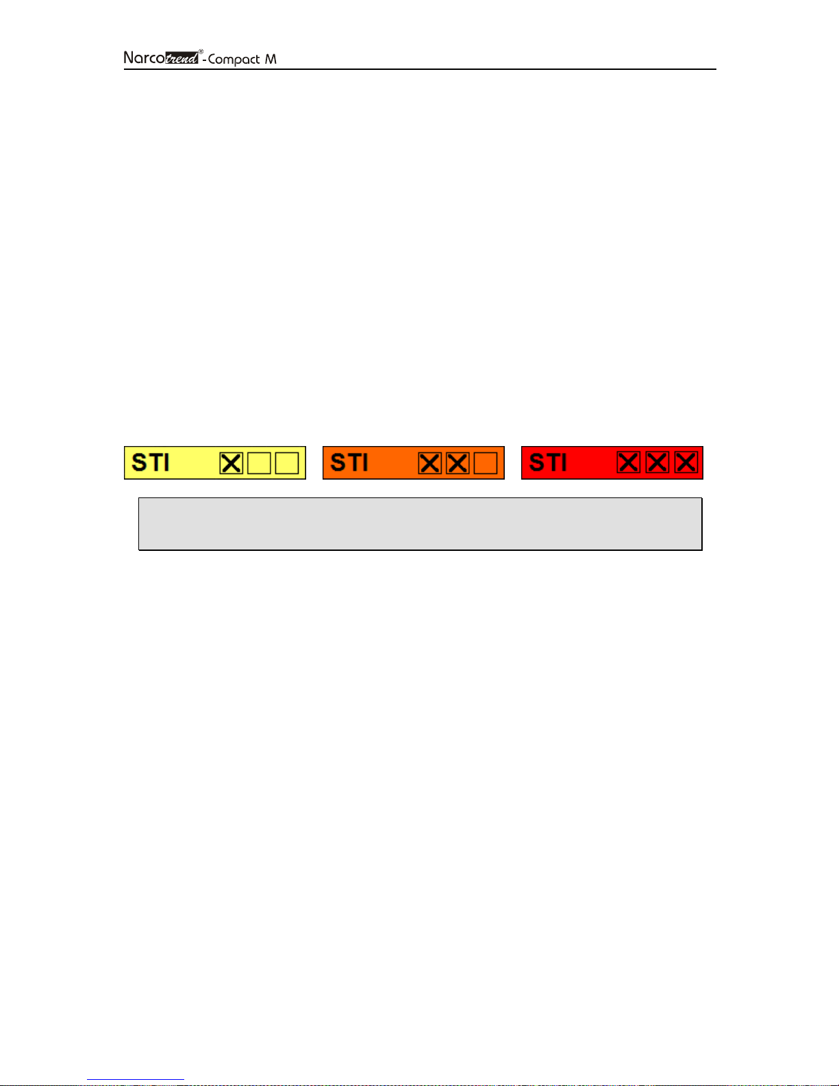
5.4.3 STI
STI = sharp transient intensity
The STI detection shows in three stages the frequency and the intensity of sharply
contoured potentials within the last minute.
Artifacts may be involved in rare cases with the sharply contoured
potentials detected (e.g. cautery).
5.5 Diagrams
The diagrams being offered are displayed in this window. The diagram changing
operation is carried out via the button N
EXT DIAGRAM
.
Page 20
Page 20
5.5.1 Cerebrogram
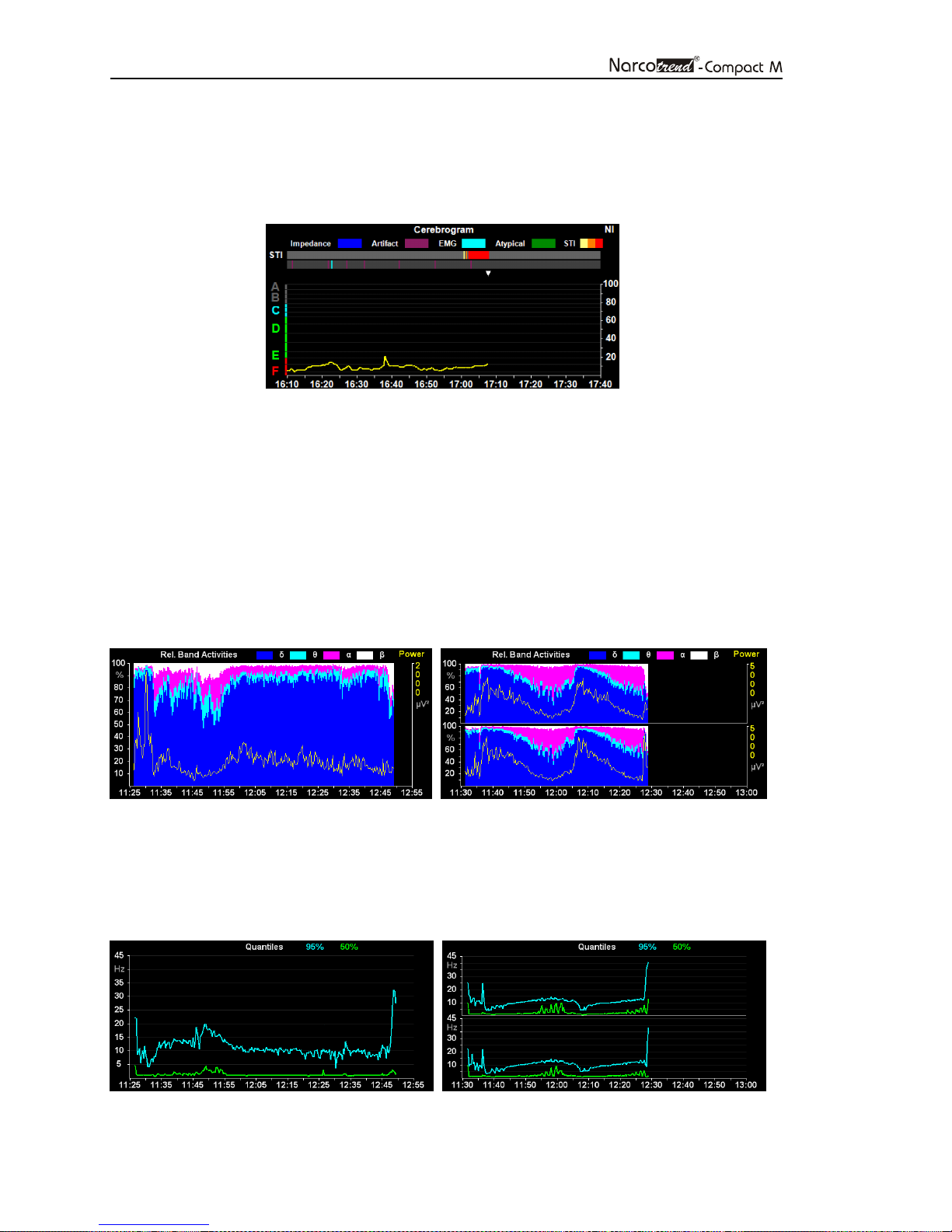
The cerebrogram shows the results of the automatic assessments of the EEG in the
course of time. In the 2-channel version, only the values from the channel 1 are
displayed.
Fig. 8: Cerebrogram
In the gray gradient bar above the cerebrogram, the STI gradient (top) and the detected
artifacts (bottom) are recorded.
The left axis shows the stages A - F with the corresponding sub-stages and the right
axis shows the index range 0 to 100.
In an ongoing recording, a white triangle at the upper margin of the cerebrogram
indicates the current time.
5.5.2 Relative Band Activities / Power
The percent activity proportions for the individual frequency bands and the absolute
power are displayed.
Fig. 9: Relative Band Activities / Power, 1-channel and 2-channel
5.5.3 Quantiles
This diagram shows the median (50% quantile) and the spectral edge frequency (95%
quantile).
Fig. 10: Quantiles, 1-channel and 2-channel
Page 21
Page 21
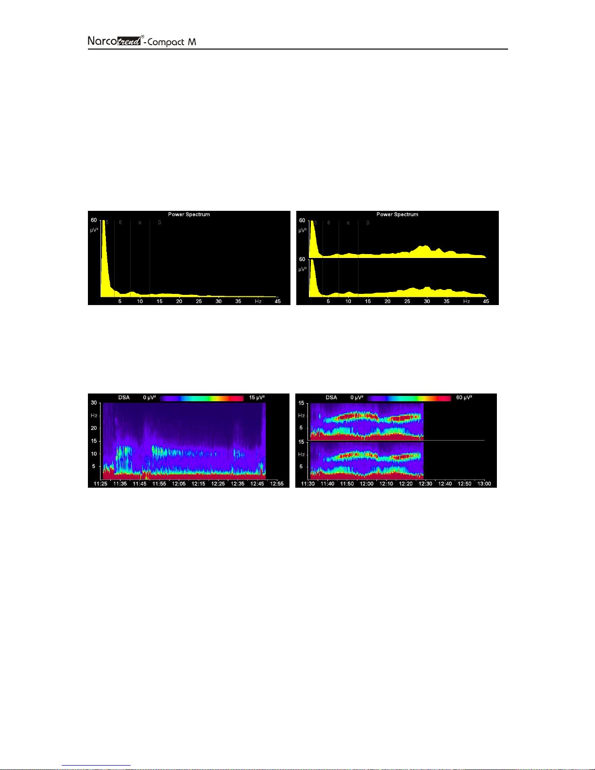
5.5.4 Power Spectrum
The power is displayed in the power spectrum depending on the frequency. The
individual frequency bands are delimited from one another by vertical lines:
δ (delta band) : 0.5 – 3.5 Hz
θ (theta band) : 3.5 – 7.5 Hz
α (alpha band) : 7.5 – 12.5 Hz
β (beta band) : > 12.5 Hz
In the very deep stages E2, F0 and F1, the power spectrum is shown in gray.
Fig. 11: Power Spectrum, 1-channel and 2-channel
5.5.5 DSA
The DSA (Density Spectral Array) is a color-coded representation of the frequency
components of an EEG (violet = low power values, red = high power values).
Fig. 12: DSA, 1-channel and 2-channel
Page 22

Page 22
5.6 EEG analysis for children in the first year of life
The analysability of anesthesia EEGs registered for children in the first months of life,
will depend to a large extent on the children's level of development. Appearing from the
age of approximately three months until the age of 12 months in an increasing number
of children, are typical EEG anesthesia stages, which can be classified visually and
automatically.
EEG classification among children under the age of 60 days
For this age group only EEG classifications for stages with implied or clear suppression
lines (E2 to F1) are displayed. The scale of the cerebrogram is designed accordingly.
If there is an EEG without suppression lines, the output is “Undiff. EEG”. This stands for
“undifferentiated EEG”.
EEG classification among children between the age of 60 days and the age of 1
For children of this age the full A-F scale is displayed on the left side of the cerebrogram
window.
From the outset of measurements the EEG is analysed for certain attributes, which
suggest a mature and thus fully classifiable EEG.
As long as no fully classifiable EEG is detected, instead of an indication of stage or
index, the output “Undiff. EEG” is displayed in the index field, if the raw EEG shows no
sign of suppression lines. If the EEG has been graded as classifiable, from now on
classifications can also be outputted throughout the stages E2 to F1.
Page 23
Page 23
Button
Action
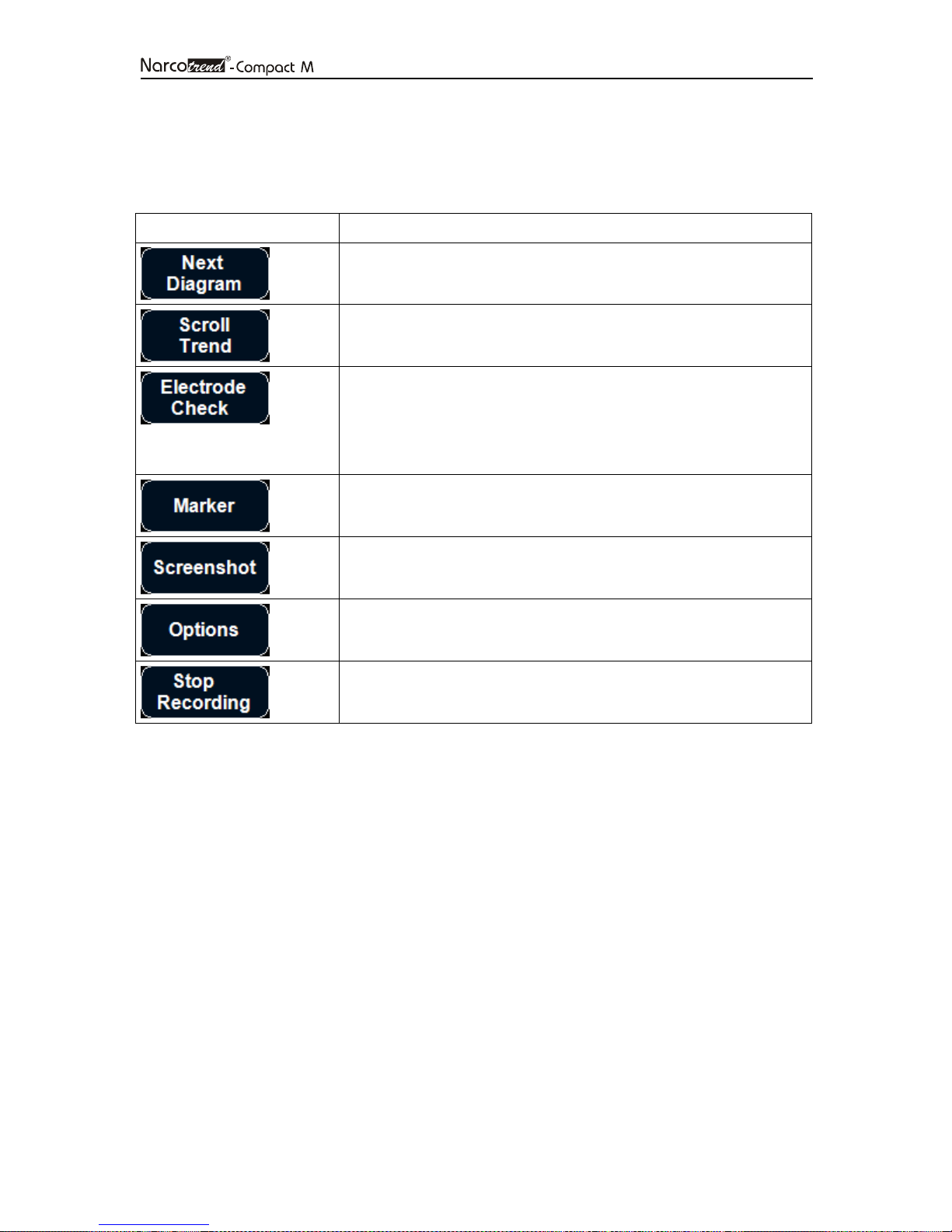
5.7 Button bar
The program is controlled in the recording mode via the button bar on the bottom edge
of the screen:
Changes the content of the diagram window.
Starts the review mode.
Starts the manual electrode check and shows the
impedance values of each electrode. The button text is
changed to “EEG”.
Pressing the button again stops the manual electrode test
and displays the EEG again.
Shows the menu for setting and editing markers (only
available in the extended version).
Generates from the current screen a PNG image file.
Opens a dialogue to change the program options.
Stops the recording of the EEG. The Start screen is
displayed again.
Page 24
Page 24
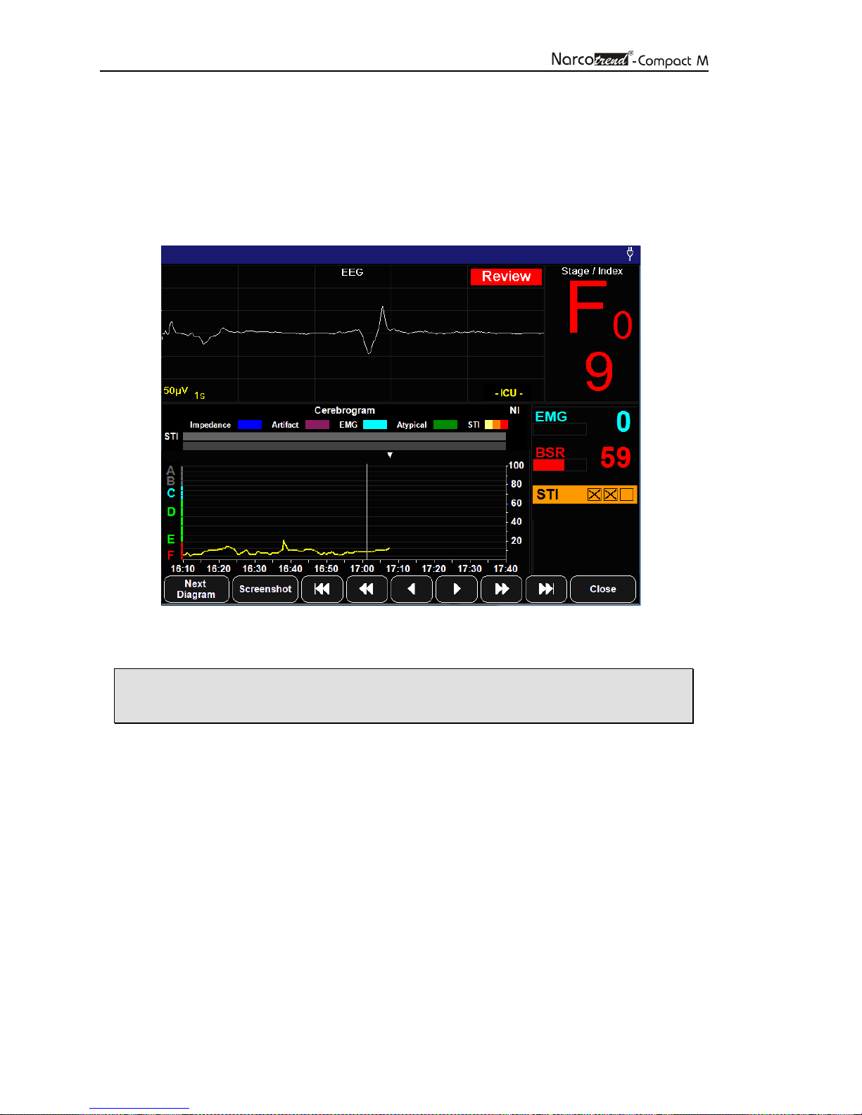
5.8 Review mode
To start the review mode, press the button S
possible to access previous EEG epochs and diagrams of the current recording. This
mode enables the user to scroll back and forward within up to 24 hours of the current
recording. The current EEG is still recorded, analysed and saved while the review mode
is active.
CROLL TREND
. In the review mode it is
Fig. 13: Recording screen during the review mode
• In the review mode, the current EEG and classification is not shown.
This is indicated by the red flashing message „Review“.
A vertical line in the diagrams with a time axis (e.g. Cerebrogram) marks the recording
time of the displayed EEG and the related parameters.
It is possible to choose any point on the time axis by tapping on the touchscreen or to
navigate through the recording via the following buttons.
The markers that are located within a time range of ± 2 minutes of the selected time will
be displayed in a text box.
Page 25
Page 25
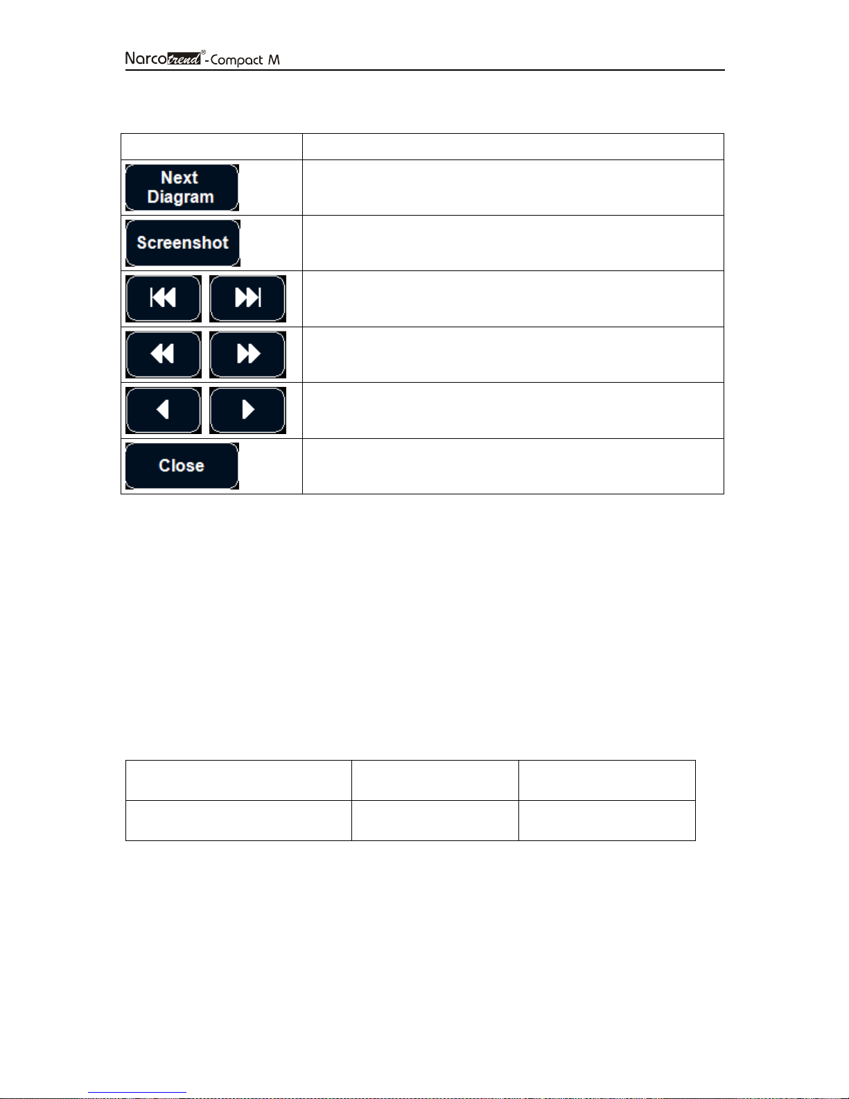
Button
Action
Changes the content of the diagram window.
Generates from the current screen a PNG image file.
Jumps to the start / end of the recording.
1 hour back / ahead.
5 seconds back / ahead.
Ends the review mode and returns to the recording screen to
display the current values.
5.9 Electrode settings
A manual electrode check can be carried out at any time independent of the automatic
electrode checks.
Adherence to the limit values for the impedances is required in order to ensure proper
operation of the device. Furthermore, it is important to make sure that the impedance
values of the individual electrodes are as uniform as possible. Whenever the limit
values for the impedances or the differences between the impedances are exceeded,
analysis of the incoming EEG data is impossible, and a corresponding message is
shown.
Standard limit values:
Impedances Impedance differences
Standard electrodes
< 8 kΩ < 5 kΩ
Page 26
Page 26
Button
Action
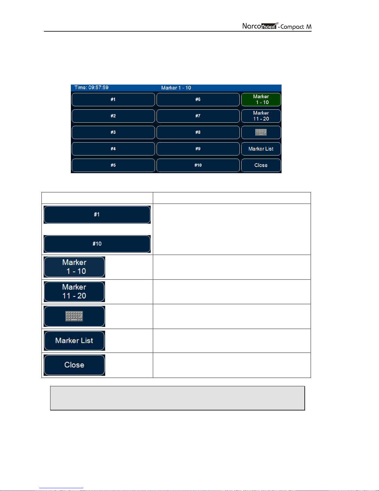
5.10 Marker
The MARKER button displays a menu for setting and editing markers.
Fig. 14: Set and edit markers
Sets markers with predefined text.
...
The text can be changed through the global
program requirements (O
PTIONS
button on the
start screen).
Shows the list of predefined markers 1-10.
Shows the list of predefined markers 11-20.
Sets markers with self-defined text.
Shows the list of all set markers. The text of set
markers can be changed.
Closes the menu and switches back to the
recording screen.
• When a marker has been set, it is indicated by a yellow triangle above
the upper margin of diagrams with a time axis.
Page 27
Page 27
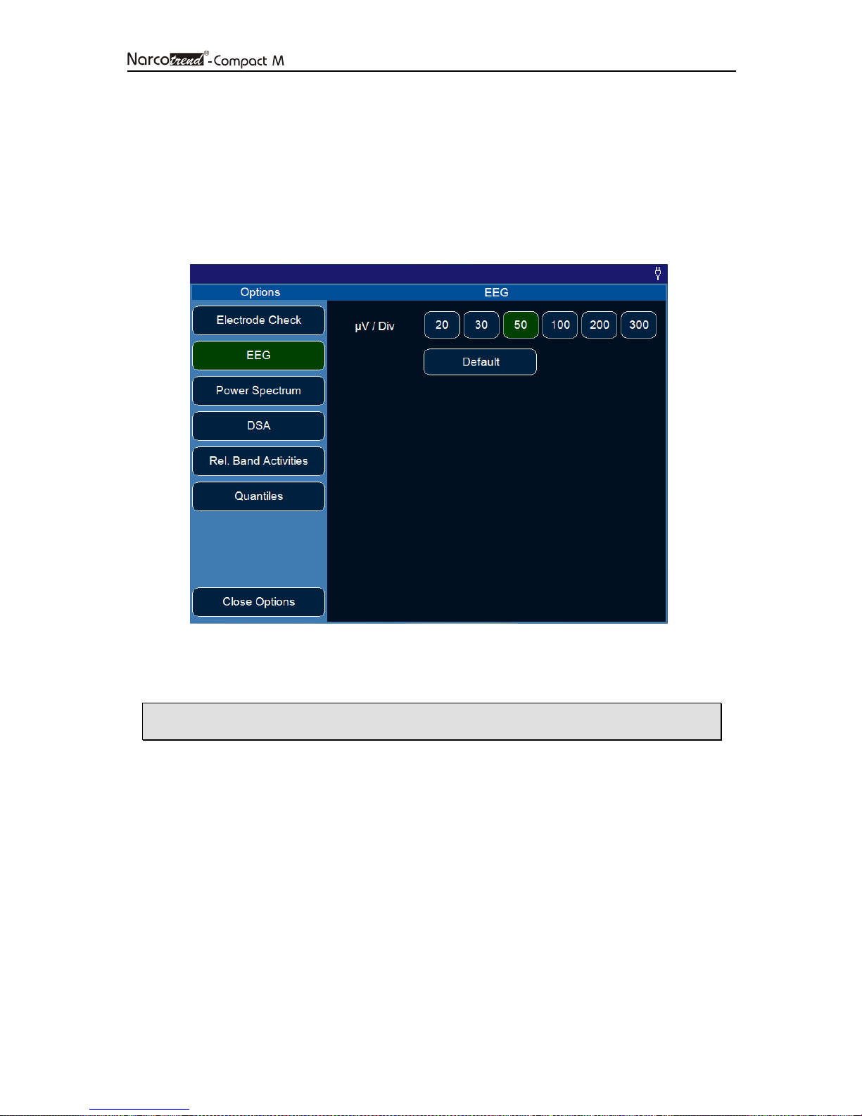
5.11 Options
This dialogue is used to adjust several program options.
The preferences for the automatic electrode check and the diagram scales can be
changed.
Fig. 15: Menu - Options
• The settings in this dialogue are valid only for the current recording.
Page 28
Page 28
Narcotrend
-
Index
Stage
Comment
100
- 95 A awake
94 - 90 B0
89 - 85 B1
84 - 80 B2
79 - 75 C0
74 - 70 C1
69 - 65 C2
64 - 57 D0
56 - 47 D1
46 - 37 D2
36 - 27 E0
26 - 20 E1
19 - 13 E2
12 - 5 F0
6 EEG and evaluations (RS232 / IntelliBridge
connector)
The Narcotrend-Compact M provides the following values and evaluations via the
RS232 / IntelliBridge connector.
6.1 EEG
Depending on the connected patient lead, the one-channel or two-channel EEG is
transmitted (EEG or EEG1/EEG2).
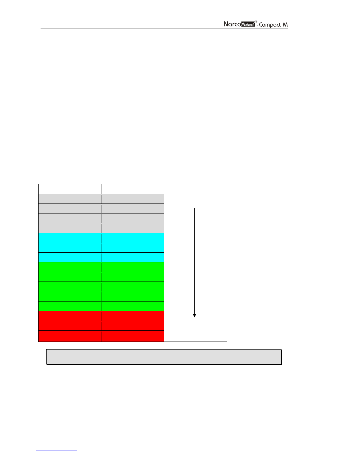
6.2 Narcotrend-Index NI
Result of the automatic classification.
Only for IntelliBridge:
On the Philips-IntelliVue patient monitor only the Narcotrend-Index can be represented,
the stage is not visible.
The following table shows the relationship between Narcotrend-Index and stage.
4 - 0 F1
• The Narcotrend-Index always refers to Channel 1.
deep hypnosis
Page 29

Page 29
Label
Label
6.3 Additional parameters
There are additional parameters like the EMG index, the BSR and the STI available,
see table below.
Only for IntelliBridge:
To view the additional parameters in the IntelliBridge device data window, either
• select the setup key on the EC10-module, or
• select the External Devices SmartKey and then select the pop-up key with the
device name on it, or
• direct tap on the EEG curve and select in the appearing window “External
Devices”, then tap on „Show Device Data“.
*L/LT = Channel 1 (left)
*R/RT = Channel 2 (right)
Parameter
EMG index EMG EMG EMG index (EMG = electromyogram) is a measure of the
BSR BSR LT BSR
STI* STI STI
Delta % DL LT %DL
Theta % TH LT %TH
Alpha % AL LT %AL
Beta % BE LT %BE
1-Channel
2-Channel
RT BSR
RT %DL
RT %TH
RT %AL
RT %BE
Description
intensity of the electrical muscular activity. The EMG
index is shown on a scale of 0 (no muscle activity) to 100
(very strong muscle activity).
The BSR (burst suppression ratio) is the percentage of
suppression lines in the EEG. The value refers to the last
60 s and is issued as a value between 0 (no suppression
lines) and 100 (continuous suppression line).
STI = Sharp Transient Intensity
The STI detection shows on a scale of 0 to 100 the
frequency and the intensity of sharp potentials within the
last minute.
Rel. spectrum power Delta: 0.5 – 3.5 Hz
Rel. spectrum power Theta: 3.5 – 7.5 Hz
Rel. spectrum power Alpha: 7.5 – 12.5 Hz
Rel. spectrum power Beta: > 12.5 Hz
Power TP LT TP
Median MPF LT MPF
Edge
frequency
Imp. 1a 1a 1a Impedance for electrode 1a [kΩ]
Imp. 1b 1b 1b Impedance for electrode 1b [kΩ]
Imp. Ref Ref Ref Impedance for electrode Ref [kΩ]
Imp. 2a 2a Impedance for electrode 2a [kΩ]
Imp. 2b 2b Impedance for electrode 2b [kΩ]
SEF LT SEF
RT TP
RT MPF
RT SEF
Total output [µV²]
The median corresponds to the 50% quantile of the
power spectrum [Hz]
The spectral edge frequency corresponds to the 95%
quantile of the power spectrum [Hz]
Page 30
Page 30
INOP
Description
6.4 Electrode check
To ensure the proper working of the system, the impedance values may not exceed a
certain threshold. Furthermore, make sure that the impedance values of the individual
electrodes are as uniform as possible. At too high impedances or impedance
differences no evaluation of the incoming EEG data is possible, and an appropriate
message (NARCOTR CHECK IMP) is outputted.
Impedances Differences of impedances
Threshold values
< 8 kΩ < 5 kΩ
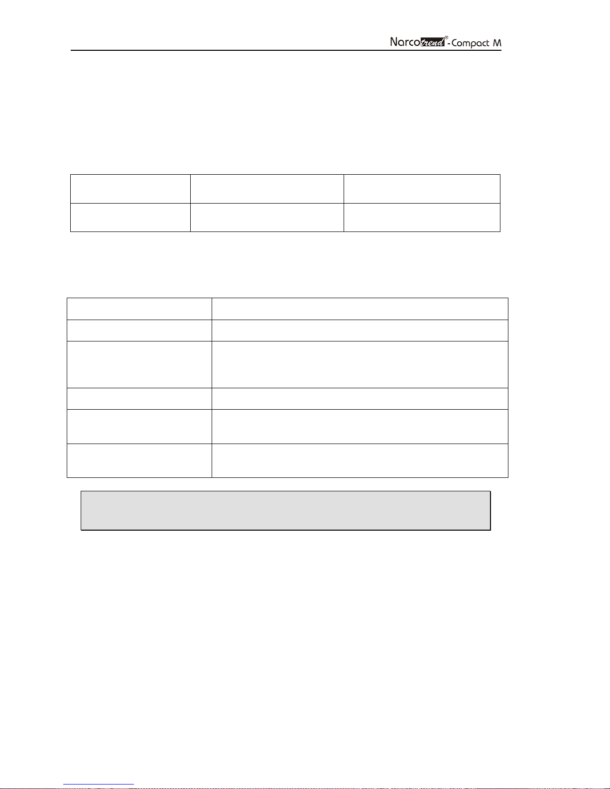
6.5 Error messages
The following error messages are outputted:
NARCOTR LEAD OFF Patient lead is not connected.
NARCOTR CHECK IMP One or more impedance values have exceeded the
maximum limit. Check the position of the electrodes on the
patient's head and the connections at the electrode lead.
NARCOTR 50/60 HZ AC artifacts occur in the signal.
NARCOTR INTERFER Errors may occur in the EEG signal, e.g. by high-frequency
surgery (cautery).
EMG No classification due to high intensity of the electrical
muscle activity.
• In case of excessive load of artifacts the Narcotrend-Index is not
calculated.
Page 31
Page 31
7 Analyse recording
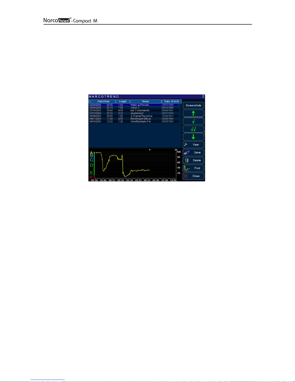
Select the button R
recordings or screenshots that have been stored. A recording or screenshot is selected
by direct touch or via the buttons on the right-hand side next to the list.
Only for recordings:
At the bottom of the screen the Cerebrogram of the selected recording is shown (max.
the first 90 minutes).
EVIEW
in the start screen. The dialogue displays a list of all
Fig. 16: Dialogue „Review“
Page 32
Page 32
Button
Action
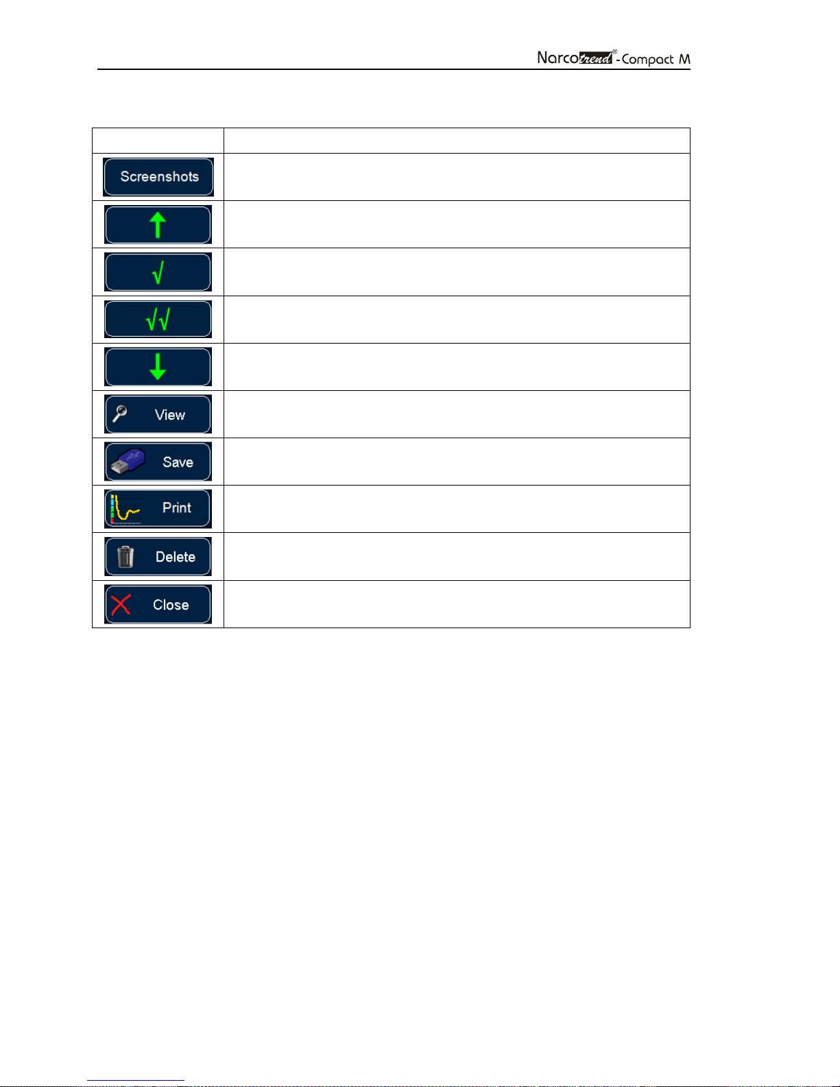
The buttons on the right have the following functions:
Switchover from recordings to screenshots.
Moves the selection bar up.
Marks a selected recording/screenshot and moves the selection bar
down.
Marks all recordings/screenshots.
Moves the selection bar down.
Displays the selected recording/screenshot (review).
Copies the selected recordings/screenshots to an USB flash drive.
Creates a PDF-File on the USB flash drive.
Deletes the selected recordings/screenshots.
Closes the dialogue. Returns to the start screen.
Page 33
Page 33
7.1 View
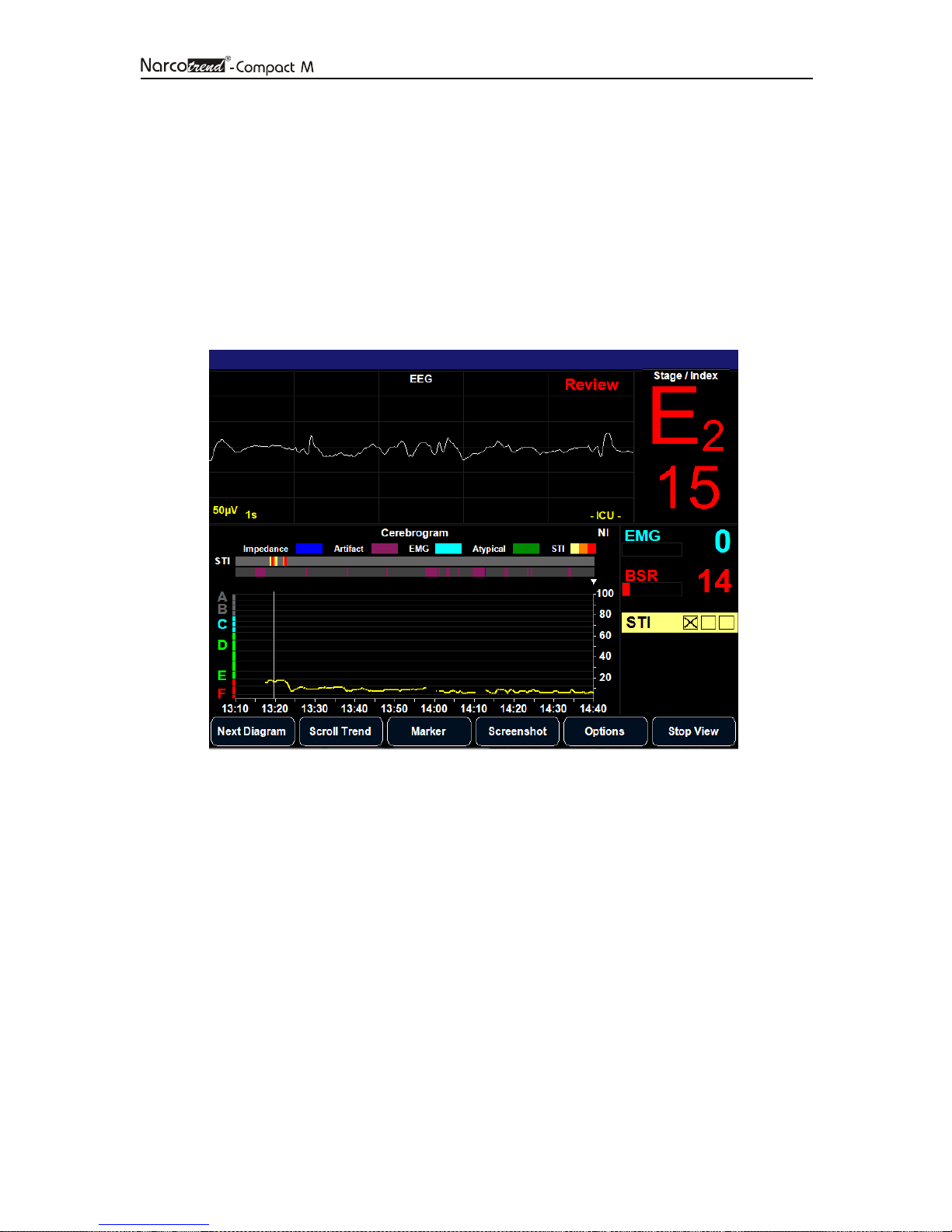
The selected recording or screenshot is read and displayed.
Only for recordings:
If recordings which are longer than 24 hours shall be displayed, at first the recording
period (“day”) has to be selected. This day will then be shown completely.
Apart from the button bar, the screen is identical with the review mode screen of an
ongoing recording.
Fig. 17: Screen “View” (review mode)
Page 34
Page 34
Button
Action
Button
Action
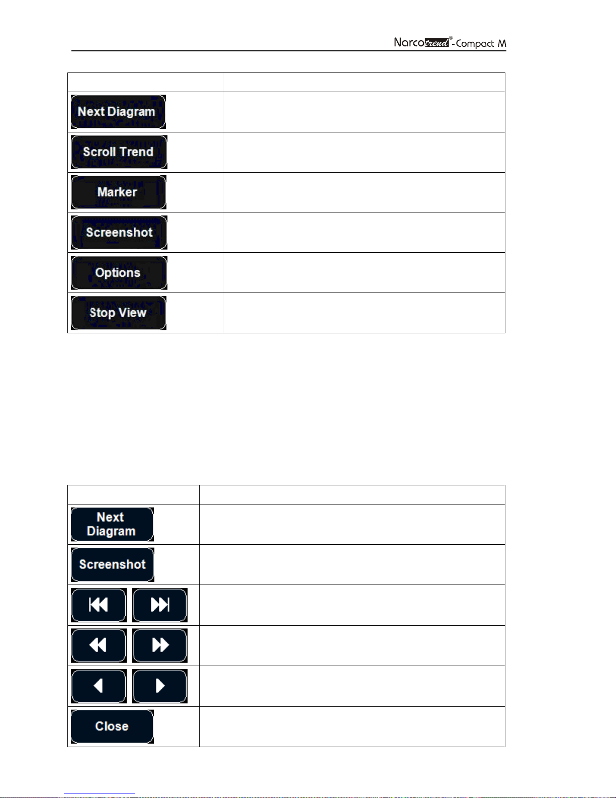
Changes the content of the diagram window.
Shows the button bar to navigate through the recording.
Shows the list of all markers (only available in the
extended version).
Generates from the current screen a PNG image file.
Opens a dialogue to change the diagram scales.
Ends the display of the recording and returns to the
dialogue „Analyse recording“.
A vertical line in the diagrams with a time axis (e.g. Cerebrogram) marks the recording
time of the displayed EEG and the related parameters.
It is possible to select any point on the time axis by tapping on the touchscreen or to
navigate through the recording via the buttons.
Date and time in the title line are identical with the currently marked and displayed
recording time.
Via the button S
CROLL TREND
, it is possible to access a further button bar to navigate
through the recording.
Changes the content of the diagram window.
Generates from the current screen a PNG image file.
Jumps to the start / end of the recording.
1 hour back / ahead.
5 seconds back / ahead.
Ends the review mode and returns to the recording screen to
display the current values.
Page 35
Page 35
7.2 Save
The selected or all marked recordings or screenshots are saved on a USB flash drive.
• This is possible when the USB storage medium has been recognized
and accepted by the device.
• The connected USB storage medium has to be FAT32.
• Due to the great variety of existing USB storage media, we cannot
guarantee that each USB storage medium will be accepted by the
device.
• Depending on the memory capacity, the detection of a USB storage
medium may take some minutes.
• The USB port provides 500mA at 5V.
7.3 Print
For the selected or for all marked recordings, PDF files consisting of the cerebrograms
are created on the connected USB flash drive. Each PDF file contains the whole course
of a recording.
• Please read the notes concerning USB storage media in section 7.2
7.4 Delete
Delete the selected or all marked recordings or screenshots definitely from the device.
Page 36

Page 36
8 Cleaning, maintenance, repair
8.1 Care and cleaning
To clean the Narcotrend-Compact M and the display surface use a lint-free cloth
moistened with warm water (max. 40 °C / 104 °F) and soap, a thinned non-corrosive
cleaner, or an ammonia/alcohol-based cleaner.
To disinfect the Narcotrend-Compact M and the display surface use a lint-free cloth
dampened with a 10% bleach / 90% water solution (household bleach [containing less
than 10% sodium hypochlorite]) or wipe the surfaces with disinfectant containing alcohol
(e.g. Meliseptol®) or disinfectant with the active ingredient chlorine dioxide
(e.g. Tristel Jet®).
After cleaning / disinfection, dry all areas with a lint-free absorbent paper towel.
Sterilization is not carried out.
The cleaning / disinfection of the accessories, e.g. patient leads, are carried out in the
same way described above.
• Use cleaning and disinfecting agents always in observance to the
manufacturer's instructions.
• Do not allow any water to enter the housing.
• Do not use abrasive detergents.
• Do not mix disinfectants (such as bleach and ammonia), dangerous
gases can occur.
Page 37
Page 37
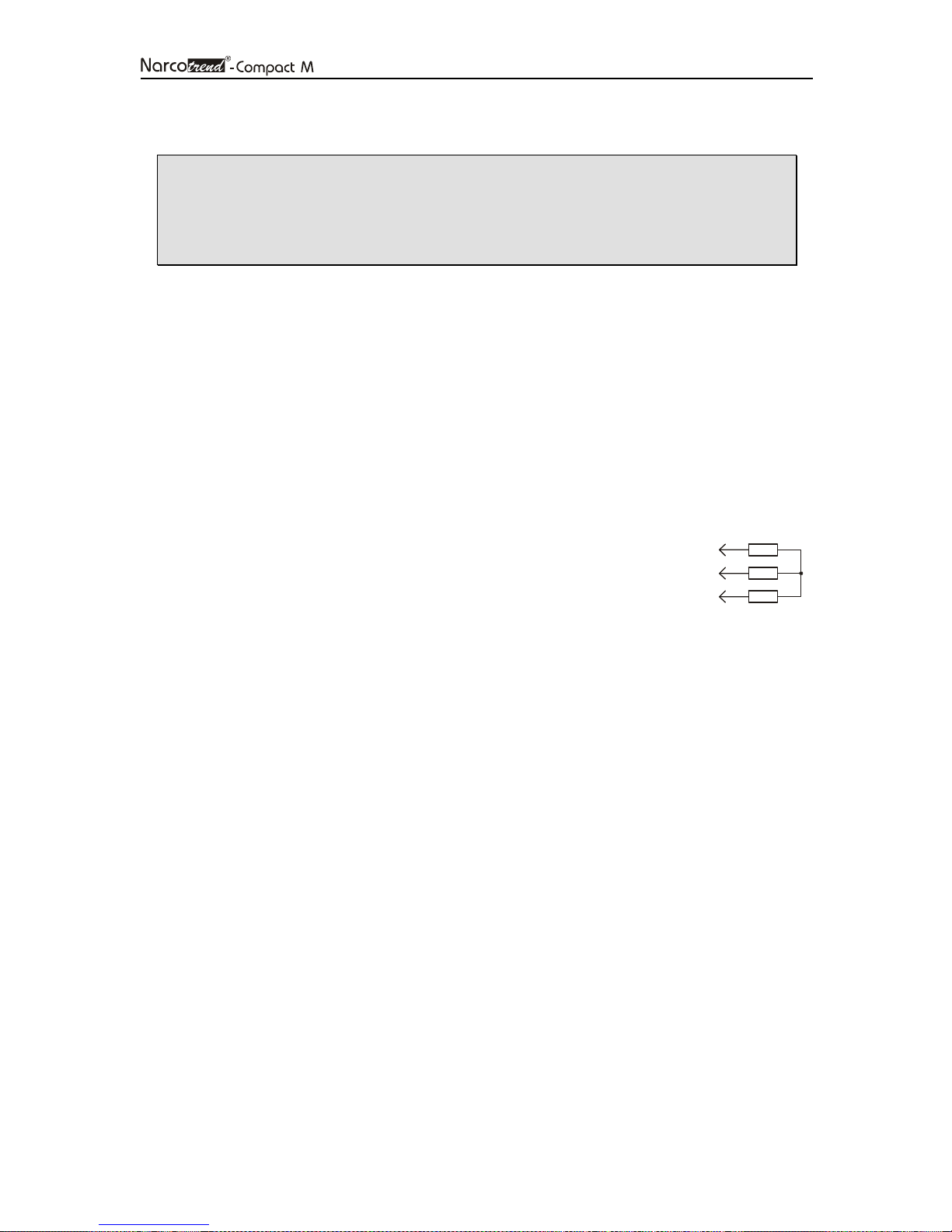
1 k
1 k
1 k
8.2 Recommended checks
• The recommended checks must only be carried out by a qualified
service technician.
• Before and during each application, observe the safety instructions
included in Chapter 3.
Inspections related to safety and measuring technology are not required. However, it is
advisable to carry out the following tests every 12 months.
Visual inspection
• Presence of all system components
• Signs of damage on the Narcotrend-Compact M (cracks, missing housing parts)
• Condition of the plug-in connections on the Narcotrend-Compact M (firmly
seated in the housing, pins not bent)
• Condition of the patient lead (sheath, plug-in connections undamaged)
• Proper labeling (type plates fitted, legible)
Electrical measurements
• Patient leakage current (application part: electrode pushbutton adapter)
Functional test (if test adapter is available)
• Starting an EEG recording incl. impedance measurement after
plugging a test adapter into the pushbutton adapter.
• A simulated zero line must be output. The impedance
values must amount to approx. 1 kΩ.
Documentation
• Preparing a test report including identification of the inspector, the measuring
method and the test results.
Ω
Ω
Ω
Page 38

Page 38
Error messages
Description
Battery is low. Connect power
8.3 Error messages
No patient lead is connected Patient lead is not connected to the monitor. To start a
new measurement a patient lead must be connected.
Impedance too high! Adjust
electrodes
Impedance difference too
high
Check Electrodes! One or more electrodes have no measurable contact with
Electrodes offline: (1a…2b)
„off“
“?”
Shown in screen “electrode
check”
Connect 1-channel patient
lead
Type in the “Date of birth“! To start a measurement you must enter a date of birth.
The measured impedance value of one or more
electrodes exceeds the maximum limit. Check the position
of the electrodes on the patient's head and the
connections to the patient cable. Press the pad gently or
glue on a new electrode.
The difference between two measured impedance values
exceeds the maximum limit. Check the position of the
electrodes on the patient's head and the connections to
the patient cable. Press the pad gently or glue on a new
electrode.
the skin. Check the position of the electrodes on the
patient's head and the connections to the patient cable.
Press the pad gently or glue on a new electrode.
Check the placement/fit of the electrodes whose
impedance levels are not displayed as green.
Without the additional option 2-channel, 2-channel
measurement cannot be started. Connect a 1-channel
patient lead and then start a new measurement.
Check “Date of birth“! The entered date of birth is incorrect or is in the future.
Check the date of birth.
Type in the “Name“! To start a measurement you must enter a name. The
name of the measurement can also be "measurement
000001". You can also enter the patient's ID.
The monitor is operated on battery power and the battery
supply!
Battery is empty. Connect
power supply!
Battery is empty. Recording
is terminated!
is nearly empty. Connect the Narcotrend-Compact M power supply to continue working.
The monitor is operated on battery power and the battery
is empty. Connect the Narcotrend-Compact M - power
supply immediately to prevent that current measurement
is automatically stopped before the power goes off.
The unit is operated on battery power and the battery is
empty. To prevent data loss, the current measurement
has been completed. Connect that Narcotrend-Compact
M - power supply to prevent the device switches off.
Page 39

Page 39
Error messages
Description
Not enough free disk space.
Recording terminated!
The current measurement was stopped because there is
not enough space available to store the data. Push the
button R
EVIEW
to save or delete some of the past
measurements and get free space on the hard disk.
EEG storage left: < 100 hours The available capacity is less than 100 hours. It is
possible to start measurements but it is recommended to
delete measurements in the “Review mode”. If necessary
you can save the measurements beforehand.
Impedance Due to high impedance values or impedance differences,
a classification is impossible. Check the position of the
electrodes on the patient's head and the connections to
the patient cable. Press the pad gently or glue on a new
electrode.
50 Hz or 60 Hz AC artifacts occur. In case of excessive artifact load, the
signal is not evaluated. If the error persists please contact
support (see contact on the back of the cover page).
EMG Due to excessive EMG artifacts, a classification is
impossible. (EMG = electromyogram, intensity of electrical
muscle activity)
Undiff. EEG This message will only be displayed with the occurrence
of an undifferentiated EEG in the case where measuring
takes place in children aged 12 months or less. Such an
undifferentiated EEG cannot be classified apart from E2F1. In the case of the occurrence of a differentiated EEG,
this message will not be displayed, but instead classified
even in the case of children aged 12 months or less.
Also see Chapter 5.6 in connection with this.
Page 40
Page 40
8.4 Battery
The internal battery is a consumable that loses its capacity after longer use. If the mains
buffering time is no longer achieved the battery should be replaced.
8.4.1 Checking the battery
Connect the Narcotrend-Compact M to the mains for at least 2 hours. Interrupt the
power supply and switch the equipment on. If the Narcotrend-Compact M can no longer
be operated for 2 hours in battery mode the battery may be replaced.
8.4.2 Changing the battery
• The internal battery must only be replaced by a qualified service
technician.
• Do not change the battery while the Narcotrend-Compact M is in use
with a patient.
• Use only original parts. See "Spare parts and part numbers."
The following steps are to be carried out:
1. Unplug the power supply from the Narcotrend-Compact M.
2. Open the battery box by loosening the 2 screws at the back side.
3. Remove the battery by disconnecting the battery cable.
4. Plug in the battery cable of the new battery and place the battery in the battery
box.
5. Replace the battery box cover and fix the 2 screws again.
6. Reconnect the power supply and test the device.
8.5 Disposal
• Do not dispose of the device with unsorted household waste.
• The Narcotrend Electrodes are disposable and should not be re-used.
The electrodes are unsuitable if they are re-used.
The Narcotrend-Compact M (especially the battery) and the patient lead must be
disposed by a disposal company for electronic wastes.
Disposable parts must be discarded according to hospital rules and in an
environmentally safe way.
Page 41
Page 41
9 Technical data
9.1 Symbols
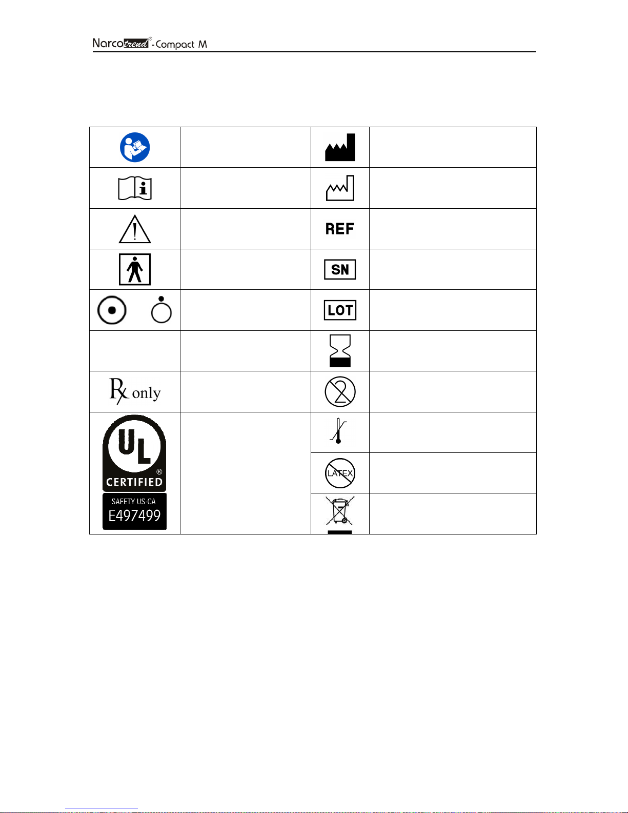
/
IPX1
Follow instructions for use
Consult the instructions for
use
Attention
Type BF applied part
Indicates ON / OFF for a
part of equipment
IP-Code (Protection
against dripping water
(vertically falling drops))
Federal law (U.S.A.)
restricts this device to sale
by or on the order of a
MEDICAL — GENERAL
MEDICAL EQUIPMENT
AS TO ELECTRICAL
SHOCK,
FIRE AND MECHANICAL
HAZARDS ONLY IN
ACCORDANCE WITH
ANSI/AAMI ES60601-1
(2005) + AMD 1 (2012)
Manufacturer
Date of manufacture
Order number
Serial number
Lot number
Expiration date
For single use only
Temperature limit (from...to)
Latex-free
Do not dispose of the device with
unsorted household waste
The last two digits of the serial number indicate the year of production
(e.g. 18 = 2018, 19 = 2019).
Page 42

Page 42
0482
9.2 Classification and technical data
Classification
Product Narcotrend
Type/Model Narcotrend-Compact M
Manufacture MT MonitorTechnik GmbH & Co. KG
Maienbass 27
24576 Bad Bramstedt, Germany
Intended use EEG - measurement and analysis with output
a parameter for anesthesia and
sedation control
Classification according
to Annex IX of Directive 93/42/EWC IIb
concerning Medical Devices
UMDNS EEG-Monitor 12-602
Class Medical equipment of protection class II
Electromagnetic Compatibility IEC 60601-1-2 Class A (not life-supporting)
IP-Code IPX1
MEDCERT Zertifizierungs-und Prüfungsgesellschaft
für die Medizin GmbH
Kennnummer: 0482
Operating conditions
Operating mode Continuous operation
Environmental temperature 0 °C to +34 °C (+32 °F to +93°F)
Storage temperature -10 °C to +60 °C (+14 °F to +140 °F)
Max. relative humidity 85% (non-condensing)
Min. barometric pressure 70 kPa
Power Supply
Identifier E2DFMW3_E 30
Input 100–240 V~ / 50–60 Hz / 620-380 mA
Power Supply Narcotrend-Compact M - power supply
Exchangeable mains plug system IEC (CEE 7/7), USA (NEMA 5-15P (hospital grade))
Battery
Type Lithium-Ion
Battery operating time Approx. 120 minutes
Monitor
Type TFT colour display
Size / Resolution 8.4” / 800 x 600 pixels
Touchscreen Resistive
Page 43

Page 43
Article
-
No. Article
US, 1,8 m
US, 3
m
Interfaces
USB 2.0 5 V, max. 500 mA
Bluetooth IEEE 802.15.1
IntelliBridge connector OpenInterface Revision IB-ED101-A.2
RS 232 5 VDC ±10%, 150 mA
EEG Inputs
Input impedance >10 MΩ
Bandwidth 0.53 Hz to 45 Hz
Dimensions, weight
Width x height x depth 230 x 235 x 85 mm (9.06 x 9.25 x 3.25 in)
Weight 2.1 kg (4.63 lb)
9.3 Spare parts and article numbers
NC-0124
NC-0116 Configuration ICU Version
NC-0125 Option Philips IntelliBridge Interface
NC-0103 Option Extended Version
NC-0102 Option 2-Channel Version
EK-0301 Patient lead PKM1, 1-channel (3 electrodes)
EK-0306 Patient lead PKM4, 2-channel (4 electrodes)
EE-0203-25
EE-0203-250
NC-0110
NC-0113
NC-0114
Narcotrend-Compact M (T5)
Narcotrend Electrode EE-0203
(1 pouch à 25 pcs.)
Narcotrend Electrode EE-0203
(10 pouches à 25 pcs.)
Narcotrend-Compact M - power supply
Mains Cord for Narcotrend-Compact M - power supply (
plug: NEMA 5-15P (hospital-grade), 125 V, 10 A
mains cord: SJT 3/C 18, AWG, 300 V, VW-1/FT2, 105 °C
appliance plug: 250 Vac, 10 A, C13
Mains Cord for Narcotrend-Compact M - power supply (
plug: NEMA 5-15P (hospital-grade), 125 V, 10 A
mains cord: SJT 3/C 18, AWG, 300 V, VW-1/FT2, 105 °C
appliance plug: 250 Vac, 10 A, C13
)
)
NC-0122 Test adapter for Narcotrend device
NC-0123 Test adapter for Narcotrend patient lead
NC-0104 Mounting clamp, rotatable
NC-0109 Li-ion battery pack
Page 44
Page 44
Guidance and Manufacturer’s Declaration
- Electromagnetic Emis
sions
Emissions test
Compliance
Electromagnetic en
vironment
- guidance
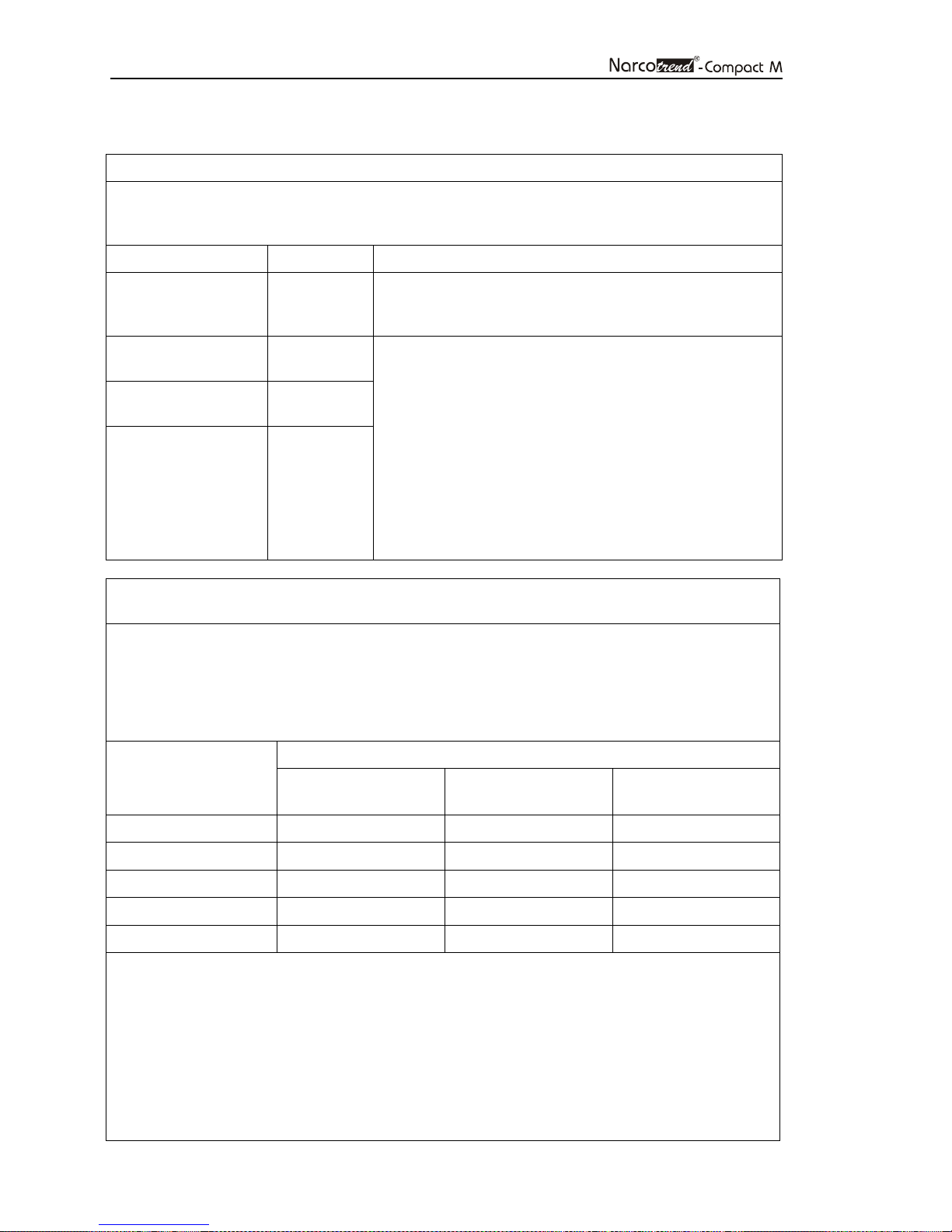
Recommended separation distances between portable and mob
ile
Separation distance according to frequency of transmitter [m]
150 kHz to 80 MHz
80 MHz to 800 MHz
800 MHz to 2,5 GHz
9.4 EMC-Guidance
The Narcotrend-Compact M is intended for use in the electromagnetic environment specified
below. The customer or the user of the Narcotrend-Compact M should ensure that it is used in
such an environment.
RF emissions
CISPR 11
RF emissions
CISPR 11
Harmonic emissions
IEC 61000-3-2
Voltage fluctuations/
flicker emissions
IEC 61000-3-3
RF communications equipment and the Narcotrend-Compact M
The Narcotrend-Compact M is intended for use in an electromagnetic environment in which
radiated RF disturbances are controlled. The customer or the user of the Narcotrend-Compact M
can help prevent electromagnetic interferences by maintaining a minimum distance between
portable and mobile RF communications equipment (transmitters) and the Narcotrend-Compact
M as recommended below, according to the maximum output power of the communications
equipment.
Group 1
Class A
N/A
N/A
The Narcotrend-Compact M must emit electromagnetic
energy in order to perform its intended function. Nearby
electronic equipment could be affected.
The Narcotrend-Compact M is suitable for use in all
establishments other than domestic and those directly
connected to the public low-voltage power supply network
that supplies buildings used for domestic purposes.
The EMISSIONS characteristics of this equipment make it
suitable for use in industrial areas and hospitals (CISPR
11 class A). If it is used in a residential environment (for
which CISPR 11 class B is normally required) this
equipment might not offer adequate protection to radiofrequency communication services. The user might need
to take mitigation measures, such as relocating or reorienting the equipment.
Rated maximum
output power of
transmitter [W]
0.01 0.12 0.12 0.23
0.1 0.38 0.38 0.73
1 1.2 1.2 2.3
10 3.8 3.8 7.3
100 12 12 23
For transmitters rated at a maximum output power not listed above, the recommended
separation distance d in meters can be estimated using the equation applicable to the frequency
of the transmitter, where P is the maximum output power rating of the transmitter in watts (W)
according to the transmitter manufacturer.
NOTE 1 - An additional factor of 10/3 is used in calculating the recommended separation
distance for transmitters in the frequency range 80 MHz to 2,5 GHz to decrease the likelihood
that mobile/portable communications equipment could cause interference if it is inadvertently
brought into patient areas.
NOTE 2 - These guidelines might not apply in all situations. Electromagnetic propagation is
affected by absorption and reflection from structures, objects and people.
d = 1.2√P
d = 1.2√P
d = 2.3√P
Page 45

Page 45
Guidance and manufacturer’s declaration
- electromagnetic immunity
Immunity test
EC 60601 test level
Compliance level
Electromagnetic
1)
1)
The Narcotrend-Compact M is intended for use in the electromagnetic environment specified
below. The customer or the user of the Narcotrend-Compact M should assure that it is used in
such an environment.
environment - guidance
Electrostatic
discharge (ESD)
IEC 61000-4-2
Electrical fast
transient/ burst
IEC 61000-4-4
Surge
IEC 61000-4-5
Voltage dips, short
interruptions and
voltage variations on
power supply input
lines
IEC 61000-4-11
± 8 kV contact
± 15 kV air
± 2 kV for power
supply lines
± 1 kV for input/
output lines
± 1 kV differential
mode
± 2 kV common
mode
0% U
T
for 0.5 cycle
(0, 45, 90, 135, 180,
225, 270, 315
degree)
0% UT
for 1 cycle
(0 degree)
70% UT
for 25/30 cycles
(0 degree)
± 8 kV contact
± 15 kV air
± 2 kV for power
supply lines
± 1 kV for
input/output lines
± 1 kV differential
mode
± 2 kV common
mode
0% U
T
for 0.5 cycle
(0, 45, 90, 135, 180,
225, 270, 315
degree)
0% UT
for 1 cycle
(0 degree)
70% UT
for 25/30 cycles
(0 degree)
Floors should be wood,
concrete, or ceramic tile. If
floors are covered with
synthetic material, the relative
humidity should be at least
30%.
Mains power quality should
be that of a typical
commercial or hospital
environment.
Mains power quality should
be that of a typical
commercial or hospital
environment.
Mains power quality should
be that of a typical
commercial or hospital
environment.
If the user of the Narcotrend-
Compact M requires
continued operation during
power mains interruptions, it
is recommended that the
Narcotrend-Compact M is
powered from an
uninterruptible power supply
or a battery.
Power frequency
3 A/m N/A Power frequency magnetic
(50/60 Hz) magnetic
field
IEC 61000-4-8
NOTE 1 - UT is the AC mains voltage prior to the application of the test level.
fields should be at levels
characteristic of a typical
location in a typical
commercial or hospital
environment.
Page 46
Page 46
Guidance and manufacturer’s declaration
- electromagnetic immunity
Immunity test
IEC 60601 test
Compliance level
Electromagnetic environment
-
watts according to the transmitter
icinity of equipment marked with
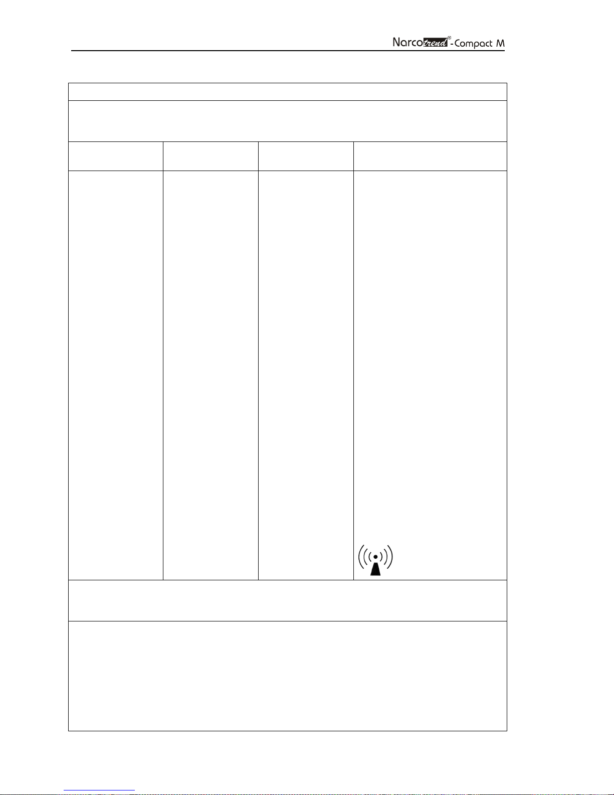
The Narcotrend-Compact M is intended for use in the electromagnetic environment specified
below. The customer or the user of the Narcotrend-Compact M should assure that it is used in
such an environment.
Conducted RF
IEC 61000-4-6
Radiated RF
IEC 61000-4-3
level
3 Vrms
150 kHz to 80 MHz
3 V/m
80 MHz to 5.8 GHz
3 Vrms
3 V/m
guidance
Portable and mobile RF
communications equipment
should be used no closer to any
part of the Narcotrend-Compact
M, including cables, than the
recommended separation
distance calculated from the
equation applicable to the
frequency of the transmitter.
Recommended separation
distance
d = 1.2√P
d = 1.2√P 80 MHz to 800 MHz
d = 2.3√P 800 MHz to 2.5 GHz
Where P is the maximum output
power rating of the transmitter in
manufacturer and d is the
recommended separation
distance in meters.
Field strengths from fixed RF
transmitters, as determined by
an electromagnetic site survey,
should be less than the
compliance level in each
frequency range.
Interference could occur in the
v
the following symbol:
NOTE 1 - At 80 MHz and 800 MHz, the higher frequency range applies.
NOTE 2 - These guidelines might not apply in all situations. Electromagnetic propagation is
affected by absorption and reflection from structures, objects, and people.
Field strengths from fixed transmitters, such as base stations for radio (cellular/cordless)
telephones and land mobile radios, amateur radio, AM and FM radio broadcast, and TV
broadcast cannot be predicted theoretically with accuracy. To assess the electromagnetic
environment due to fixed RF transmitters, an electromagnetic site survey should be considered. If
the measured field strength in the location in which the Narcotrend-Compact M is used exceeds
the applicable RF compliance level above, the Narcotrend-Compact M should be observed to
verify normal operation. If abnormal performance is observed, additional measures may be
necessary, such as reorienting or relocating the Narcotrend-Compact M.
Over the frequency range of 150 kHz to 80 MHz, field strengths should be less than 7 V/m.
Page 47

Page 47
10 List of figures
Fig. 1: EEG index, EEG stages und typical EEG patterns ........................................ 5
Fig. 2: Narcotrend-Compact M, front panel .............................................................. 6
Fig. 3: Narcotrend-Compact M, rear panel ............................................................... 7
Fig. 4: Electrode positions for disposable electrodes, 1-channel (PKM1) ............... 14
Fig. 5: Electrode positions for disposable electrodes, 2-channel (PKM4) ............... 14
Fig. 6: Start screen ................................................................................................ 15
Fig. 7: Recording screen ........................................................................................ 17
Fig. 8: Cerebrogram............................................................................................... 20
Fig. 9: Relative Band Activities / Power, 1-channel and 2-channel ......................... 20
Fig. 10: Quantiles, 1-channel and 2-channel ............................................................ 20
Fig. 11: Power Spectrum, 1-channel and 2-channel ................................................ 21
Fig. 12: DSA, 1-channel and 2-channel ................................................................... 21
Fig. 13: Recording screen during the review mode .................................................. 24
Fig. 14: Set and edit markers ................................................................................... 26
Fig. 15: Menu - Options ........................................................................................... 27
Fig. 16: Dialogue „Review“ ...................................................................................... 31
Fig. 17: Screen “View” (review mode) ...................................................................... 33
 Loading...