

SERIAL #______________________
BUILT-IN CSS610RB INSTRUCTION GUIDE
Please use this manual in conjuction with your main manual to properly assemble your built-in grill. Refer to the
main manual for operating, cleaning, and maintenance instructions. This grill is designed for masonry , noncombustible enclosures only, and must be installed and serviced by a qualified installer to local codes.
BUILT IN PROPANE GAS HOOK-UP: The piping up to the gas grill is the responsibility of the installer and piping should be located as
shown in the built-in instructions. Do not use hose to connect the unit. It must be connected with either rigid pipe, copper tube or an
approved flexible metal connector. The installation must comply with CAN B149.1 Natural Gas and Propane installation code in
Canada, or to the National Fuel Gas code, ANSI Z223.1 in the United States. The minimum recommended piping size is NPS 1/2"
for rigid pipe, and 1/2" OD for copper tubing (based on a 20 ft run). Longer runs may require larger sizes to conform with CAN
B149.1. Propane Gas Installation Code in Canada or to the National Fuel Gas Code, ANSI Z223.1 in the United States. The gas
supply must be connected to the 3/8” flare fitting located under the left hand side of the control panel. If the enclosure is to house a
propane cylinder, the tank portion of the enclosure must be ventilated according to local codes, and must not have communication
with the cavity used to enclose the gas grill. The tank can not be stored below the gas grill.
BUILT IN NATURAL GAS HOOK-UP: The piping up to the gas grill is the responsibility of the installer and piping should be located as
shown in the built-in instructions. Do not use hose to connect the unit. It must be connected with either rigid pipe, copper tube or an
approved flexible metal connector. The installation must comply with CAN B149.1 Natural Gas and Propane Installation Code in
Canada, or to the National Fuel Gas Code, ANSI Z223.1 in the United States. The minimum recommended piping size is NPS 1/2"
for rigid pipe, and 5/8" OD for copper tubing (based on a 20 ft run). Longer runs may require larger sizes to conform with CAN
B149.1. Natural Gas Installation Code in Canada or to the National Fuel Gas Code, ANSI Z223.1 in the United States.
Built in units are supplied with a drip pan which holds only a minimal amount of grease. T oprevent grease fires, the panmust
be cleaned after each use. Access must be provided to the inside of the enclosure to make gas connections.
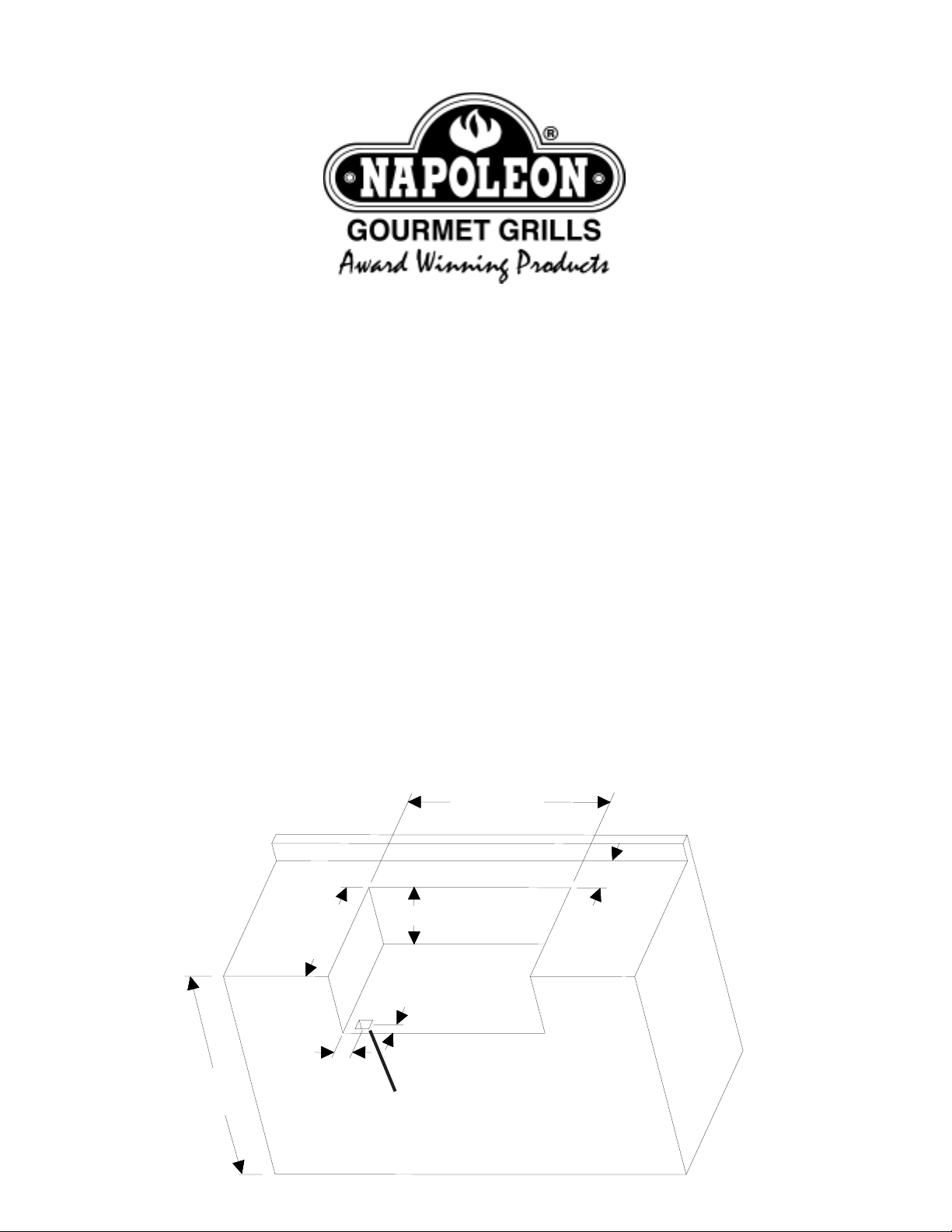
32”
6”MIN
20 ¼”
2 ½”
34”
RECOMMENDED
9 ¾”
2”
GASINLET
OPENING
N415-0147/JAN12/06

BUILT-INACCESSORYOPENING DIMENSIONS
NOTE:ACCESSORYFRAMES OVERLAP
OPENINGBY 1½” ONALL4SIDES
D
H
W
Part #
N370-0069 Flat vertical painted door
N370-0071
N370-0070
N370-0072
N370-0356SS Curved stainless steel door - 308 size
Flat vertical stainless steel door
Flat horizontal painted door
Flat horizontal stainless steel door
Description
Picture
OPENINGDIMENSION
WH
13¼”
18¼”
D
13¼” 18¼”
18¼” 13 ¼”
18¼” 13 ¼”
22½” 19 ¾”
N370-0357SS
N370-0358SS
N370-0361 PF style stainless steel door
N370-0359 PF style stainless steel single drawer
N370-0360 PF style stainless steel triple drawer
Curved stainless steel door - 450 size
Curved stainless steel double door - 600 size
27” 19 ¾”
35¼” 19”
17”
23¼”
17¼” 6 ¾”
17¼” 22 ¾”
23”
23”

GASINLET
OPENING
1. Lower the unit into the opening. Feed the gas flex connector and regulator down through the opening on the left hand
side (natural gas only).
2. For natural gas units, mount the regulator to the cabinet. Connect the gas supply to the inlet side of the regulator. For
propane units, connect the gas supply to the 3/8” flare fitting located on the left side of the manifold tube.
3. Leak test the entire installation before operating the unit.

BUILT-IN ACCESSORY DRAWER INSTRUCTIONS
1.Unpackthedrawerframeassembly.
2.Remove the drawers from the enclosure by fully extending them and then liftinguptoremovethemfrom the slides.
3. Shim the opening to ensure that the enclosure fits snuggly into the opening. Ensure that the side shims are located at
the same height as the enclosure mounting holes. The bottom of the opening may need to be shimmed as well to ensure
that the front of the enclosure is plumb.
4. Once the enclosure islevel and square, fasten into place. (Fasteners not included).
5. Re-install the drawers by tipping the back of the drawer down into the slide. Once the wheels are inserted into the slide,
lower the front of the drawer until it is level, then push in. Note: if the enclosure is installed with shims that are too thick, the
wheel will not engage into the slide. The shim thickness will need to be reduced.
6.Removetheprotectivecoatingfromallremainingsurfaces.
BUILT-IN ACCESSORY DOOR INSTRUCTIONS
1. Unpack the door and frame.
a. For the curved stainless steel doors, removethedoor(s) from the frame by lifting the doorwhileholding on to the pivot
rod. This will allow the pivot rodto come out of the hole on the bottom of the frame. Once the pivot is removed from the
bottomhole, the entire door can be dropped and removed from theframe.
b. For the PF style stainless steel door, the door needs to be removed by loosening the center philips screw on the hinge
furthest away from the door. This will allow the hinge to separate.
2. Center the frame in the opening. Mark the location of the pivot holes,top and bottom. Remember on the PT600 double
doors, there will be a pivot rod on both ends. The PF style doors do not have pivotrods. Once all pivot holes are marked,
remove the frame and using a3/8” drill bit, drill out the clearanceholes for the pivot rod. Theseclearance holes should be
at least 1/2” deep. After the holes are complete, you may once again center the frame in the opening. Starting with the
hinged side, shim between the frame and side wall of the opening. Ensure the shims are close to the hinge on the PF style
doors. When the frame side wall is plumb, fasten it to the cabinet with screws (not provided). Attach the other side of the
frame in the same fashion, ensuring the frameissquare.
3. Other than on the curved stainless steel doubledoor kit, fasteners arenot required on the top and bottom of theframe.
The curved stainless steel double door frame must be fastened in the centerboth at the top and bottom.
4. Once the frame has been securedand checked for squareness, the door canbe re-installed.
5.Remove the protective coating from all remaining surfaces.
 Loading...