

Page 1
INSTALLER: LEAVE THIS MANUAL WITH THE APPLIANCE.
CONSUMER: RETAIN THIS MANUAL FOR FUTURE REFERENCE.
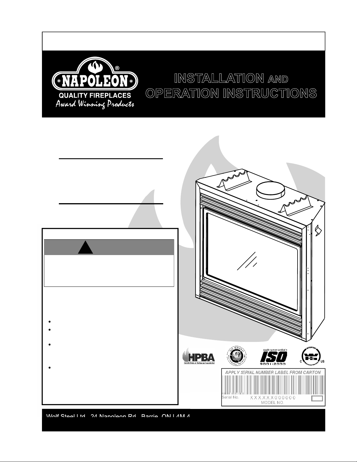
INSTALLATION AND
OPERATION INSTRUCTIONS
CERTIFIED UNDER CANADIAN AND AMERICAN NATIONAL STANDARDS: CSA 2.33 ● ANSI Z21.88 FOR VENTED GAS FIREPLACE HEATERS.
GD36NTR
BGD36NTR
NATURAL GAS MODEL
GD36PTR
1
BGD36PTR
PROPANE GAS MODEL
CERTIFIED FOR CANADA AND UNITED STATES USING ANSI/CSA METHODS.
SAFETY INFORMATION
!
WARNING
If the information in these instructions are
not followed exactly, a fire or explosion
may result causing property damage,
personal injury or loss of life.
- Do not store or use gasoline or other
flammable vapors and liquids in the vicinity
of this or any other appliance.
- WHAT TO DO IF YOU SMELL GAS:
Do not try to light any appliance.
Do not touch any electrical switch; do
not use any phone in your building.
Immediately call your gas supplier from
a neighbor's phone. Follow the gas
supplier’s instructions.
If you cannot reach your gas supplier,
call the fire department.
- Installation and service must be
performed by a qualified installer, service
agency or the supplier.
B
GD36 I
l
l
ust
rated
Wolf Steel Ltd., 24 Napoleon Rd., Barrie, ON L4M 4Y8 Canada • (705)721-1212 • fax(705)722-6031
www.napoleonfireplaces.com • ask@napoleon.on.ca
$10.00
W415-0210 / R / 02.27.08
Page 2
2
TABLE OF CONTENTS
PG 2-5 INTRODUCTION
Warranty
General Instructions
General Information
Care of Glass and Plated Parts
Specifi cations
5-16 VENTING
Venting Lengths
Vent Installations
Typical Vent Installations
Special Vent Installations
Minimum Air Terminal Location Clearances
Venting Application Flow Chart
Venting Specifi cations
Pre-Installation Preparation
17-26 INSTALLATION
Wall and Ceiling Protection
Horizontal Installation
Vertical Installation
Using Flexible Vent Components
Fireplace Vent Connection
Using Rigid Vent Components
Vertical Venting Installation
Restricting Vertical Vents
Mobile Home Installation
Gas Installation
Optional Wall Switch Installation
Framing
Minimum Enclosure Clearances
Minimum Mantel Clearances
Nailing Tab Installation
27-28 FINISHING
Door Removal & Installation
Door Glass Replacement
L36 Louvre Installation
Log Placement
Logo Placement
29
OPTIONAL BLOWER INSTALLATION
30 OPTIONAL FAN INSTALLATION
OPTIONAL THERMOSTATIC SENSOR
31 OPERATION / MAINTENANCE
Operating Instructions
Maintenance
30 ADJUSTMENTS
Pilot Burner Adjustment
Venturi Adjustment
32-34 REPLACEMENTS
Ordering Replacement Parts
Replacement Parts
Accessories
35-36 TROUBLE SHOOTING GUIDE
37 SERVICE HISTORY
38 NOTES
RETAIN THIS MANUAL FOR FUTURE REFERENCE
!
WARNING
• Do not burn wood or other materials in this fi replace.
• Adults and especially children should be alerted to the hazards of high surface temperatures and should stay away to avoid burns or
clothing ignition. Supervise young children when they are in the same room as the fi replace.
• Clothing or other fl ammable material should not be placed on or near the fi replace.
• Due to high temperatures, the fi replace should be located out of traffi c and away from furniture and draperies.
• Ensure you have incorporated adequate safety measure to protect infants/toddlers from touching hot surfaces.
• Even after the fi replace is out, the glass and/or screen will remain hot for an extended period of time.
• Check with your local hearth specialty dealer for safety screens and hearth guards to protect children from hot surfaces. These screens
and guards must be fastened to the fl oor.
• Any safety screen or guard removed for servicing must be replaced prior to operating the fi replace.
• It is imperative that the control compartments, burners and circulating blower and its passageway in the fi replace and venting system
are kept clean. The fi replace and its venting system should be inspected before use and at least annually by a qualifi ed service person.
More frequent cleaning may be required due to excessive lint from carpeting, bedding material, etc. The fi replace area must be kept clear
and free from combustible materials, gasoline and other fl ammable vapours and liquids.
• Under no circumstances should this fi replace be modifi ed.
• This fi replace must not be connected to a chimney fl ue pipe serving a separate solid fuel burning appliance.
• Do not use this fi replace if any part has been under water. Immediately call a qualifi ed service technician to inspect the fi replace and to
replace any part of the control system and any gas control which has been under water.
• Do not operate the fi replace with the glass door removed, cracked or broken. Replacement of the glass should be done by a licensed
or qualifi ed service person.
• Do not strike or slam shut the fi replace glass door.
• This fi replace uses and requires a fast acting thermocouple. Replace only with a fast acting thermocouple supplied by Wolf Steel Ltd.
• Pressure relief doors must be kept closed while the fi replace is operating to prevent exhaust fumes containing carbon monoxide, from
entering into the home. Temperatures of the exhaust escaping through these openings can also cause the surrounding combustible
materials to overheat and catch fi re.
• Only doors / optional fronts certifi ed with the unit are to be installed on the appliance.
NOTE: CHANGES, OTHER THAN EDITORIAL, ARE DENOTED BY A VERTICAL LINE IN THE MARGIN.
W415-0210 / R / 02.27.08
Page 3
3
®
®
®
®
®
®
®
®
®
®
®
®
®
®
®
®®
®
®
®
®
W415-0210 / R / 02.27.08
Page 4
4
GENERAL INSTRUCTIONS
THIS GAS FIREPLACE SHOULD BE INSTALLED AND SERVICED BY A QUALIFIED INSTALLER to conform with local
codes. Installation practices vary from region to region and it is important to know the specifi cs that apply to your area,
for example: in Massachusetts State:
• The fi replace damper must be removed or welded in the open position prior to installation of a fi replace insert or gas log.
• A carbon monoxide detector is required in all rooms containing gas fi red appliances
• The appliance off valve must be a “T” handle gas cock.
• The fl exible connector must not be longer than 36".
• The appliance is not approved for installation in a bedroom or bathroom unless the unit is a direct vent sealed combustion product.
• WARNING: This product must be installed by a licensed plumber or gas fi tter when installed within the commonwealth of
Massachusetts.
In absence of local codes, install to the current National Fuel Gas Code, ANSI Z223.1, or the current CAN/CGA B149, Installation
Codes. Mobile home installation must conform with local codes or in the absence of local codes, install to the current standard
for gas equipped mobile housing CAN/CSA ZA240 MH Series in Canada or the Manufactured Home Construction and Safety
Standard, Title 24 CFR, Part 3280, or the Fire Safety Criteria for Manufactured Home Installations, Sites and Communities
Standard ANSI/NFPA 501A in the United States.
The fi replace and its individual shutoff valve must be disconnected from the gas supply piping system during any pressure
testing of that system at test pressures in excess of 1/2 psig (3.5 kPa). The fi replace must be isolated from the gas supply
piping system by closing its individual manual shutoff valve during any pressure testing of the gas supply piping system at test
pressures equal to or less than 1/2 psig (3.5 kPa).
When the fi replace is installed directly on carpeting, vinyl tile or other combustible
material other than wood fl ooring, the fi replace shall be installed on a metal or
wood panel extending the full width and depth.
If the optional fan or blower is installed, the junction box must be electrically
connected and grounded in accordance with local codes. In the absence of local
codes, use the current CSA C22.1 CANADIAN ELECTRICAL CODE in Canada
or the ANSI/NFPA 70 NATIONAL ELECTRICAL CODE in the United States.
GENERAL INFORMATION
FOR YOUR SATISFACTION, THIS FIREPLACE HAS BEEN TEST-FIRED TO ASSURE ITS OPERATION AND QUALITY!
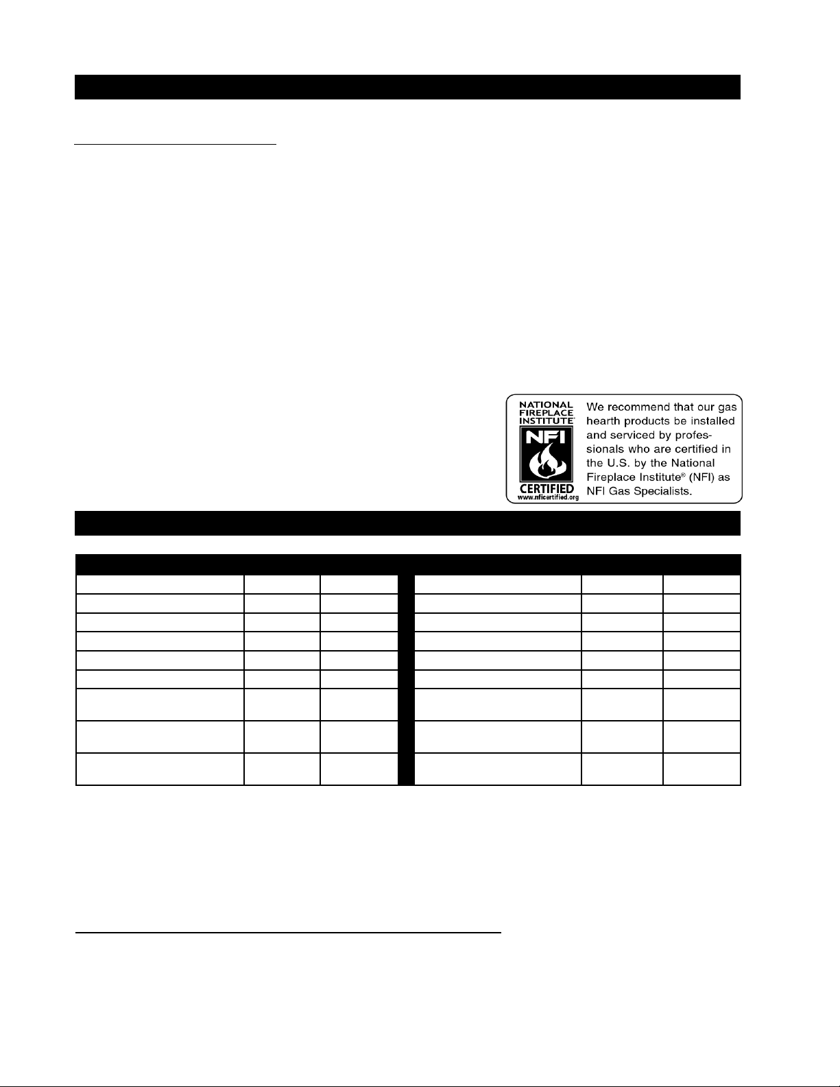
GD36 RATES AND EFFICIENCIES BGD36 RATES AND EFFICIENCIES
NG LP NG LP
ALTITUDE (FT) 0 - 4,500 0 - 4,500 ALTITUDE (FT) 0 - 4,500 0 - 4,500
MAX. INPUT (BTU/HR) 26,000 26,000 MAX. INPUT (BTU/HR) 18,000 17,000
MAX. OUTPUT (BTU/HR) 22,360 22,880 MAX. OUTPUT (BTU/HR) 11,500 10,900
EFFICIENCY (w/ the fan on) 86% 88% EFFICIENCY (w/ the fan on) 64% 64%
A.F.U.E. 64% 65% A.F.U.E. 53% 53%
MINIMUM INLET GAS SUPPLY
PRESSURE
MAXIMUM INLET GAS SUPPLY
PRESSURE
MANIFOLD PRESSURE
(under fl ow conditions)
This fi replace is approved for bathroom, bedroom and bed-sitting room installations and is suitable for mobile home
installation.
No external electricity (110 volts or 24 volts) is required for the gas system operation.
Expansion / contraction noises during heating up and cooling down cycles are normal and are to be expected.
Provide adequate ventilation air. Provide adequate accessibility clearance for servicing and operating the fi replace.
Never obstruct the front opening of the fi replace.
Objects placed in front of the fi replace must be kept a minimum of 48" away from the front face of the unit.
Use only Napoleon® accessories designed for and listed with the model.
4.5" WATER
COLUMN
7" WATER
COLUMN
3.5" WATER
COLUMN
11" WATER
COLUMN
13" WATER
COLUMN
10" WATER
COLUMN
MINIMUM INLET GAS SUPPLY
PRESSURE
MAXIMUM INLET GAS SUPPLY
PRESSURE
MANIFOLD PRESSURE
(under fl ow conditions)
4.5" WATER
COLUMN
7" WATER
COLUMN
3.5" WATER
COLUMN
11" WATER
COLUMN
13" WATER
COLUMN
10" WATER
COLUMN
W415-0210 / R / 02.27.08
Page 5
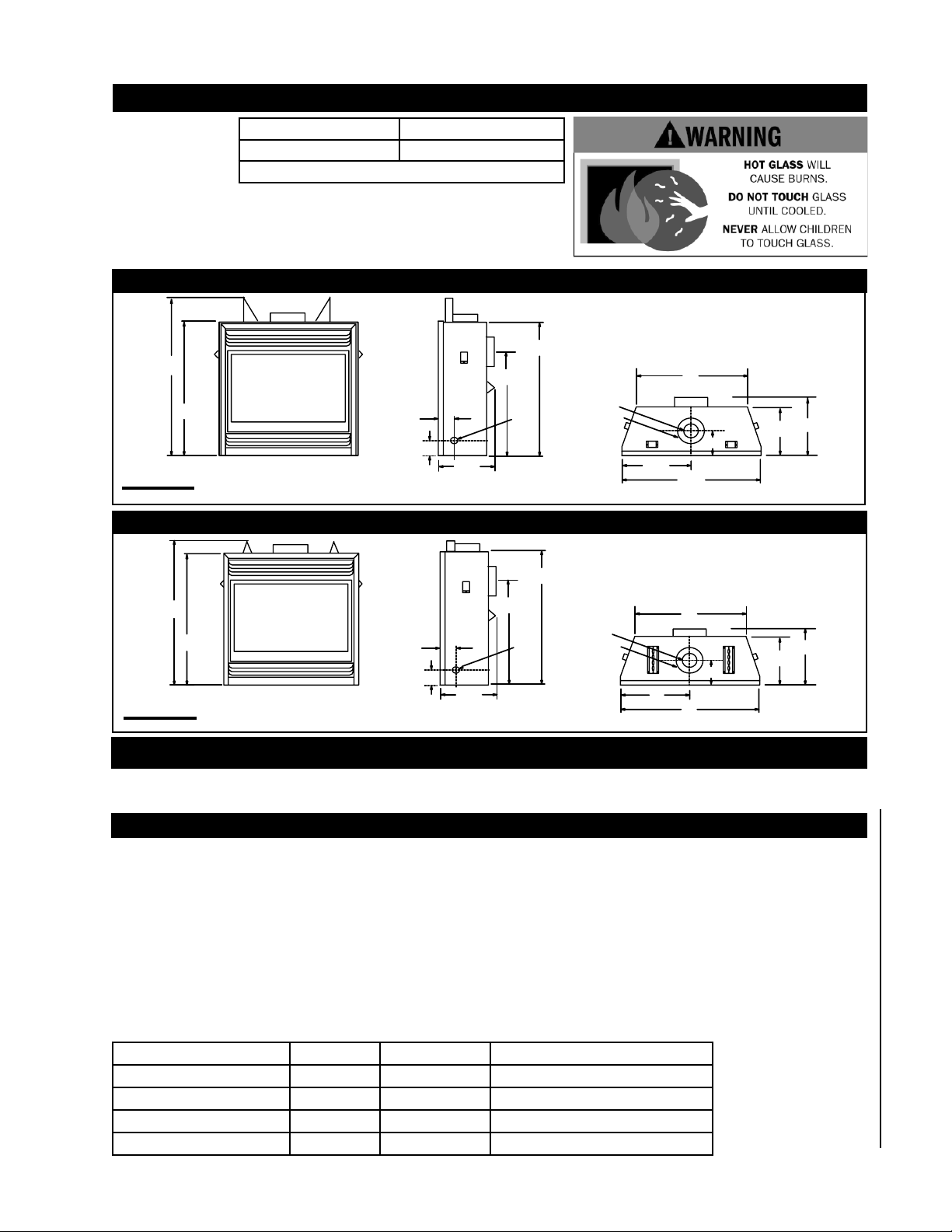
CARE OF GLASS AND PLATED PARTS
Do not use abrasive
cleaners to clean
plated parts. Buff
lightly with a clean
dry cloth.
DO NOT SUBSTITUTE MATERIALS. Clean the glass after the fi rst 10 hours
of operation with a recommended gas fi replace glass cleaner. Thereafter
clean as required. DO NOT CLEAN GLASS WHEN HOT! If the glass is not
kept clean permanent discolouration and / or blemishes may result.
GD36 GLASS TYPE BGD36 GLASS TYPE
3/16" Ceramic Glass* 3/16" Tempered Glass*
*Available from your Napoleon® / Wolf Steel Ltd. dealer.
GD36 SPECIFICATIONS
323/8"
381/2"
33"
FIGURE 1a
1
5
/2"
3"
141/4"
ELECTRICAL INLET
LEFT SIDE
24
1
/4"
GAS
INLET
4" DIA.
7" DIA.
18
5
27"
1
1
14
1
7
/2"
5
/8"
1
37
/4"
12
/4"
/4"
BGD36 SPECIFICATIONS
323/8"
1
/4"
14
24
4" DIA.
GAS
7" DIA.
INLET
1
/4"
18"
27"
1
14
/4"
1
12
1
/2"
7
/4"
36"
351/2"
32
FIGURE 1b
3
/8"
1
5
/2"
3"
ELECTRICAL INLET
LEFT SIDE
VENTING
MODELS GD36 AND BGD36 MAY BE VENTED EITHER AS A TOP VENT OR A REAR VENT.
REFER TO THE SECTION APPLICABLE TO YOUR INSTALLATION.
VENTING LENGTHS
Use only Wolf Steel, Simpson Dura-Vent, Selkirk Direct Temp, American Metal Amerivent, or SuperSeal venting components.
Minimum and maximum vent lengths, for both horizontal and vertical installations, and air terminal locations for either system
are set out in this manual and must be adhered to. For Simpson Dura-Vent, Selkirk Direct Temp, American Metal Amerivent,
and SuperSeal follow the installation procedure provided with the venting components.
All outer pipe joints of these venting systems must be sealed using Red RTV and/or Mill Pac high temperature sealant (not
supplied) hereafter referred to as high temperature sealant W573-0002 (Red RTV) and the high temperature sealant W5730007 (Mill Pac).
The connection between the adaptor and for these systems and the fi replace fl ue collar must be sealed using the high
temperature sealant W573-0007 Mill Pac (not supplied).
A starter adaptor must be used with the following vent systems and may be purchased from the corresponding
supplier:
PART 4" / 7" SUPPLIER WEBSITE ADDRESS*
Simpson Dura-Vent W175-0053 Wolf Steel Ltd. www.duravent.com
Selkirk Direct Temp 4DT-AAN Selkirk www.selkirkcorp.com
American Metal Amerivent 4DSC-N2 American Metal www.americanmetalproducts.com
SuperSeal 4DNA Metal-Fab www.mtlfab.com
* For Simpson Dura-Vent,
Selkirk Direct Temp,
merican Metal Amerivent,
and SuperSeal follow the
installation procedure
found on the website for
your venting supplier.
W415-0210 / R / 02.27.08
Page 6
6
For vent systems that provide seals on the inner exhaust fl ue, only the outer air intake joints must be sealed using a red high
temperature silicone (RTV). This same sealant may be used on both the inner exhaust and outer intake vent pipe joints of all
other approved vent systems except for the exhaust vent pipe connection to the fi replace fl ue collar which must be sealed
using the black high temperature sealant Mill Pac.
When using Wolf Steel venting components, use only approved Wolf Steel rigid / fl exible components with the following
termination kits: WALL TERMINAL KIT GD222, or 1/12 TO 7/12 PITCH ROOF TERMINAL KIT GD110, 8/12 TO 12/12 ROOF
TERMINAL KIT GD111 , FLAT ROOF TERMINAL KIT GD112 or PERISCOPE KIT GD201 (for wall penetration below grade).
With fl exible venting, in conjunction with the various terminations, use either the 5 foot vent kit GD220 or the 10 foot vent
kit GD330.
For optimum fl ame appearance and fi replace performance, keep the vent length and number of elbows to a
minimum.
The air terminal must remain unobstructed at all times. Examine the air terminal at least once a year to verify that
it is unobstructed and undamaged.
Wolf Steel rigid and fl exible venting systems must not be combined.
Wolf Steel, Simpson Dura-Vent, Selkirk Direct Temp and American Metal Amerivent venting systems must not be
combined.
These vent kits allow for either horizontal or vertical venting of the fi replace. The maximum allowable horizontal run is 20
feet.
The maximum allowable vertical vent length is 40 feet. The maximum number of 4" vent connections is two horizontally or
three vertically (excluding the fi replace and the air terminal connections) when using fl exible vent pipe.
For optimum performance, it is recommended that all horizontal runs have a 1" rise per foot.
GD36 REQUIRED RISE ON HORIZONTAL VENTING BGD36 REQUIRED RISE ON HORIZONTAL VENTING
REAR VENT
TOP VENT
CORNER VENT
RIGID VENTING 1" / FT **
FLEXIBLE VENTING 1" / FT ** FLEXIBLE VENTING 0" / FT
RIGID VENTING 0" / FT
FLEXIBLE VENTING 0" / FT FLEXIBLE VENTING 0" / FT
RIGID VENTING 6"
FLEXIBLE VENTING 6" FLEXIBLE VENTING 6"
REAR VENT
TOP VENT
CORNER VENT
** When a vertical rise is used as part of the venting confi guration, a 0" rise per foot is acceptable.
RIGID VENTING 0" / FT
RIGID VENTING 0" / FT
RIGID VENTING 0"
VENT INSTALLATIONS
For safe and proper operation of the fi replace follow the venting instructions exactly.
Deviation from the minimum or maximum vertical vent length can create diffi culty in burner start-up and/or
carboning.
Under extreme vent confi gurations, allow several minutes (5-15) for the fl ame to stabilize after ignition.
Vent lengths that pass through unheated spaces (attics, garages, crawl spaces) should be insulated with the
insulation wrapped in a protective sleeve to minimize condensation.
Provide a means for visually checking the vent connection to the fi replace after the fi replace is installed.
Use a fi restop, vent pipe shield or attic insulation shield when penetrating interior walls, fl oor or ceiling.
GD36 BGD36
HORIZONTAL VENT SECTIONS
A minimum clearance of 1" at the bottom and sides and 2" at
the top of the vent pipe on all horizontal runs to combustibles
is required. Use fi restop spacer W010-1777 (supplied).
VERTICAL VENT SECTIONS
A minimum of 1" all around the vent pipe on all vertical runs
to combustibles is required except for clearances in fi replace
enclosures. See "Minimum Enclosure Clearances" section.
Use fi restop spacer W500-0096 (not supplied).
A minimum clearance of 1" at the bottom and sides and 2" at
the top of the vent pipe on all horizontal runs to combustibles
is required. Use fi restop spacer W010-1774 (supplied).
A minimum of 1" all around the vent pipe on all vertical runs
to combustibles is required except for clearances in fi replace
enclosures. See "Minimum Enclosure Clearances" section.
HORIZONTAL VENT SECTIONS
VERTICAL VENT SECTIONS
Use fi restop spacer W500-0096 (not supplied).
W415-0210 / R / 02.27.08
FOR SPECIFIC VENTING PARAMETERS, REFER TO PAGES 10-15
Page 7
TYPICAL VENT INSTALLATIONS (GD36 AND BGD36)
M
16”
MINIMUM
FIGURE 2a FIGURE 2b
TOP EXITREAR EXIT
16”
MINIMUM
7
40 FT MAXIMUM
20" MAXIMUM
1
/4" MINIMUM
24
PLUS RISE*
* See chart on Page 6
FIGURE 2c
FIGURE 2d
3 FT MINIMUM
GD36
MINIMUM
24"
33"
24" MAXIMUM
57" MINIMUM
PLUS RISE**
40 FT MAXIMUM
3 FT MINIMUM
20" MAXIMUM
1
24
/4" MINIMUM
PLUS RISE*
* See chart on Page 6
FIGURE 2e
BGD36
MINIMUM
FIGURE 2f
10"
32 3/8"
24" MAXIMUM
3
42
/8" MINIMUM
PLUS RISE**
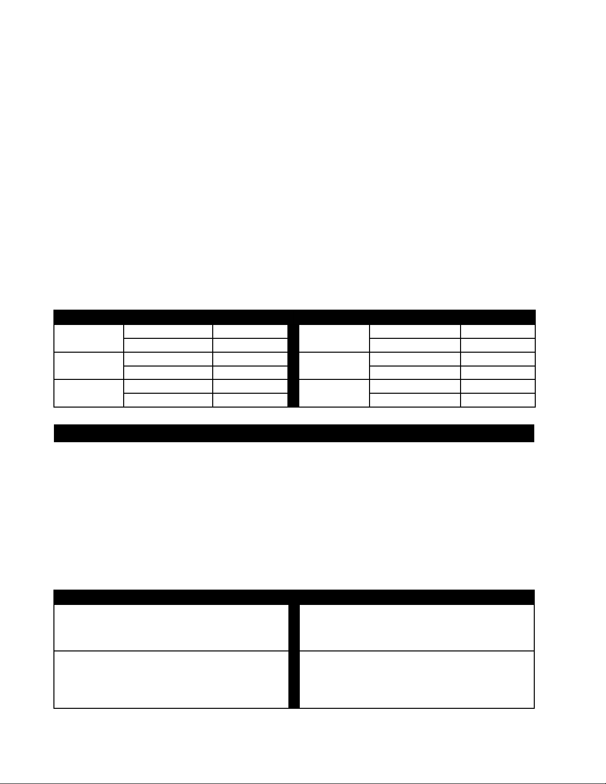
SPECIAL VENT INSTALLATIONS
PERISCOPE TERMINATION
(GD36 AND BGD36)
Use the GD201 periscope kit to locate the air termination
above grade. The periscope must be installed so that when
fi nal grading is completed, the bottom air slot is located a
minimum of 12" above grade. The maximum allowable vent
length is 10 feet.
FIGURE 3a
30”
MINIMUM
MAXIMUM 10FT VENT LENGTH
TOP EXIT INSTALLATION
12”
MINIMUM
30”
MINIMUM
REAR EXIT INSTALLATION
FIGURE 3b
12”
MINIMUM
CORNER TERMINATION
GD36 BGD36
The maximum vent length
for a corner installation
is 24", where only 6" of
vertical rise is used. All
corner installations require
a minimum 6" rise. See
FIGURE 4a.
FIGURE 4a
6” RISE
MINIMU
The maximum vent length for
a corner installation is 20" of
horizontal run, in addition to
the 45° offset. In this case
0" rise is acceptable when
using rigid. See FIGURE
4b. Flexible venting must
maintain a 6" rise. See
FIGURE 4a.
20” MAXIMUM
FIGURE 4b
(BGD36 ONLY)
(WITH RIGID ONLY)
W415-0210 / R / 02.27.08
Page 8
8
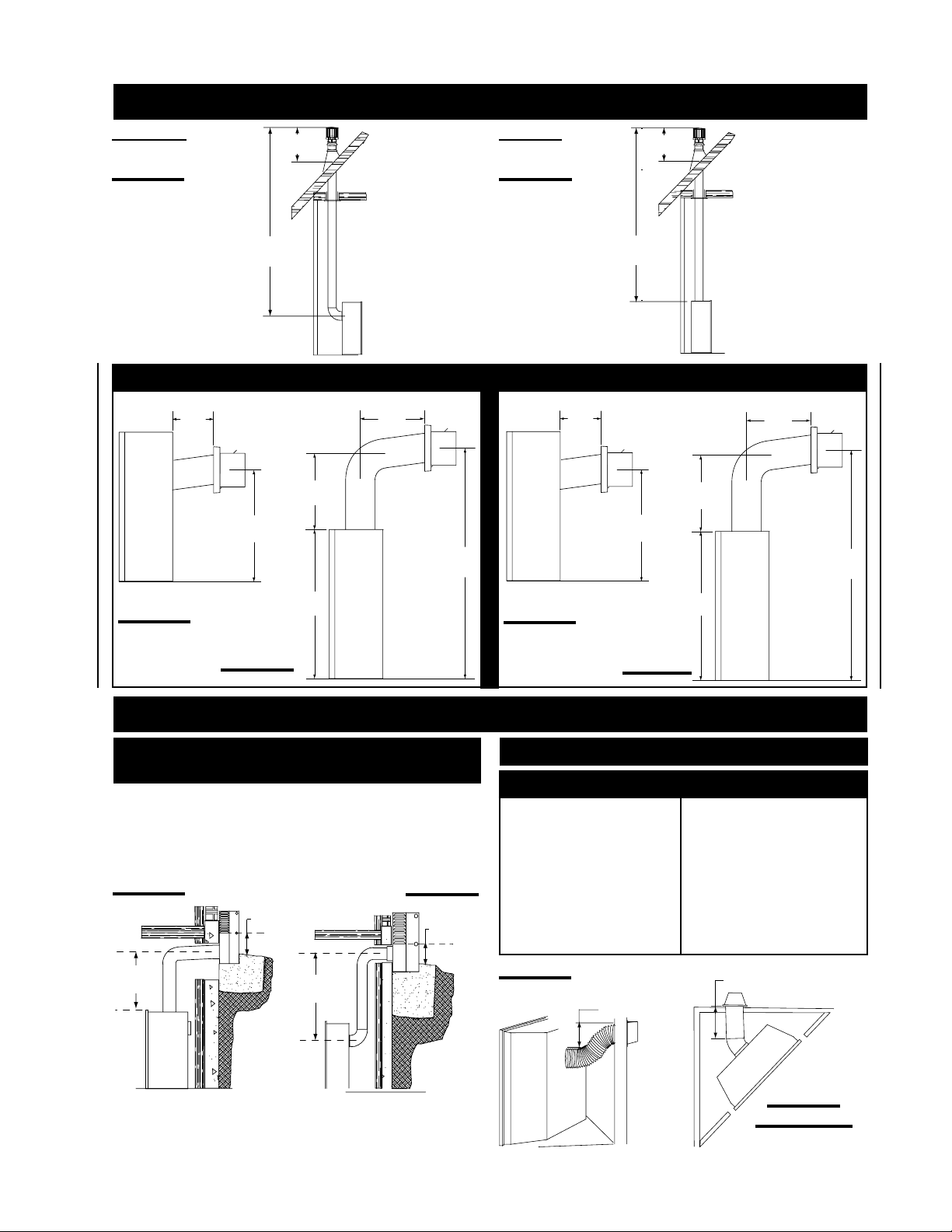
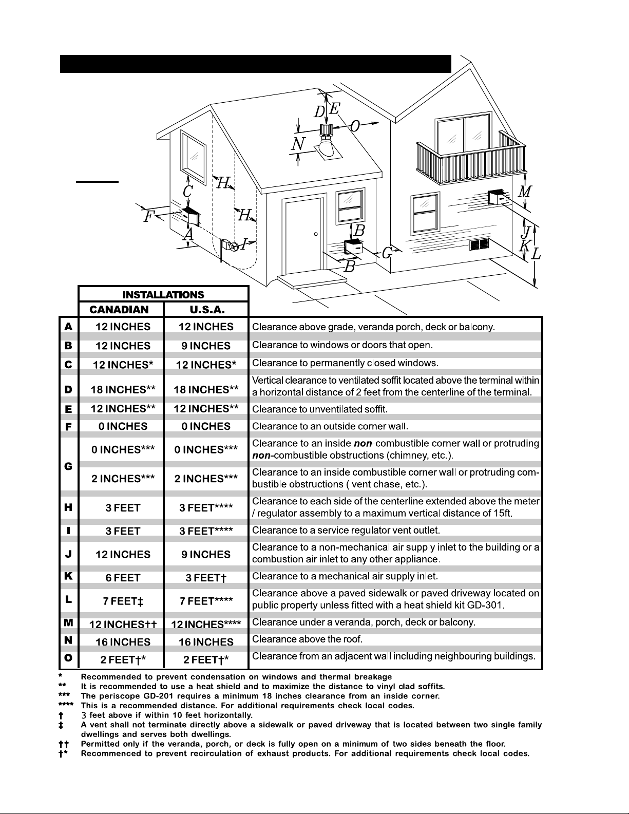
MINIMUM AIR TERMINAL LOCATION CLEARANCES
FIGURE 5
W415-0210 / R / 02.27.08
Page 9
TOP EXIT
Vertical rise
Vertical Termination
Vertical rise
is less than
horizontal
run
Vertical rise
is equal to
or greater
than the
is less than
horizontal
run
9
Horizontal
run + verti-
cal rise to
maximum
of 40 feet
horizontal
run
Horizontal
run + verti-
cal rise to
Horizontal
run + verti-
cal rise to
maximum of
maximum
of 40 feet
24.75 feet
3 times the
vertical rise
equal to or
greater than
the horizon-
4.2 times the
vertical rise
equal to or
greater than
the horizon-
tal run
tal run
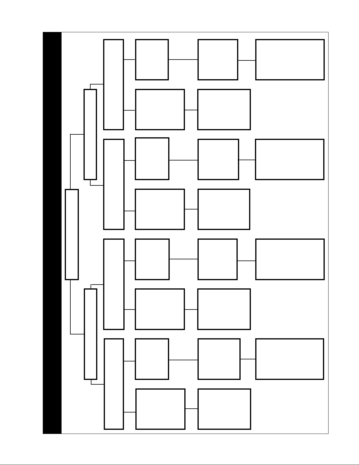
VENTING APPLICATION FLOW CHART
Horizontal Termination
FIREPLACE VENT EXIT
Vertical Termination
REAR EXIT
Vertical rise
is equal to
or greater
than the
Vertical rise
is less than
horizontal
Vertical rise
is equal to
or greater
than the
Vertical rise
is less than
horizontal
horizontal
run
horizontal
run
run
run
Horizontal
run + verti-
cal rise to
Horizontal
run + verti-
cal rise to
Horizontal
run + verti-
cal rise to
Horizontal
run + verti-
cal rise to
maximum of
maximum
of 40 feet
maximum
of 40 feet
maximum
of 40 feet
24.75 feet
3 times the
vertical rise
equal to or
greater than
the horizon-
3.5 times the
vertical rise
equal to or
greater than
the horizon-
tal run
tal run
Horizontal Termination
Vertical rise
is equal to
or greater
than the
horizontal
run
Horizontal
run + verti-
cal rise to
maximum
of 40 feet
W415-0210 / R / 02.27.08
Page 10
10
DEFINITIONS
for the following symbols used in the venting calculations
and examples are:
> - greater than
> - equal to or greater than
< - less than
< - equal to or less than
- total of both horizontal vent lengths (HR) and offsets
H
T
(HO) in feet
- combined horizontal vent lengths in feet
H
R
- offset factor: .03(total degrees of offset - 90°*) in
H
O
feet
- combined vertical vent lengths in feet
V
T
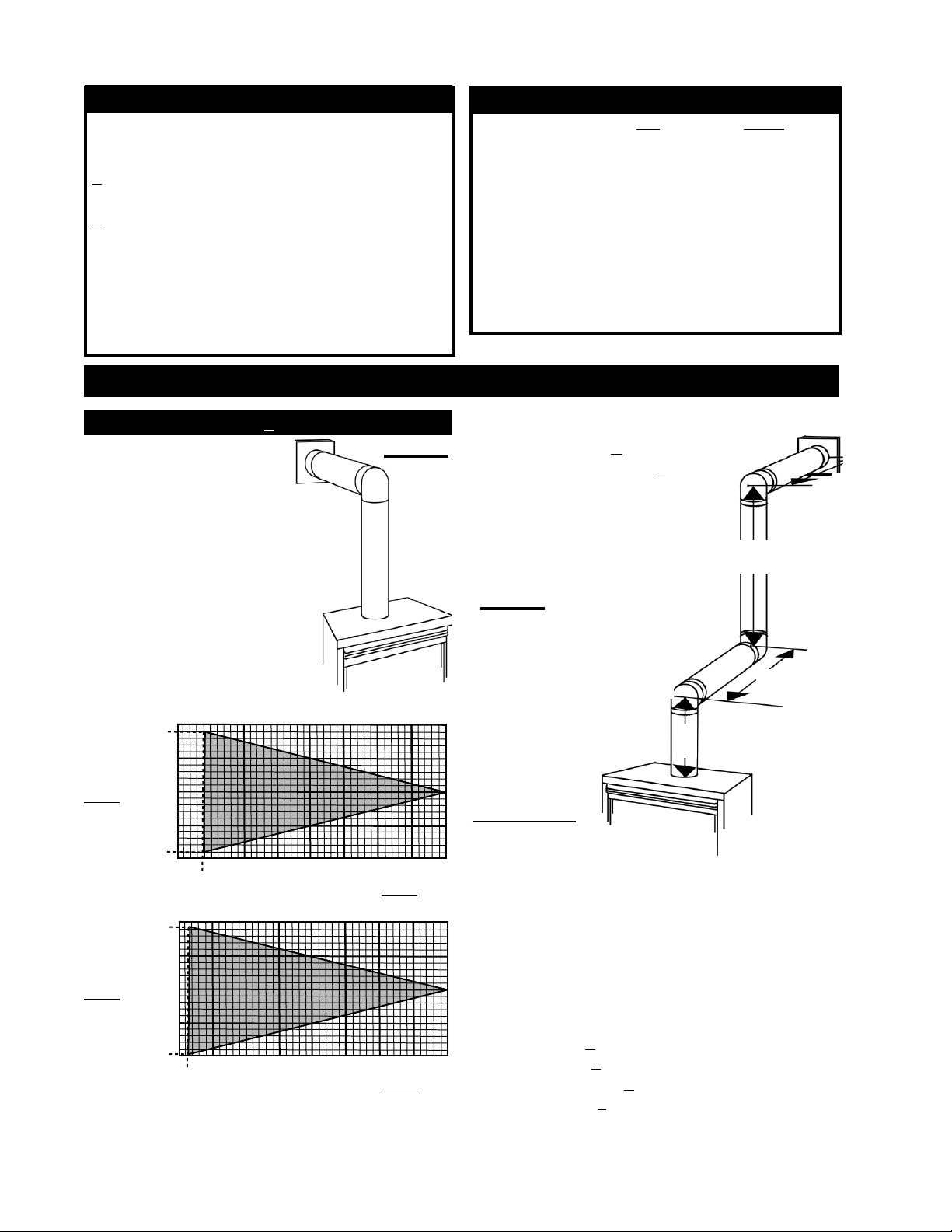
TOP EXIT / HORIZONTAL TERMINATION
(HT) < (VT)
FIGURE 6
Simple venting confi guration
(only one 90° elbow)
ELBOW VENT LENGTH VALUES
feet inches
1° 0.03 0.5
15° 0.45 6.0
30° 0.9 11.0
45° 1.35 16.0
90°* 2.7 32.0
* the fi rst 90° offset has a zero value and is shown in the
formula as -90°
For vent confi gurations requiring more than one 90° elbow,
the following formulas apply:
Formula 1: HT < V
Formula 2: HT + VT < 40 feet
T
90°
H
2
See graph to determine the required
vertical rise VT for the required horizontal run HT.
40
38
REQUIRED
VERTICAL
RISE IN
FEET V
30
20
T
10
2
0
2.5 5 7.5 10 12.5 15
2
HORIZONTAL VENT RUN PLUS OFFSET IN FEET H
40
39.2
REQUIRED
VERTICAL
RISE IN
FEET V
30
20
T
10
.8
0
2.5 5 7.5 10 12.5 15
.8
HORIZONTAL VENT RUN PLUS OFFSET IN FEET H
GD36
17.5 20
T
BGD36
17.5
T
20
The shaded area within the lines represents acceptable
values for HT and V
W415-0210 / R / 02.27.08
.
T
V
2
FIGURE 7
90°
H
90°
V
1
Example 1:
V1 = 3 ft
= 8 ft
V
2
VT =
H1 = 2.5 ft
H
H
H
HT = HR + HO = 4.5 + 5.4 = 9.9 ft
H
Formula 1: H
Formula 2: H
20.9 < 40
Since both formulas are met, this vent confi guration is
acceptable.
V1 +
V2 =
3 + 8 = 11 ft
= 2 ft
2
= H1 + H2 = 2.5 + 2 = 4.5 ft
R
= .
O
T
03(three 90° elbows - 90°) = .03(270° - 90°) = 5.4 ft
+ VT = 9.9 + 11 = 20.9 ft
< V
T
T
9.9 < 11
+ VT < 40 feet
T
1
Page 11
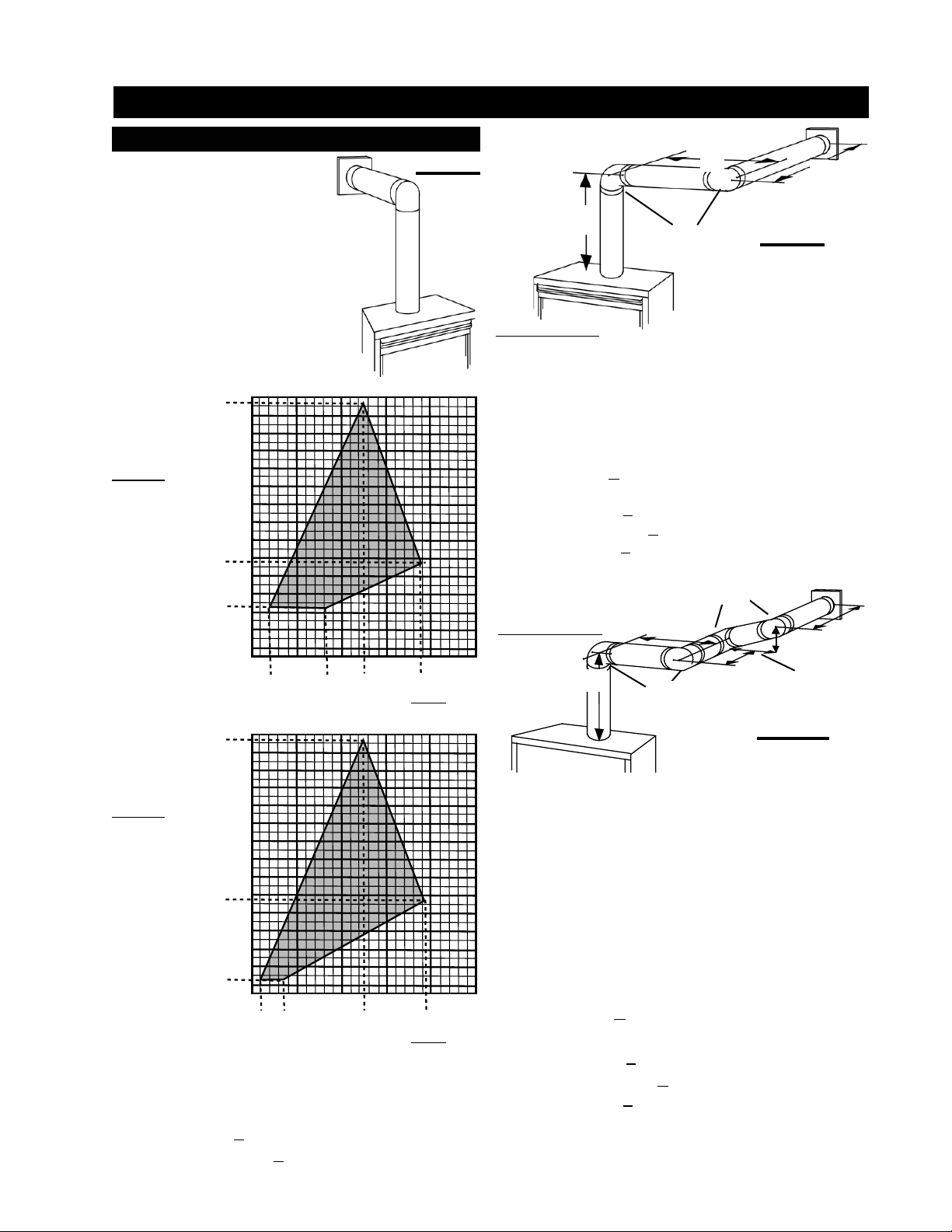
TOP EXIT / HORIZONTAL TERMINATION
11
(HT) > (VT)
FIGURE 8
FIGURE 8
Simple venting confi guration
(only one 90° elbow)
See graph to determine the required
vertical rise VT for the required
horizontal run HT .
GD36
147
150
REQUIRED
VERTICAL
RISE IN
INCHES V
HORIZONTAL VENT RUN PLUS OFFSET IN FEET H
T
147
100
57
50
24
0
150
51525
8.42
19.2512.5
T
BGD36
REQUIRED
VERTICAL
RISE IN
INCHES V
HORIZONTAL VENT RUN PLUS OFFSET IN FEET H
T
100
57
50
10
0
1 19.2512.5
51525
3.5
T
The shaded area within the lines represents acceptable
values for HT and V
.
T
For vent confi gurations requiring more than one 90° elbow the
following formulas apply:
Formula 1: HT < 4.2 V
T
Formula 2: HT + VT < 24.75 feet
H
V
1
1
90°
FIGURE 9
H
2
Example 2:
V
H1 = 3 ft
H2 = 5 ft
HR = H1 + H2 = 3 + 5 = 8 ft
HO = .03(two 90° elbows - 90°) = .03(180° - 90°) = 2.7 ft
HT = HR + HO = 8 + 2.7 = 10.7 ft
HT + VT =
Formula 1: HT < 4.2 V
4.2 V
= VT = 6 ft
1
10.7 + 6 =16.7
T
T
10.7 < 25.2
= 4.2 x 6 = 25.2 ft
Formula 2: HT + VT < 24.75 feet
16.7 < 24.75
Since both formulas are met, this vent configuration is
acceptable.
Example 3:
V
H
1
90°
90°
1
V
H
2
H
H
2
4
3
FIGURE 10
V
1
V
2
= 4 ft
= 1.5 ft
VT = V1 + V2 = 4 + 1.5 = 5.5 ft
H1 = 2 ft
= 1 ft
H
2
= 1 ft
H
3
= 1.5 ft
H
4
HR = H1 + H2 + H3 + H4 = 2 + 1 + 1 + 1. 5 = 5.5 ft
= .03(four 90° elbows - 90°) = .03(360° - 90°) = 8.1 ft
H
O
HT = HR + HO = 5.5 + 8.1 = 13.6 ft
+ VT = 13.6 + 5.5 = 19.1 ft
H
T
Formula 1: HT < 4.2 V
T
4.2 VT = 4.2 x 5.5 = 23.1 ft
13.6 < 23.1
Formula 2: HT + VT < 24.75 feet
19.1 < 24.75
Since both formulas are met, this vent confi guration is
acceptable.
W415-0210 / R / 02.27.08
Page 12

12
REAR EXIT / HORIZONTAL TERMINATION
(HT) < (VT)
Simple venting confi guration
(only two 90° elbows)
FIGURE 11
See graph to determine the required vertical rise VT for the
required horizontal run H
REQUIRED
VERTICAL
RISE IN
FEET V
T
HORIZONTAL VENT RUN PLUS OFFSET IN FEET H
The shaded area within the lines represents acceptable
values for HT and V
For vent confi gurations requiring more than two 90° elbows
the following formulas apply:
Formula 1: HT < V
Formula 2: HT + VT < 40 feet
T
.
T
T
Example 4:
90°
H
V
2
1
FIGURE 12
H
90°
H
2
V
1
90°
V
1
V
2
V
T
H1 = 3 ft
H
2
H
3
HR = H1 + H2 + H3 = 3 + 2 + 1.5 = 6.5 ft
H
O
= .03(90 + 90 + 90 + 90 - 90) = 8.1 ft
HT = HR + HO = 6.5 + 8.1 = 14.6 ft
H
T
Formula 1: H
T
Formula 2: H
29.6 < 40
Since both formulas are met, this vent confi guration is
acceptable.
= 9 ft
= 6 ft
=
V1 +
V2 =
9 + 6 = 15 ft
= 2 ft
= 1.5 ft
= .03(four 90° elbows - 90°)
+ VT = 14.6 + 15 = 29.6 ft
< V
T
T
14.6 < 15
+ VT < 40 feet
T
3
90°
W415-0210 / R / 02.27.08
Page 13

REAR EXIT / HORIZONTAL TERMINATION
13
(HT) > (VT)
FIGURE 13
Simple venting confi guration
(only two 90° elbows)
See graph to determine the required vertical rise VT for the
required horizontal run H
150
147
REQUIRED
VERTICAL
RISE IN
INCHES V
T
100
66
50
12
0
HORIZONTAL VENT RUN PLUS OFFSET IN FEET H
The shaded area within the lines represents acceptable
values for H
and V
T
For vent confi gurations requiring more than two 90° elbows
the following formulas apply:
Formula 1: HT < 3.5V
Formula 2: HT + VT < 24.75 feet
T
51525
3.5 19.2512.5
1
T
.
T
T
Example 5:
90°
45°
H
H
3
4
V
2
90°
H
90°
H
2
V
1
1
90°
FIGURE 14
V
1
V
2
V
T
H1 = 2 ft
H
2
H
3
H
4
HR = H1 + H2 + H3 + H4 = 2 + 1 + 1 + 1.5 = 5.5 ft
H
O
= .03(90 + 90 + 90 + 90 + 45 - 90) = 9.45 ft
HT = HR + HO = 5.5 + 9.45 = 14.95 ft
H
T
Formula 1: H
3.5VT =
Formula 2: H
20.45 < 24.75
Since both formulas are met, this vent confi guration is
acceptable.
= 4 ft
= 1.5 ft
=
V1 +
V2 =
4 + 1.5 = 5.5 ft
= 1 ft
= 1 ft
= 1.5 ft
= .03(four 90° elbows + one 45° elbow - 90°)
+ VT = 14.95 + 5.5 = 20.45 ft
< 3.5V
T
T
3.5 x
5.5 = 19.25 ft
14.95 < 19.25
+ VT < 24.75 feet
T
W415-0210 / R / 02.27.08
Page 14

14
TOP OR REAR EXIT VERTICAL TERMINATION
(HT) < (VT)
FIGURE 15
Simple venting confi gurations
See graph to determine the required vertical rise VT for the
required horizontal run HT.
REQUIRED
VERTICAL
RISE IN
FEET V
The shaded area within the lines represents acceptable
values for HT and V
For vent confi gurations requiring more than zero 90° elbow
(top exit) or one 90° elbow (rear exit), the following formulas
apply:
Formula 1: HT < V
Formula 2: HT + VT < 40 feet
T
HORIZONTAL VENT RUN PLUS OFFSET IN FEET H
.
T
T
T
Example 6:
FIGURE 16
V
1
90°
H
90°
H
V
2
1
V
3
2
90°
90°
V
1
V
2
V
3
V
T
H1 = 8 ft
H
2
HR = H1 + H2 = 8 + 2.5 = 10.5 ft
H
O
= .03(90 + 90 + 90 + 90 - 90) = 8.1 ft
HT = HR + HO = 10.5 + 8.1 = 18.6 ft
H
T
Formula 1: H
Formula 2: H
39.6 < 40
Since both formulas are met, this vent confi guration is
acceptable.
= 5 ft
= 6 ft
= 10 ft
=
V1 +
V2 +
V3=
5 + 6 + 10 = 21 ft
= 2.5 ft
= .03(four 90° elbows - 90°)
+ VT = 18.6 + 21 = 39.6 ft
< V
T
T
18.6 < 21
+ VT < 40 feet
T
W415-0210 / R / 02.27.08
Page 15

TOP OR REAR EXIT VERTICAL TERMINATION
(HT) > (VT)
Simple venting confi gurations
FIGURE 17
See graph to determine the required vertical rise VT for the
required horizontal run HT.
REQUIRED
VERTICAL
RISE IN
FEET V
T
HORIZONTAL VENT RUN PLUS OFFSET IN FEET H
The shaded area within the lines represents acceptable
values for HT and V
.
T
For vent confi gurations requiring more than two 90° elbow
(top exit) or one 90° elbow (rear exit), the following formulas
apply:
Formula 1: HT < 3V
T
Formula 2: HT + VT < 40 feet
90°
V
90°
H
1
1
V
2
H
V
3
2
90°
90°
FIGURE 18
Example 7:
V
1
V
2
V
3
V
T
H1 = 6 ft
H
2
HR = H1 + H2 = 6 + 2 = 8 ft
H
O
= .03(90 + 90 + 90 + 90 - 90) = 8.1 ft
HT = HR + HO = 8 + 8.1 = 16.1 ft
H
T
Formula 1: H
Since this formula is not met, this vent confi guration is
unacceptable.
Formula 2: H
20.6 < 40
Since only formula 2 is met, this vent confi guration is
unacceptable and a new fi replace location or
vent confi guration will need to be established
to satisfy both formulas.
= 2 ft
= 1 ft
= 1.5 ft
=
V1 +
V2 +
V3 =
2 + 1 + 1.5 = 4.5 ft
= 2 ft
= .03(four 90° elbows - 90°)
+ VT = 16.1 + 4.5 = 20.6 ft
< 3V
T
T
3VT =
3 x
4.5 = 13.5 ft
16.1 > 13.5
+ VT < 40 feet
T
90°
T
H
H
45°
2
H
V
1
1
3
90°
FIGURE 19
Example 8:
V
1
V
2
V
T
H1 = 1 ft
H
2
H3 = 10.75 ft
HR = H1 + H2 + H3 = 1 + 1 + 10.75 = 12.75 ft
H
O
= .03(90 + 90 + 90 + 45 - 90) = 6.75 ft
HT = HR + HO = 12.75 + 6.75 = 19.5 ft
H
T
Formula 1: H
3VT =
Formula 2: H
26 < 40
Since both formulas are met, this vent confi guration is
acceptable.
= 1.5 ft
= 5 ft
=
V1 +
V2 =
1.5 + 5 = 6.5 ft
= 1 ft
= .03(three 90° elbows + one 45° elbow - 90°)
+ VT = 19.5 + 6.5 = 26 ft
< 3V
T
T
3 x
6.5 = 19.5 ft
19.5 = 19.5
+ VT < 40 feet
T
V
90°
15
2
W415-0210 / R / 02.27.08
Page 16

16
PRE-INSTALLATION PREPARATION
FAILURE TO INSTALL THE CAP WILL CAUSE THE FIREPLACE TO FUNCTION IMPROPERLY AND
CAN CAUSE INJURY OR PROPERTY DAMAGE.
SEE TOP EXIT PREPARATION FOR DETAILS.
GD36
REAR EXIT REAR EXIT
Remove the baffl e from the back of the fi rebox by removing
the four screws. FIGURE 20a.
FIGURE 20a
BAFFLE
From inside the firebox,
insert the 4" flue pipe /
gasket assembly (provided)
through the rear of the
fi rebox. Secure the gasket
assembly to the rear and
top of the unit using 4 #8
x ¾ inch Hex Head Wildrill
screws supplied.
Do not overtighten. The gasket needs only to be snug
against the fi rebox. FIGURE 20b.
BAFFLE
SCREWS
FIGURE 20b
Before attaching elbows to the collars on the back
of the fi replace, 1½" will need to be trimmed off
the 4" collar.
Re-attach the baffl e to the back of the fi rebox using the four
screws. FIGURE 20a.
TOP EXIT
Remove the baffle from
the back of the firebox by
removing the four screws.
FIGURE 20.
1. Remove the 7" diameter
cap from the top of the
fi replace and re-secure it over
the 7" collar located at the
rear of the unit. Press fi rmly
on the cap while securing to ensure an airtight seal. Do not
damage the gasket.
2. Remove the plate covering the 4" diameter flue
opening (seen inside the top of the 7" diameter collar) and
discard. Try not to disturb the retaining ring or the gasket
beneath. Re-secure the ring and gasket using the screws
removed from the plate.
3. From inside the fi rebox, insert the 4" fl ue pipe / gasket
assembly through the heat shield and out through the
retaining ring. Secure the assembly to the rear and top of the
unit using 4 #8 x ¾" Hex Head Wildrill screws supplied. Do
not overtighten. The gasket needs only to be snug against
the fi rebox. FIGURE 21.
Re-attach the baffl e to the back of the fi rebox using the four
screws. FIGURE 20A.
FIGURE 21
BGD36
From inside the firebox,
insert the 4" flue pipe /
gasket assembly (provided)
through the rear of the
fi rebox. Secure the gasket
assembly to the rear and
top of the unit using 4 #8
x ¾ inch Hex Head Wildrill
screws supplied.
Do not overtighten. The gasket needs only to be snug
against the fi rebox. FIGURE 22.
FIGURE 22
Before attaching elbows to the collars on the
back of the fi replace, 1½" will need to be trimmed
off the 4" collar.
TOP EXIT
1. Remove the 7"
diameter cap from the top
of the fireplace and resecure it over the 7" collar
located at the rear of the
unit. Press fi rmly on the cap
while securing to ensure an
airtight seal. Do not damage
the gasket.
2. Remove the plate covering the 4" diameter fl ue
opening (seen inside the top of the 7" diameter collar) and
discard. Try not to disturb the retaining ring or the gasket
beneath. Re-secure the ring and gasket using the screws
removed from the plate.
3. From inside the fi rebox, insert the 4" fl ue pipe /
gasket assembly through the heat shield and out through
the retaining ring. Secure the assembly to the rear and
top of the unit using 4 #8 x ¾" Hex Head Wildrill screws
supplied. Do not overtighten. The gasket needs only to
be snug against the fi rebox. FIGURE 23.
FIGURE 23
W415-0210 / R / 02.27.08
Page 17

INSTALLATION
WALL AND CEILING PROTECTION
For optimum performance it is recommended that all horizontal runs have a minimum 1" rise per foot using fl exible
venting. For safe and proper operation of the fi replace, follow the venting instructions exactly.
HORIZONTAL INSTALLATION
GD36 FIRESTOP SLEEVE ASSEMBLY
1. Assemble the two halves of the vent sleeve by aligning the holes that come
together to make a rectangular shape (lip to the outside). Secure using 6 of the
screws supplied in the manual baggie.
NOTE: SCREWS NOT REQUIRED IN TWO BLIND HOLES. See Figure 24.
2. Fit the fi restop spacer into one end of the vent sleeve and secure through
the aligned holes on the top, bottom, and sides with the remaining 5 screws
supplied.
If fl exible venting is to be used remove the rigid fi restop spacer. The remaining
hole is sized for fl exible venting.
This application occurs when venting through an exterior wall. Having
determined the air terminal location, cut and frame a hole in the
exterior wall 9 7/8" wide by 11 3/8" high to accommodate the fi restop
sleeve assembly.
NOTE: THE FIRESTOP SLEEVE ASSEMBLY MUST BE INSTALLED
WITH THE 2" CLEARANCE TO THE TOP.
The length of the vent shield may be cut shorter for combustible
walls that are less than 8 1/2" thick but the vent shield must extend
the full depth of the combustible wall.
1. Insert the fi restop sleeve assembly into the wall, mark the wall
depth and trim the vent sleeve to suit. The screws that secure the
vent sleeve may need to be repositioned to ensure a rigid assembly
is maintained. Figure 25.
2. Apply a bead of caulking (not supplied) to the inside surface of the
fi restop fl ange and secure the assembly to the wall. (Ensure that the
rectangular shaped assembly is installed
to maintain 2" from the top of the vent).
Figure 26.
3. Once the vent pipe is installed in it's fi nal
position, apply high temperature sealant
W573-0002 (not supplied) between the pipe
and the fi restop.
NOTE: DO NOT FILL THE CAVITY
BETWEEN THE PIPE AND THE
VENT SLEEVE WITH ANY TYPE OF
MATERIAL.
CAULKING
FLANGE
FIRESTOP
SLEEVE
ASSEMBLY
VENT
SHIELD
TOP
2”
1”
11
3/8
9
”
7/8
FIRESTOP
SPACER
1”
”
DETERMINE
THE
CORRECT
HEIGHT
BLIND
HOLES
FIGURE 24
VENT
SLEEVE
FIGURE 25
17
FIGURE 26
W415-0210 / R / 02.27.08
Page 18

18
FIRESTOP
UNDERSIDE OF JOIST
9
1
/2”
9
1
/2”
SHIELD
VENT
PIPE
COLLAR
VENT PIPE
SHIELD
CAULKING
VENT PIPE
SHIELD
BGD36 FIRESTOP ASSEMBLY
Having determined the correct height for the air terminal location, cut and frame a hole in the exterior wall 9 7/8" wide by 11
3/8" high to accommodate the fi restop assembly. Dry fi t the fi restop assembly before proceeding to ensure the brackets on
the rear surface fi t within the horizontal framing.
The fi restop spacer and shield do not limit the thickness of a wall. For wall construction when using less than 2" x 6" framing
the shield must be cut to suit.
As an alternative to framing, the vent pipe/liner can be enclosed in the wall using
Napoleon® vent sleeve VS47KT.
NOTE: THE FIRESTOP ASSEMBLY MUST BE
INSTALLED WITH THE VENT SHIELD TO THE TOP.
The length of the vent shield may be cut shorter for
combustible walls that are less than 8 1/2" thick but in
these cases the vent shield must extend the full depth of
the combustible wall.
1. Apply a bead of caulking (not supplied) around the
outer edge of the inside surface of the fi restop assembly,
fi t the fi restop assembly to the hole and secure using the
4 screws W570-0026 (supplied in your manual baggie).
2. Once the vent pipe liner is installed in its fi nal position, apply high temperature
sealant W573-0002 (not supplied) between the pipe / liner, and the fi restop.
This restricts cold air from being drawn into the room or around the fi replace.
NOTE: DO NOT FILL THE CAVITY BETWEEN THE PIPE / LINER, FIRESTOP
SLEEVE, AND THE FRAME WITH ANY TYPE OF MATERIAL.
FIGURE 27
VERTICAL INSTALLATION
This application occurs when venting through a roof. Installation kits for various roof pitches are available from your Napoleon®
dealer. See Accessories to order the specifi c kit required.
FIGURE 28
fi replace. Ensure that both spacer and shield maintain the required clearance to combustibles. Once
the vent pipe is installed in its fi nal position, apply sealant
between the pipe and the fi restop assembly.
3. In the attic, slide the vent pipe collar down to cover
up the open end of the shield and tighten. This will prevent
any materials, such as insulation, from fi lling up the 1" air
space around the pipe.
1. Determine the air terminal location, cut and frame a 9½" square opening in the ceiling and the roof
to provide the minimum clearance between the vent pipe and any combustible material. Try to center
the vent pipe location midway between two joists to prevent having to cut them. Use a plumb bob to
line up the center of the openings.
Do not fi ll this space with any type of material.
A vent pipe shield will prevent any materials such as insulation, from fi lling
up the 1" air space around the pipe. Nail headers between the joist for extra
support.
2. Apply a bead of caulking (not supplied) to the framework or to the Wolf
Steel vent pipe shield plate or equivalent (in the case of a fi nished ceiling), and secure over the
opening in the ceiling. A fi restop must be placed on the bottom of each framed opening in a roof
or ceiling that the venting system passes through. Apply a bead of caulking all around and place a
fi restop spacer over the vent shield to restrict cold air from being drawn into the room or around the
W415-0210 / R / 02.27.08
FIGURE 29
FIGURE 30
Page 19

FIGURE 31
ELBOW
USING FLEXIBLE VENT COMPONENTS
For safe and proper operation of the fi replace, follow the
venting instructions exactly.
All 4" fl exible vent pipe and 7" fl exible vent pipe joints
may be sealed using high temperature sealant W573-0002
SPACERS
!
WARNING
Do not allow the 4" flexible vent pipe
to bunch up on horizontal or vertical
runs and elbows. Keep it pulled
tight. A 1 1/4” air gap between the 4"
and 7" flexible vent pipes all around
is required for safe operation. A
spacer is required at the start, middle
and end of each elbow to ensure this
gap is maintained. Spacers are
attached to the 4" flexible vent pipe
at predetermined intervals to
maintain a 1-1/4” air gap to the 7"
flexible vent pipe. These spacers
must not be removed.
(not supplied) or the high temperature sealant W573-0002
Mill Pac (not supplied). However, the high temperature
sealant W573-0007 Mill Pac (not supplied) must be used
on the joint connecting the 4" fl exible vent and the exhaust
fl ue collar.
Use only approved fl exible vent pipe kits marked:
“Wolf Steel Approved Venting” as
identifi ed by the stamp only on the
7” fl exible vent pipe.
Six inches (6”) is the minimum bend radius allowed for the
7” fl exible vent pipe.
19
HORIZONTAL AIR TERMINAL INSTALLATION
1. Stretch the 4" fl exible vent pipe to the required length taking into
account the additional length needed for the fi nished wall surface.
Slip the vent pipe a minimum of 2" over the inner sleeve of the air
terminal and secure with 3 #8 screws. Apply a heavy bead of the high
temperature sealant W573-0007 (not supplied).
NOTE: If using pipe clamps to connect vent components, 3
screws must also be used to ensure the connection cannot slip
off.
2. Using the 7" fl exible vent pipe, slide over the outer combustion
air sleeve of the air terminal and secure with 3 #8 screws. Seal using
high temperature sealant W573-0002 (not supplied).
3. Insert the vent pipes through the fi restop maintaining the required
clearance to combustibles. Holding the air terminal (lettering in an
upright, readable position), secure to the exterior wall and make weather
tight by sealing with caulking (not supplied).
4. If more vent pipe needs to be used to reach the fi replace, couple them
together as illustrated. The vent system must be supported approximately
every 3 feet for both vertical and horizontal runs. Use noncombustible
strapping to maintain the minimum 1" clearance to combustibles.
The air terminal mounting plate may be recessed into the exterior wall
or siding by 1½", the depth of the return fl ange.
FIGURE 32
CAUTION -
ATTEN TI
HOT
ON-
CHAUD
#10x2"
SCREWS
HIGH
TEMPERATURE
SEALANT
7” FLEXIBLE
VENT PIPE
CAULKING
4" FLEXIBLE
2" OVERLAP
HIGH TEMPERATURE
#8 X 1/2”
SELF DRILLING
SCREWS AND
WASHERS
4” COUPLER
4”
FLEXIBLE
VENT PIPE
VENT PIPE
7" FLEXIBLE
VENT PIPE
SEALANT
FIGURE 33
7” COUPLER
7” FLEXIBLE
VENT PIPE
W415-0210 / R / 02.27.08
Page 20

20
VERTICAL AIR TERMINAL INSTALLATION
1. Fasten the roof support to the roof using the screws
provided. The roof support is optional. In this case the
venting is to be adequately supported using either
an alternate method suitable to the authority having
jurisdiction or the optional roof support. Figure 34.
2. Stretch the 4" fl exible vent pipe to the required
length. Slip the 4" fl exible vent pipe a minimum of 2”
over the inner pipe of the air terminal connector and
secure with 3 #8 screws. Seal using a heavy bead of
high temperature sealant W573-0007 (not supplied).
ROOF SUPPORT
Figure 35.
NOTE: If using pipe clamps to connect vent components, 3 screws must also be
used to ensure the connection cannot slip off.
3. Repeat using the 7" fl exible vent pipe, using a heavy bead of high temperature sealant
W573-0002 (not supplied). Figure 35.
4. Thread the air terminal connector / vent pipe assembly down through the roof. The air terminal must be located vertically
and plumb. Attach the air terminal connector to the roof support, ensuring that the top of the air terminal is 16” above the
highest point that it penetrates the roof. Figure 34. DO NOT CLAMP THE FLEXIBLE VENT PIPE.
5. Remove nails from the shingles, above and to the sides of the chimney. Place the fl ashing over the air terminal connector
leaving a min. 3/4” of the air terminal connector showing above the top of the fl ashing. Slide the fl ashing underneath the sides
and upper edge of the shingles. Ensure that the air terminal connector is properly
centred within the fl ashing, giving a 3/4” margin all around. Fasten to the roof. Do
not nail through the lower portion of the fl ashing. Make weather-tight by sealing
with caulking. Where possible, cover the sides and top edges of the fl ashing with
roofi ng material. Figure 36.
6. Aligning the seams of the terminal and air terminal connector, place the terminal
over the air terminal connector making sure the vent pipe goes into the hole in the
terminal. Secure with the three screws provided. Figure 36.
7. Apply a heavy bead of weatherproof caulking 2" above the fl ashing. Note:
Maintain a minimum 2” space between the air inlet base and the storm collar. Install
the storm collar around the air terminal and slide down to the caulking. Tighten to
ensure that a weather-tight seal between the air terminal and the collar is achieved.
Figure 36.
8. If more vent pipe needs to be used to reach the fi replace, couple them together
as illustrated. The vent system must be supported approximately every 3 feet for
both vertical and horizontal runs. Use noncombustible strapping to maintain the
minimum 1" clearance to combustibles. Figure 33.
FIREPLACE VENT CONNECTION
1. Install the 4" fl exible vent pipe to the fi replace. Secure with 3 screws and fl at washers. Seal
the joint and screw holes using the high temperature sealant W573-0007 (not supplied).
2. Install the 7" fl exible vent pipe to the fi replace. Attach and seal the joints using the high
temperature sealant W573-0002 (not supplied).
FIGURE 34
TERMINAL
CONNECTOR
2”
COLLAR
#8 X 1/2”
DRILLING
SCREWS
AIR
STORM
SELF
INNER
PIPE
FIGURE 35
HIGH
TEMPERATURE
SEALANT
4” FLEXIBLE
VENT PIPE
7” FLEXIBLE
VENT PIPE
FIGURE 36
AIR INLET
BASE
CAULKI NG
WEATHER
SEALANT
FLASHING
2” OVERLAP
USING RIGID VENT COMPONENTS
The vent system must be supported approximately every 3 feet
for both vertical and horizontal runs. Use Napoleon® support
ring assembly W010-0370 or equivalent noncombustible
strapping to maintain the minimum clearance to combustibles
for both vertical and horizontal runs.
W415-0210 / R / 02.27.08
#10x2"
SCREWS
ATTENTION-CHAUD
CAUTION -
HOT
CAULKING
FIGURE 37
1"OVERLAP
7"RIGID
VENT
PIPE
4"RIGID
VENT
PIPE
FIGURE 38
HIGH TEMPERATURE
SEALANT
HI-TEMP
SEALANT
#8x1/2"
SELF DRILLING
SCREWS
Page 21

TELESCOPIC
SLEEVE
VENTING
AIR TERMINAL
20"
COUPLER
HORIZONTAL AIR TERMINAL INSTALLATION
1. Move the fi replace into position. Measure the vent length required between terminal and fi replace taking into account the
additional length needed for the fi nished wall surface and any 1¼" overlaps between venting components.
2. Apply high temperature sealant W573-0007 (not supplied) to the outer edge of the 4" inner collar of the fi replace. Attach
the fi rst 4" rigid vent pipe component and secure using 3 self tapping screws. Repeat using the 7" rigid vent pipe.
3. Holding the air terminal (lettering in an upright, readable position), insert into both vent pipes with a twisting motion to
ensure that both the terminal sleeves engage into the vent pipes and the sealant. Secure the terminal to the exterior wall
and make weather tight by sealing with caulking (not supplied).
The air terminal mounting plate may be recessed into the exterior wall or siding by 1½", the depth of the return fl ange.
EXTENDED HORIZONTAL AND CORNER AIR TERMINAL INSTALLATION
A 45° corner installation can have 0" rise between the fi replace combustion air collar and the air
terminal. In this case, vent lengths must be kept to a maximum of 24". For longer vent lengths, a
minimum vertical rise of 24" is required.
1. Follow the instructions for "Horizontal Air Terminal Installations".
FIGURE 39
2. Continue adding components alternating 4" rigid vent pipe and 7" rigid vent pipe. Ensure that all 4"
rigid vent pipe and elbows have suffi cient vent spacers attached and each component is sealed and
securely fastened to the one prior. Attach the 4" telescopic sleeve to the vent run. Repeat using a 7" telescopic
sleeve. Seal and secure as before. To facilitate completion, attach 4" and 7" couplers to the air terminal.
3. Install the air terminal. See item 3, Horizontal Air Terminal Installation. Extend the 4" telescopic sleeve; apply
sealant and connect to the air terminal assembly. Fasten with self tapping screws. Repeat using the 7" telescopic sleeve.
VERTICAL AIR TERMINAL INSTALLATION
NOTE: Before attaching elbows to the collars on the back of the fi replace, 1½" will need to be trimmed off the 4"
collar.
REAR VENT APPLICATION: Attach 4" and 7" elbows to the fi replace. Secure with 3 screws and
seal the joints and screw heads using high temperature sealant. Proceed to step 1 below.
TOP VENT APPLICATION:
1. Move the fi replace into position.
2. Fasten the roof support to the roof using the screws provided. FIGURE 33. The roof support is
optional. In this case the venting is to be adequately supported using either an alternate method
suitable to the authority having jurisdiction or the optional roof support.
AIR
TERMINAL
CONNECTOR
3. Apply high temperature sealant W573-0007 (not supplied) to the outer edge of the inner sleeve
of the air terminal. Slip a 4" diameter coupler a minimum of 2" over the sleeve and secure using
3 screws.
4. Apply high temperature sealant W573-0002 (not supplied) to the outer edge of the of the outside
sleeve of the air terminal connector. Slip a 7" diameter coupler over the sleeve and secure as
before. Trim the 7" coupler even with the 4" coupler end.
5. Thread the air terminal connector / vent pipe assembly down through the roof support and attach,
ensuring that a minimum 16" of air terminal connector will penetrate the roof when fastened.
If the attic space is tight, we recommend threading the Wolf Steel vent pipe collar or equivalent loosely
onto the air terminal connector / vent pipe assembly as it is passed through the attic. The air terminal
connector must be located vertically and plumb.
6. Remove nails from the shingles, above and to the sides of the chimney. Place the fl ashing over the air
terminal connector and slide it underneath the sides and upper edge of the shingles. Ensure that the air
terminal connector is properly centered within the fl ashing, giving a 3/4" margin all around. Fasten to the
roof. Do NOT nail through the lower portion of the fl ashing. Make weather-tight by sealing with caulking.
Where possible, cover the sides and top edges of the fl ashing with roofi ng material.
7. Apply a heavy bead of waterproof caulking 2" above the fl ashing. Note: Maintain a minimum 2" space between the air
inlet base and the storm collar. Install the storm collar around the air terminal and slide down to the caulking. Tighten to
ensure that a weather-tight seal between the air terminal connector and the collar is achieved.
8. Continue adding rigid venting sections, sealing and securing as above. Attach a 4" collapsed telescopic pipe to the last
section of rigid piping. Secure with screws and seal. Repeat using a 7" telescopic sleeve.
9. REAR VENT APPLICATION: Run a bead of high temperature sealant W573-0007 (not supplied) around the outside of
the 4" elbow. Pull the adjustable pipe a minimum 2" onto the elbow. Secure with 3 screws. Repeat with the 7" telescopic
sleeve.
TOP VENT APPLICATION: Run a bead of high temperature sealant W573-0007 (not supplied) around the outside of the
4" collar on the fi replace. Pull the adjustable pipe a minimum of 2" onto the collar. Secure with 3 screws. Repeat with the 7"
telescopic sleeve.
10. In the attic, slide the vent pipe collar down to cover up the open end of the shield and tighten. This will prevent any
materials, such as insulation, from fi lling up the 1" air space around the pipe.
INNER
PIPE
FIGURE 40
HIGH
TEMPERATURE
SEALANT
4” RIGID VENT
PIPE
7” RIGID VENT
PIPE
VENT
PIPE
COLLAR
VENT PIPE
SHIELD
FIGURE 41
W415-0210 / R / 02.27.08
21
Page 22

22
GD36 RESTRICTING VERTICAL VENTS
Vertical terminations running longer than 15 feet may display a very active fl ame. If this appearance is not desirable, the
vent exit must be restricted using restrictor plate kit, RP-KT.
This reduces the velocity of the exhaust gasses, slowing down the fl ame pattern and creating a more traditional appearance.
Specifi c instructions are included with the kit.
MOBILE HOME INSTALLATION
This appliance is certifi ed to be installed as an OEM (Original Equipment Manufacturer) installation in a manufactured
home or mobile home and must be installed in accordance with the manufacturer’s instructions and the Manufactured
Home Construction and Safety Standard, Title 24 CFR, Part 3280, in the United States or the Mobile Home Standard,
CAN/CSA Z240 MH Series, in Canada. This appliance is only for use with the type(s) of gas indicated on the rating plate.
A conversion kit is supplied with the mobile home appliance.
This Mobile/Manufactured Home Listed appliance comes factory equipped with a means to secure the unit. The fi replace is
equipped with two 1/4" diameter holes located in the front left and right corners of the base. For mobile home installations,
the fi replace must be fastened in place. Use #10 hex head screws, inserted through the holes in the base to secure. Always
turn off the pilot and the fuel supply at the source, prior to moving the mobile home. After moving the mobile home and prior
to lighting the fi replace, ensure that the logs are positioned correctly.
This appliance is certifi ed to be installed in an aftermarket permanently located, manufactured (mobile) home, where not
prohibited by local codes.
This fi replace is only for use with the type of gas indicated on the rating plate. This fi replace is not convertible for use with
other gases, unless a certifi ed kit is used.
Conversion Kits
The mobile home appliance is fi eld convertible between Natural Gas (NG) and Propane (LP).
To convert from one gas to another consult your Napoleon® dealer/distributor.
GAS INSTALLATION
Proceed once the vent installation is complete.
NOTE: All gas connections must be contained within the fi replace when complete.
1. Move the fi replace into position and secure to the fl oor through the 1/4" holes located at either side of the base.
2. The fi replace is designed to accept 3/8" gas supply line. The fi replace is equipped with a 3/8" manual shut-off valve.
3. Connect the gas supply in accordance to local codes. In the absence thereof,
install according to the National Installation Code.
MANUAL SHUT-OFF VALVE
4. When fl exing any gas line, support the gas valve so that the lines are not bent
L
or kinked.
5. Check for gas leaks by brushing on a soap and water solution.
DO NOT USE OPEN FLAME.
FIGURE 42
I
L
O
T
O
F
O
I
H
P
F
N
O
P
L
T
I
O
Purge all gas lines with the glass door open. Assure that a continuous gas fl ow is at the burner before closing the
door.
OPTIONAL WALL SWITCH INSTALLATION
For ease of accessibility, an optional remote wall switch may be installed in a
convenient location. A 20ft length of millivolt wire is connected to the gas valve
and wall switch. However, if a greater length is required route 2-strand (solid
core) millivolt wire through the electrical hole located at the bottom left side of
the unit. The recommended maximum lead length depends on wire size:
WIRE SIZE LENGTH
14 Gauge 100 Feet
16 Gauge 60 Feet
18 Gauge 40 Feet
Attach the two leads to terminals 1 and 3 located on the gas valve.
Do not connect either the wall switch, thermostat or gas valve directly to
110 volt electricity.
FIGURE 43
W415-0210 / R / 02.27.08
1
L
O
F
I
H
P
I
L
T
O
O
F
N
O
P
L
T
I
O
3
Page 23

GD36 FRAMING
It is best to frame your fi replace after it is positioned and the
vent system is installed. Frame to local building codes.
It is not necessary to install a hearth extension with this
fi replace system.
When roughing in the fireplace, raise the fireplace to
accommodate for the thickness of the fi nished fl oor materials,
i.e. tile, carpeting, hard wood, which if not planned for will
interfere with the opening of the lower access door and the
installation of many decorative fl ashing accessories.
Note: In order to avoid the possibility of exposed insulation
or vapour barrier coming in contact with the fi replace body,
it is recommended that the walls of the fi replace enclosure
be “fi nished” (ie: drywall/sheetrock), as you would fi nish any
other outside wall of a home. This will ensure that clearance
to combustibles is maintained within the cavity.
Combustible materials may be installed fl ush with the front of
the fi replace but must not cover any of the black face-areas
of the fi replace. Non-combustible material (brick, stone or
ceramic tile) may protrude in these areas.
Minimum clearance to combustible construction from
fi replace and vent surfaces:
Combustible Framing:
- 0" to stand-offs
- 1" to bottom and sides of the vent pipe*
- 2" to top of the vent pipe*
Combustible Finishing:
- 0" to rear
- 0" to front face top and sides
- 14 1/4" recessed depth
Rear Exit
- 42 1/4" to enclosure top from base of the unit
- 72" to ceiling from base of the unit
Top Exit
- 63" to enclosure top from base of the unit
- 72" to ceiling from base of the unit
* HORIZONTAL VENT SECTIONS - A minimum clearance of 1" at the
bottom and sides and 2" at the top of the vent pipe on all horizontal
runs to combustibles is required. Use fi restop spacer W010-1777
(supplied).
* VERTICAL VENT SECTIONS - A minimum of 1" all around the
vent pipe on all vertical runs to combustibles is required except
for clearances in fi replace enclosures. See "Minimum Enclosure
Clearances" section. Use firestop spacer W500-0096 (not
supplied).
23
TOP EXIT INSTALLATION
SHOWN
ENCLOSURE
TOP
FINISHING
MATERIAL
63” (TOP EXIT)
1
42
/4” (REAR EXIT)
141/2”
363/4"
"
/4
3
37
52"
MINIMUM FRAMING DIMENSIONS
!
WARNING
For top exit applications: Do not build into this area - it
14”
MINIMUM
11/2”
MAXIMUM
383/4”
31/2”
MAXIMUM
GAS
INLET
LOCATION
3”
51/2”
373/4”
FIGURE 44 a-d
OUTSIDE
CHASE
373/4"
Combustion protrusions such as mantels and shelves may occur at or after a
minimum distance of 2" away from the side of the fi replace. Thereafter, the
depth of any protrusions must be equal to or less than the distance from the
side of the fi replace up to a depth of 6", after which no greater clearance than
6" is required. This can be considered a side wall with no length boundary.
must be left clear to provide adequate clearance for the
vent. In this 14” wide area centred along the front of
the fireplace, no combustibles are allowed.
STAND-OFF ASSEMBLY
Bend and secure the top stand-off(s) as illustrated:
A
B
141/2"
FIGURE 45
1
14
/2"
373/4"
PROTRUSION
INSIDE
CHASE
2"
4"
6"
C
2"
4"
SIDE
WALL
W415-0210 / R / 02.27.08
Page 24

24
BGD36 FRAMING
It is best to frame your fi replace after it is positioned and the
vent system is installed. Frame to local building codes.
It is not necessary to install a hearth extension with this
fi replace system.
When roughing in the fireplace, raise the fireplace to
accommodate for the thickness of the fi nished fl oor materials,
i.e. tile, carpeting, hard wood, which if not planned for will
interfere with the opening of the lower access door and the
installation of many decorative fl ashing accessories.
Note: In order to avoid the possibility of exposed insulation
or vapour barrier coming in contact with the fi replace body,
it is recommended that the walls of the fi replace enclosure
be “fi nished” (ie: drywall/sheetrock), as you would fi nish any
other outside wall of a home. This will ensure that clearance
to combustibles is maintained within the cavity.
Combustible materials may be installed fl ush with the front of
the fi replace but must not cover any of the black face-areas
of the fi replace. Non-combustible material (brick, stone or
ceramic tile) may protrude in these areas.
Minimum clearance to combustible construction from
fi replace and vent surfaces:
Combustible Framing:
- 0" to stand-offs
- 1" to bottom and sides of the vent pipe*
- 2" to top of the vent pipe*
Combustible Finishing:
- 0" to rear
- 0" to front face top and sides
- 14 1/4" recessed depth
Rear Exit
- 39" to enclosure top from base of the unit
- 72" to ceiling from base of the unit
Top Exit
- 48 3/8" to enclosure top from base of the unit
- 72" to ceiling from base of the unit
* HORIZONTAL VENT SECTIONS - A minimum clearance of 1" at the
bottom and sides and 2" at the top of the vent pipe on all horizontal
runs to combustibles is required. Use fi restop spacer W010-1774
(supplied).
* VERTICAL VENT SECTIONS - A minimum of 1" all around the
vent pipe on all vertical runs to combustibles is required except
for clearances in fi replace enclosures. See "Minimum Enclosure
Clearances" section. Use firestop spacer W500-0096 (not
supplied).
TOP EXIT INSTALLATION
SHOWN
ENCLOSURE
FINISHING
MATERIAL
483/8” (TOP EXIT)
39” (REAR EXIT)
141/2”
363/4"
/2"
1
36
52"
MINIMUM FRAMING DIMENSIONS
!
WARNING
TOP
14”
MINIMUM
11/2”
MAXIMUM
353/4”
31/2”
MAXIMUM
GAS
INLET
LOCATION
3”
51/2”
361/2”
FIGURE 46 a-d
OUTSIDE
CHASE
Combustion protrusions such as mantels and shelves may occur at or after a
minimum distance of 2" away from the side of the fi replace. Thereafter, the
depth of any protrusions must be equal to or less than the distance from the
side of the fi replace up to a depth of 6", after which no greater clearance than
6" is required. This can be considered a side wall with no length boundary.
For top exit applications: Do not build into this area - it
must be left clear to provide adequate clearance for the
vent. In this 14” wide area centred along the front of
the fireplace, no combustibles are allowed.
141/2"
361/2"
14
1
/2"
361/2"
PROTRUSION
INSIDE
CHASE
2"
4"
6"
2"
4"
SIDE
WALL
W415-0210 / R / 02.27.08
Page 25

MINIMUM ENCLOSURE CLEARANCES
25
GD36
REAR EXIT ENCLOSURE
COMBUSTIBLE NON-COMBUSTIBLE
3
9
/4” MINIMUM
1
/4”
42
2”
The fi replace requires a minimum enclosure height of
42 1/4". For temperature requirements, the enclosure space
around and above the fi replace must be left unobstructed.
BRICK
0” IF
NON-COMBUSTIBLE
FINISHING IS USED
2”
1”
24” MINIMUM
PLUS RISE*
SUCH AS BRICK
AND STONE.
FIGURE 47
BGD36
REAR EXIT ENCLOSURE
COMBUSTIBLE NON-COMBUSTIBLE
6” MINIMUM
39”
2”
The fi replace requires a minimum enclosure height of 39".
For temperature requirements, the enclosure space around
and above the fi replace must be left unobstructed.
BRICK
0” IF
NON-COMBUSTIBLE
FINISHING IS USED
2”
1”
24” MINIMUM
PLUS RISE*
SUCH AS BRICK
AND STONE.
FIGURE 49
2” MINIMUM
30”
63”
TOP EXIT ENCLOSURE
COMBUSTIBLE NON-COMBUSTIBLE
BRICK
2”
1”
11/2”
57” MINIMUM
PLUS RISE*
0” IF
NON-COMBUSTIBLE
FINISHING IS USED
SUCH AS BRICK
AND STONE.
TOP EXIT ENCLOSURE
COMBUSTIBLE NON-COMBUSTIBLE
BRICK
48
2” MINIMUM
16”
3
/8”
11/2”
2”
2”
1”
42
The fi replace requires a minimum enclosure height of
48 3/8". For temperature requirements, the enclosure space
around and above the fi replace must be left unobstructed.
0” IF
NON-COMBUSTIBLE
FINISHING IS USED
SUCH AS BRICK
AND STONE.
3
/8” MINIMUM
PLUS RISE*
FIGURE 50
FIGURE 48
2”
The fi replace requires a minimum enclosure height of 63".
For temperature requirements, the enclosure space around
and above the fi replace must be left unobstructed.
* See chart on Page 6
W415-0210 / R / 02.27.08
Page 26

26
MINIMUM MANTEL CLEARANCES
Combustible Mantel clearance can vary according to the Mantel depth. Use the graph to help evaluate the clearance needed.
These same requirements apply to any combustibles protruding on either side of the fi replace.
FIGURES 51 a&b
12
10
M
H
A
E
8
N
I
T
G
6
E
H
4
L
T
2
0
24681012
MANTEL DEPTH
BGD36 NAILING TAB INSTALLATION
1. Attach the nailing tabs to the corner posts
using the 2 sheet metal screws supplied. Secure through the centre of the
top and bottom slots in the nailing tab
and then through the existing holes in
the corner posts.
If there are no existing holes, follow
these instructions:
Position the nailing tab so that the front
face is offset with the front edge of
the corner post (approx. ½"). Centre
the nailing tab vertically on the corner
post.
Figure 53a.
Drill through the centre of the top and
bottom slots in the nailing tab. Secure
using the two sheet metal screws supplied. This allows the nailing tab to slide
back and forth for desired framing.
Figure 53b.
2. To determine the fi nal location of the nailing tab
you must fi rst determine the thickness of your fi nishing
material (i.e. drywall). This will determine the dimension from
the front edge of the corner post to the nailing tab. Once the
nailing tab is in the desired location, drill through the centre
hole of the nailing tab. Secure with a sheet metal screw*.
Figure 53c.
* Additional set screws may be installed.
W415-0210 / R / 02.27.08
FIGURE 52
NAILING
TAB
TOP OF
FIREPLACE
A
8" MANTEL
6"
8"
6"
4"
CORNER POST
NAILING TAB
TOP SLOT
FINISHING
MATERIAL
B
4"
2"
2"
C
CENTRE HOLE
FIGURES 53 a-c
Page 27

DOOR LATCH
HOOD
UPPER
LOUVRE
FINISHING
DOOR REMOVAL AND INSTALLATION
DOOR OPENING AND CLOSING: The upper louvres must be removed to allow the door to
HOOD
UPPER
LOUVRE
DOOR LATCH
1. Place the door frame face down careful not to scratch the paint.
2. Center the gasketed glass inside the door frame with the thick side of the gasket
facing up.
3. Bend the glass retainers located along the edge of the door frame over the gasket
holding the glass in place. Careful not to break the glass.
NOTE: Care must be taken when removing and disposing of any broken glass
or damaged components. Be sure to vacuum up any broken glass from inside
the fi replace before operation.
be opened or closed. To access the lower door latch, open the valve control door. Release
the top and bottom door latches, located at the right side of the door.
Optional plated door trim, and arched door facia are available at your local Napoleon
dealer.
FIGURE 54
NOTE: The protective wrap on plated parts is best removed when the assembly is at room
temperature but this can be improved if the assembly is warmed, using a hair dryer or similar
heat source.
DOOR GLASS REPLACEMENT
GASKET
GLASS
RETAINER
27
GLASS
DOOR FRAME
FIGURE 56 a-c
B
C
FIGURE 55
LOUVRE INSTALLATION
A
CLIPS
A
FLANGE
CENTRE
SLOT
SLOT
TAB
B
C
HINGE
CLIP
SLOT
HOOD
Attach the hood by pressing the
top fl ange into the clips along the
top of the louvre opening. Secure
using a screw through the centre
slot.
UPPER LOUVRES
Insert the louvre tabs into the slots
located at the top left and right
corners of the unit.
LOWER LOUVRES
Insert the hinge clips into the slots
located at the bottom left and right
corners of the unit.
To remove the louvres, pull the
back tabs of the clips forward,
while pushing the louvre assembly back. Lift the clip.
W415-0210 / R / 02.27.08
Page 28

28
LOG PLACEMENT
PHAZERTM logs and glowing embers exclusive to Napoleon
Fireplaces, provide a unique and realistic glowing effect that is
different in every installation. Take the time to carefully position
the glowing embers for a maximum glowing effect.
Log colours
the colours will become more uniform as colour pigments burn
in during the heat activated curing process.
may vary. During the initial use of the fi replace,
FIGURE 57 a-f
4. Position the base end of the center log (#5) against the
middle grate post with the other end of the log resting in the
pocket of the left crossover log.
SIDEVIEW
TAB
2. Move the two small logs (#2 & #3) into position, lining up
the studs located on the burner with the holes on the bottom
of the logs. Ensure that the small logs sit fl at on the burner.
1. Place the back log (#1) onto the log
support tray and in front of the tabs. The
tabs maintain an air space between the log
and fi rebox back to facilitate combustion air
fl ow. Ensure that the back of the log rests
against the brackets on the back wall of the
fi rebox.
5. Place the bottom of the right crossover log (#6) against
the right fi rebox side and pulled forward to the grate. The top
of the log should rest in the pocket provided on the center
log (#5).
CHARCOAL EMBERS
Randomly place the charcoal embers along the front and sides
of the log support tray in a realistic manner. Fine dust found
in the bottom of the bag should not be used.
VERMICULITE (MODEL GD36 ONLY)
Sprinkle vermiculite around the charcoal embers.
Note: Both charcoal embers and vermiculite are not to
be placed on the burner.
GLOWING EMBERS
Tear the embers into pieces and place along the front row
of ports covering all of the burner area in front of the small
logs (#2 & #3). Care should be taken to shred the embers
into thin, small irregular pieces as only the exposed edges of
the fi bre hairs will glow. The ember material will only glow
when exposed to direct fl ame; however, care should be
taken to not block the burner ports.
Blocked burner ports can cause an incorrect fl ame pattern,
carbon deposits and delayed ignition. PHAZERTM logs glow
when exposed to direct fl ame. Use only certifi ed "glowing
embers" and PHAZERTM logs available from your Napoleon
dealer.
LOGO PLACEMENT
3. Place the bottom of the left crossover log (#4) against
the left fi rebox side and pulled forward to the grate.
The top of the log should rest in the pocket on the back log.
W415-0210 / R / 02.27.08
Remove the backing of the logo
supplied and place on the glass
viewing door, as indicated.
½"
LOGO
½"
FIGURE 58
Page 29

OPTIONAL BLOWER INSTALLATION
BLOWER
29
black
white
red
THERMODISC
VARIABLE
FIGURE 59
SPEED
SWITCH
INSTALLATION TO BE DONE BY A QUALIFIED INSTALLER
and must be electrically connected and grounded in
accordance with local codes. In the absence of local codes,
use the current CSA C22.1 CANADIAN ELECTRICAL CODE in Canada
or the ANSI/NFPA 70 NATIONAL ELECTRICAL CODE in the United
States
If the fi replace was not previously equipped with a blower:
route a grounded 2-wire, 60hz power cable to the receptacle
/ junction box. At this point, it must be strain relieved and
insulated.
The three slots on the blower mounting bracket allow ease
of adjustment when attaching the blower. For a quiet running
blower, do not allow the assembly to sit on the fi rebox base.
Slide the vibration
reducing pad (A) into the
clip (C) and up against
the threaded stud (B)
at the other end. The
blower must be able to be
positioned entirely onto
the pad.
To ease installation of the
blower, remove the hinge
screen and valve control door (lower louvres) from the base
of the fi replace.
Tilt the blower onto its side. Slide it past the controls and
into the clip (C). Secure to the threaded stud using the lock
washer and wing nut provided. Ensure that the blower does
not touch the fi replace base or the fi rebox.
FIGURE 60
B
A
FIGURE 61
Attach the connectors from the black and white wires to the
thermodisc and secure the thermodisc bracket to the securing
stud at the bottom left of the unit using a lock washer and wing
nut. Ensure that the thermodisc touches the fi rebox wall.
Attach the connectors from the black and red wires to the
blower.
JUNCTION
Attach and secure the variable speed switch using the nut
provided. Plug the harness cord into the receptacle.
The wire harness provided in this
kit is a universal harness. When
installed, ensure that any excess
wire is contained, preventing it
from making contact with moving
or hot objects.
Because the blower is thermally
activated, when turned on, it will
automatically start approximately
10 minutes after lighting the
fi replace and will run for approximately 30-45 minutes after
the fi replace has been turned off. Use of the fan increases
the output of heat.
Drywall dust will penetrate into the blower bearings,
causing irreparable damage. Care must be taken to prevent
drywall dust from coming into contact with the blower or its
compartment. Any damage resulting from this condition is not
covered by the warranty policy.
FIGURE 62
THERMODISC
FIGURE 63
RECEPTACLE /
BOX
GROUND
SCREW
FIGURE 64
VARIABLE
SPEED
KNOB
C
W415-0210 / R / 02.27.08
Page 30

30
OPTIONAL FAN INSTALLATION
ELECTRICAL INSTALLATION TO BE DONE BY A QUALIFIED INSTALLER and must be connected and grounded in
accordance with local codes. In the absence of local codes,
use the current CSA C22.1 C
or the ANSI/NFPA 70 NATIONAL ELECTRICAL CODE in the United
States.
OPTIONAL THERMOSTATIC
FIGURE 65
OPEN ENDED
SLOTS
ANADIAN ELECTRICAL CODE in Canada
SENSOR
RECEPTACLE /
JUNCTION BOX
VARIABLE SPEED/
PIEZO IGNITOR
BRACKET
To safely install the fan, turn off the electricity fi rst.
If the fi replace was not previously equipped with a fan:
route a grounded 2-wire, 60hz power cable to the junction box.
At this point, it must be strain relieved and insulated.
The wire harness provided in this kit is a universal harness.
When installed, ensure that any excess wire is contained, preventing it from making contact with moving or hot objects.
FIGURE 66
To ease installation of the fan, remove the hinge screen
and valve control door (lower louvres) from the base of the
fi replace.
Position the vibration reducing pad into the clip and onto the
threaded stud at the other end, piercing a hole into the pad.
The fan assembly must be able to be positioned entirely onto
the pad.
Slide the fan assembly past the controls and into the clip.
Secure using the lock washer and nut provided.
Plug the harness cord into the receptacle.
GD36 THERMOSTATIC SENSOR CONTROL
This optional kit is meant to be used only in conjunction with
the GD65 Fan Kit, shown above, which may be ordered from
your Wolf Steel / Napoleon dealer.
With the thermostatic sensor option, the fan, when turned
on, becomes thermally activated, and will automatically run
approximately 15-30 minutes after the fi replace has been lit
and for approximately 30-45 minutes after the fi replace has
been turned off.
FIGURE 67
W415-0210 / R / 02.27.08
THERMODISC
SENSOR
ASSEMBLY
BRACKET
RECEPTACLE /
JUNCTION BOX
Use of the fan increases the output of heat.
Unplug the power cord from the receptacle. Connect all wires
as shown.
Attach and secure the sensor assembly bracket to the secur-
ing stud located next to the receptacle/junction box at the
bottom left of the unit using the lock washer and wing nut.
Ensure that the thermodisc touches the fi rebox wall.
When installed, ensure that any excess wire is contained, preventing it from making contact with moving or hot objects.
Plug the power cord back into the receptacle.
FIGURE 68
Page 31

OPERATION
!
WARNING
IF YOU DO NOT FOLLOW THESE INSTRUCTIONS EXACTLY, A FIRE OR EXPLOSION MAY RESULT CAUSING PROPERTY
Purge all gas lines with the glass door of the fi replace removed. Assure that a continuous gas fl ow is at the burner before installing
the door. When lit for the fi rst time, the fi replace will emit an odour for a few hours. This is a normal temporary condition caused
by the "burn-in" of paints and lubricants used in the manufacturing process and will not occur again.
After extended periods of non-operation such as following a vacation or a warm weather season, the fi replace may emit a slight
odour for a few hours. This is caused by dust particles in the heat exchanger burning off. In both cases, open a window to suf-
fi ciently ventilate the room.
FOR YOUR SAFETY READ BEFORE LIGHTING: WHAT TO DO IF YOU SMELL GAS:
A. This fi replace is equipped with a pilot which must be lit by hand
while following these instructions exactly.
B. Before operating smell all around the fi replace area for gas and
next to the fl oor because some gas is heavier than air and will
settle on the fl oor.
C. Use only your hand to turn the gas control knob. Never use
tools. If the knob will not turn by hand, do not try to repair it. Call
a qualifi ed service technician. Force or attempted repair may
result in a fi re or explosion.
D. Do not use this fi replace if any part has been under water. Im-
mediately call a qualifi ed service technician to inspect the fi replace
and replace any part of the control system and any gas control
which has been under water.
WARNING: The gas valve has an interlock device which will not
allow the pilot burner to be lit until the thermocouple has cooled.
Allow approximately 60 seconds for the thermocouple to cool.
When lighting and re-lighting, the gas knob cannot be turned from
pilot to off unless the knob is depressed slightly.
1. Stop! Read the above safety information on this label.
2. Turn off all electric power to the fi replace.
3. Turn the gas knob clockwise to off.
4. Wait fi ve (5) minutes to clear out any gas. If you smell gas includ-
ing near the fl oor. Stop! Follow "B" in the above safety information
on this label. If you don't smell gas go the next step.
5. Turn gas knob counter-clockwise to pilot.
DAMAGE, PERSONAL INJURY OR LOSS OF LIFE.
• Turn off all gas to the fi replace.
• Open windows.
• Do not try to light any appliance.
• Do not touch any electric switch; do not use any phone in your
building.
• Immediately call your gas supplier from a neighbour's phone.
Follow the gas supplier's instructions.
• If you cannot reach your gas supplier, call the
fi re department.
LIGHTING INSTRUCTIONS
6. Depress slightly and hold gas knob while lighting the pilot with
the push button igniter. Keep knob depressed for one minute, then
release. If pilot does not continue to burn, repeat steps 3 through
5.
7. With pilot lit, depress and turn gas knob counter-clock-wise to
on.
8. If equipped with remote on-off switch/thermostat, main burner
may not come on when you turn valve to on. Remote switch must
be in the on position to ignite burner.
9. Turn on all
electric power to
the fi replace.
GAS KNOB
31
TO TURN OFF GAS
1. Turn off all electric power to the fi replace if service is to be
performed.
TURN THE CONTROL VALVE TO THE OFF POSITION WHEN HEATER IS NOT IN USE.
MAINTENANCE
TURN OFF THE GAS AND ELECTRICAL POWER BEFORE
SERVICING THE FIREPLACE.
CAUTION: Label all wires prior to disconnection when servicing
controls. Wiring errors can cause improper and dangerous operation.
Verify proper operation after servicing. This fi replace and its venting
system should be inspected before use and at least annually by a
qualifi ed service person. The fi replace area must be kept clear and
free of combustible materials, gasoline or other fl ammable vapours
and liquids. The fl ow of combustion and ventilation air must not be
obstructed.
1. In order to properly clean the burner and pilot assembly, remove
the logs to expose both assemblies.
2. Keep the control compartment, logs, burner, air shutter opening
and the area surrounding the logs clean by vacuuming or brushing,
at least once a year.
2. Push in gas control knob slightly and turn clockwise to off. Do
not force.
3. Check to see that all burner ports are burning. Clean out any of
the ports which may not be burning or are not burning properly.
4. Check to see that the pilot fl ame is large enough to engulf the
thermocouple and thermopile and reaches toward the burner with
the third jet.
5. Replace the cleaned logs.
6. Check to see that the main burner ignites completely on all open-
ings when the gas knob for the burner is turned on. A 5 to 10 second
total light-up period is satisfactory. If ignition takes longer, consult
your Napoleon dealer / distributor.
7. Check that the gasketing on the sides, top and bottom of the door
is not broken or missing. Replace if necessary.
8. If for any reason the vent air intake system is disassembled,
re-install and re-seal per the instructions provided for the initial
installation.
W415-0210 / R / 02.27.08
Page 32

32
ADJUSTMENTS
PILOT BURNER ADJUSTMENT
Adjust the pilot screw to provide properly sized fl ame. Turn
in a clockwise direction to reduce the gas fl ow.
FIGURE 69
L
O
F
O
F
N
O
P
L
T
I
O
PILOT
BURNER
THERMOPILE
FLAME MUST
ENVELOPE
UPPER 3/8" TO 1/2" OF
THERMOCOUPLE &
THERMOPILE
PILOT SCREW
P
I
L
O
T
THERMOCOUPLE
FIGURE 70
I
H
VENTURI ADJUSTMENT
Both fi replace models have air shutters that have been factory
set open according to the chart below:
GD36 BGD36
NG 1/16” 1/16”
LP 1/4” 1/4”
These settings are for rear vented (maximum) horizontal
termination. Adjustment may be required depending on fuel
type, vent confi guration and altitude.
Closing the air shutter will cause a more yellow fl ame, but can
lead to carboning. Opening the air shutter will cause a more
blue fl ame, but can cause fl ame lifting from the burner ports.
The fl ame may not appear yellow immediately; allow 15 to 30
minutes for the fi nal fl ame colour to be established.
VENTURI
FIGURE 72
AIR SHUTTER
OPENING
ORIFICE
Air shutter adjustment must only be done by a
qualifi ed installer!
VENTURI
FLAME ADJUSTMENT
Turn counterclockwise
to decrease fl ame
height
FIGURE 71
FLAME
ADJUSTMENT KNOB
FIGURE 73
To access the air shutter, remove the two screws that secure
the cover to the air housing, taking care not to damage the
gasket.
FLAME CHARACTERISTICS
Turn clockwise to
increase fl ame height
I
H
L
O
L
O
F
I
H
P
I
L
O
T
O
F
N
O
P
L
T
I
O
It is important to
periodically perform
a visual check of the
pilot and the burner
fl ames. Compare
them to the fi gures
shown. If any fl ames
appear abnormal call
a service person.
FIGURE 75
3/8” - 1/2”
FIGURE 74
W415-0210 / R / 02.27.08
Page 33

REPLACEMENTS
Contact your dealer for questions concerning prices and availability
of replacement parts. Normally all parts can be ordered through your
Napoleon® dealer or distributor.
When ordering replacement parts always give the following
information:
1. MODEL & SERIAL NUMBER OF FIREPLACE
2. INSTALLATION DATE OF FIREPLACE
3. PART NUMBER
4. DESCRIPTION OF PART
5. FINISH
6. TOP OR REAR VENT
!
WARNING
Failure to position the parts in accordance with these diagrams or
failure to use only parts specified approved with this appliance may
result in property damage or personal injury.
FOR WARRANTY REPLACEMENT PARTS, A PHOTOCOPY OF THE
ORIGINAL INVOICE WILL BE REQUIRED TO HONOUR THE CLAIM.
* IDENTIFIES ITEMS WHICH ARE NOT ILLUSTRATED. FOR FURTHER
INFORMATION, CONTACT YOUR NAPOLEON® DEALER.
33
COMMON COMPONENTS
# PART NO. DESCRIPTION
1* W225-0058 BLACK DOOR FRAME
2 W357-0001 PIEZO IGNITER
3 W680-0004 THERMOPILE
4 W680-0005 THERMOCOUPLE **
5* W010-0800 PROPANE GAS PILOT ASSEMBLY
5* W010-0801 NATURAL GAS PILOT ASSEMBLY
6* W455-0069 NATURAL GAS PILOT INJECTOR
6* W455-0067 PROPANE GAS PILOT INJECTOR
7 W725-0025 NATURAL GAS VALVE
7 W725-0026 PROPANE GAS VALVE
8* W385-0245 NAPOLEON LOGO
9* W750-0112 20FT OF WIRE
10* W010-0538 FLUE CAP c/w GASKET
11* W010-0539 FLUE PIPE ASSEMBLY c/w GASKET
12 W010-0764 PAN BURNER
13* GL-639 LOG SET
14* W361-0016 GLOWING EMBERS
15* W550-0001 CHARCOAL EMBERS
16 W135-0183 BACK LOG (#1)
17 W135-0184 LEFT MIDDLE LOG (#2)
18 W135-0185 RIGHT MIDDLE LOG (#3)
19 W135-0186 LEFT CROSSOVER LOG (#4)
20 W135-0187 MIDDLE CROSSOVER LOG (#5)
21 W135-0188 RIGHT CROSSOVER LOG (#6)
22 W010-0454 GLASS C/W GASKET
23 W010-0516 BLACK DOOR C/W GLASS
!
WARNING
**This is a fast acting thermocouple. It is an integral safety
component. Replace only with a fast acting thermocouple supplied
by Wolf Steel Ltd.
COMMON FLEXIBLE VENT KITS
G D220 (5 FT)
24* W010-0397 4" FLEXIBLE VENT PIPE - (5 FT) C/W SPACERS
25* W410-0017 7" FLEXIBLE VENT PIPE - (5 FT)
GD330 (10 FT)
26* W410-0018 7" FLEXIBLE VENT PIPE -(10 FT)
27* W010-0300 4" FLEXIBLE VENT PIPE -(10
28* W010-0370 WALL SUPPORT ASSEMBLY
FT) C/W SPACERS
COMMON TERMINAL KITS
29 PERISCOPE - GD201
30 WALL TERMINAL KIT - GD222
31* 1/12 TO 7/12 PITCH - GD110
COMMON ROOF TERMINAL KITS
32 W670-0006 AIR TERMINAL
33 W490-0073 4/7 INNER/OUTER SLEEVE
34 W010-0567 ROOF SUPPORT
35 W263-0054 ROOF FLASHING
36 W170-0063 STORM COLLAR
GD111 - 8/12 TO 12/12 PITCH
32 W670-0006 AIR TERMINAL
33 W490-0073 4/7 INNER/OUTER SLEEVE
34 W010-0567 ROOF SUPPORT
35 W263-0055 ROOF FLASHING
36 W170-0063 STORM COLLAR
GD112 - FLAT ROOF
32 W670-0006 AIR TERMINAL
33 W490-0073 4/7 INNER/OUTER SLEEVE
34 W010-0567 ROOF SUPPORT
35 W263-0056 ROOF FLASHING
36 W170-0063 STORM COLLAR
COMMON ACCESSORIES
37* W175-0001 4" COUPLER
38* W175-0013 7" COUPLER
39 L36K LOUVRE KIT 39 LK36AB LOUVRE KIT - ANTIQUE BRASS
39 LK36PB LOUVRE KIT - POLISHED BRASS
39 LK36SS LOUVRE KIT - BRUSHED STAINLESS STEEL
40* W690-0001 MILLIVOLT THERMOSTAT
41* W660-0011 REMOTE CONTROL 42* W500-0096 FIRESTOP SPACER
43* W500-0103 TERMINAL EXTENSION PLATE
44 GD-301 HEAT GUARD
45* W10-0370 WALL SUPPORT ASSEMBLY
46* W660-0013 MODULATING REMOTE
47* W175-0053 DURA-VENT ZERO CLEARANCE ADAPTOR
48* W361-0016 GLOWING EMBERS
49 W585-0071 VENT PIPE COLLAR
50 W585-0072 VENT PIPE SHIELD
51 GZ550-1KT BLOWER KIT
52* GD36 THERMOSTATIC SENSOR CONTROL KIT
53 HOIK-2 HERITAGE ORNAMENTAL INSETS - BLACK
53 HOIG-2 HERITAGE ORNAMENTAL INSETS - GOLD PLATED
53 HOIKG-2 HERITAGE ORNAMENTAL INSETS - BLACK GOLD PLATED
53 HOIBC-2 HERITAGE ORNAMENTAL INSETS - BRUSHED COPPER PLATED
53 HOIBG-2 HERITAGE ORNAMENTAL INSETS - BRUSHED GOLD PLATED
54 DOIK-1 DIAMOND ORNAMENTAL INSETS - BLACK
54 DOIG-1 DIAMOND ORNAMENTAL INSETS - GOLD PLATED
54 DOIKG-1 DIAMOND ORNAMENTAL INSETS- BLACK GOLD PLATED
54 DOIBC-1 DIAMOND ORNAMENTAL INSETS- BRUSHED COPPER PLATED
54 DOIBG-1 DIAMOND ORNAMENTAL INSETS- BRUSHED GOLD PLATED
55 GOIK-1 GOTHIC ORNAMENTAL INSETS - BLACK
55 GOIG-1 GOTHIC ORNAMENTAL INSETS - GOLD PLATED
55 GOIKG-1 GOTHIC ORNAMENTAL INSETS - BLACK GOLD PLATED
55 GOIBC-1 GOTHIC ORNAMENTAL INSETS - BRUSHED COPPER PLATED
55 GOIBG-1 GOTHIC ORNAMENTAL INSETS - BRUSHED GOLD PLATED
56 SOIK-1 SEASHELL ORNAMENTAL INSETS - BLACK
56 SOIG-1 SEASHELL ORNAMENTAL INSETS - GOLD PLATED
56 SOIKG-1 SEASHELL ORNAMENTAL INSETS - BLACK GOLD PLATED
56 SOIBC-1 SEASHELL ORNAMENTAL INSETS -BRUSHED COPPER PLATED
56 SOIBG-1 SEASHELL ORNAMENTAL INSETS - BRUSHED GOLD PLATED
57 EOIK-1 ECLIPSE ORNAMENTAL INSETS - BLACK
57 EOIG-1 ECLIPSE ORNAMENTAL INSETS - GOLD PLATED
57 EOIKG-1 ECLIPSE ORNAMENTAL INSETS - BLACK GOLD PLATED
57 EOIBC-1 ECLIPSE ORNAMENTAL INSETS - BRUSHED COPPER PLATED
57 EOIBG-1 ECLIPSE ORNAMENTAL INSETS - BRUSHED GOLD PLATED
58 DK36-R DOOR KIT, RECTANGULAR - BLACK
58 DK36-RG DOOR KIT, RECTANGULAR - GOLD PLATED
59 DK36-A DOOR KIT, ARCHED - BLACK
59 DK36-AG DOOR KIT, ARCHED - GOLD PLATED
60 DK36-W DOOR KIT, WEBBED - BLACK
60 DK36-WG DOOR KIT, WEBBED - GOLD PLATED
61 GA-566 HOT AIR KIT
62 GA-72 HOT AIR EXHAUST KIT
63 GA-70 EXTENSION KIT 5FT
64* RP-KT RESTRICTOR PLATE KIT
65* VS47KT VENT SLEEVE
66* W573-0002 HIGH TEMPERATURE SEALANT
67* W573-0007 HIGH TEMPERATURE SEALANT
UPPER & LOWER - BLACK
ADVANTAGE PLUS
FOR USE WITH GD65 ONLY
W415-0210 / R / 02.27.08
Page 34

34
GD36 COMPONENTS
68 W455-0017 #42 NATURAL GAS ORIFICE
68 W455-0003 #54 PROPANE GAS ORIFICE
69* W361-014 VERMICULITE
70 W010-1777 FIRESTOP SPACER
GD36 ACCESSORIES
71* W175-0158 CONVERSION KIT - NG TO LP
72* W175-0163 CONVERSION KIT - LP TO NG
73 SK36-R SCREEN KIT (RECTANGULAR)
74 SK36-A SCREEN KIT (ARCHED)
73
58
23
70
BGD36 COMPONENTS
68 W455-0048 #47 NATURAL GAS ORIFICE
68 W455-0047 #56 PROPANE GAS ORIFICE
75 W010-1774 FIRESTOP SPACER
BGD36 ACCESSORIES
76* W175-0159 CONVERSION KIT - NG TO LP
77* W175-0164 CONVERSION KIT - LP TO NG
60
75
ATTEN
CAUTI
TION-CH
ON
AUD
-H
3
OT
59
74
63
22
39
57
56
55
54
53
4**
12
35
32
33
36
7
34
68
19
30
50
5
29
62
51
49
12
2
61
13
7
16
17
18
20
21
W415-0210 / R / 02.27.08
44
Page 35

TROUBLE SHOOTING GUIDE
BEFORE ATTEMPTING TO TROUBLESHOOT, PURGE YOUR UNIT AND INITIALLY LIGHT THE PILOT AND THE MAIN BURNER WITH THE GLASS DOOR OPEN.
SYMPTOM PROBLEM TEST SOLUTION
35
Main burner goes
out; pilot stays on.
Main burner goes
out; pilot goes out.
Pilot goes out when
the gas knob is released.
The gas valve has
an interlock device
which will not allow the pilot burner to be lit until
the thermocouple
has cooled. Allow
approximately 60
seconds for the
thermocouple to
cool.
Pilot fl ame is not large enough
or not engulfi ng the thermo-
pile
Thermopile shorting
Remote wall switch wire is too
long; too much resistance in
the system.
Faulty thermostat or switch.
Refer to "MAIN BURNER GOES OUT; PILOT STAYS ON"
Vent is blocked
Vent is re-circulating
4" fl exible vent has become
disconnected from fi replace.
System is not correctly
purged.
Out of propane gas. - fi ll the tank.
Pilot flame is not large
enough
Pilot fl ame is not engulfi ng the
thermocouple.
Thermocouple shorting /
faulty.
Faulty valve.
- turn up pilot fl ame.
- replace pilot assembly.
- clean thermopile connection to the valve. Reconnect.
- replace thermopile / valve.
- shorten wire to correct length or wire gauge.
- replace.
- check for vent blockage.
- check joint seals and installation.
- re-attach to fi replace.
- 7"ø cap was not replaced
- purge the gas line.
- turn up the pilot fl ame.
- gently twist the pilot head to improve the fl ame pattern around the
thermocouple.
- loosen and tighten thermocouple.
- clean thermocouple and valve connection.
- replace thermocouple.
- replace valve.
- replace.
Pilot burning; no
gas to main burner;
gas knob is on 'HI';
wall switch / thermostat is on.
Pilot will not light. - check if pilot can be lit by a match
Themostat or switch is defective.
Wall switch wiring is defective.
Main burner orifice is - remove stoppage in orifi ce.
Faulty valve.
No spark at pilot burner
Out of propane gas
Spark gap is incorrect - spark gap should be 0.150" to 0.175" (5/32" to 11/64" approx.) from
No gas at the pilot burner
- connect a jumper wire across the wall switch terminals; if main burner
lights, replace switch / thermostat.
- disconnect the switch wires & connect a jumper wire across terminals
1 & 3; if the main burner lights, check the wires for defects and / or
replace wires.
- replace.
- check that the wire is connected to the push button igniter.
- check if the push button igniter needs tightening.
- replace the wire if the wire insulation is broken or frayed.
- replace the electrode if the ceramic insulator is cracked or broken.
- replace the push button igniter.
- fi ll the tank.
the electrode tip and the pilot burner. To ensure proper electrode location, tighten securing nut (fi nger tight plus 1/4 turn).
- check that the manual valve is turned on.
- check the pilot orifi ce for blockage.
- replace the valve.
- call the gas distributor.
W415-0210 / R / 02.27.08
Page 36

36
SYMPTOM PROBLEM TEST SOLUTION
Pilot goes out while
standing; Main
burner is in 'OFF'
position.
Flames are consistently too large or
too small. Carboning occurs.
Flames are very
aggressive.
Main burner fl ame
is a blue, lazy,
transparent fl ame.
Gas piping is undersized. - turn on all gas appliances and see if pilot fl ame fl utters, diminishes or
extinguishes, especially when main burner ignites. Monitor appliance
supply working pressure.
- check if supply piping size is to code. Correct all undersized piping.
Unit is over-fi red or under-
fi red.
Door is ajar
MODEL GD36 ONLY:
Aggressive venting action
due to vent height.
Blockage in vent. - remove blockage. In really cold conditions, ice buildup may occur on
Incorrect installation.
- check pressure readings:
Inlet pressure can be checked by turning screw (A) counter-clockwise
2 or 3 turns and then placing pressure gauge tubing over the test point.
Gauge should read 7" (minimum 4.5") water column for natural gas or
13" (11" minimum) water column for propane. Check that main burner
is operating on "HI".
Outlet pressure can be checked the same as above using screw (B).
Gauge should read 3.5" water column for natural gas or 10" water column
for propane. Check that main burner is operating on "HI".
AFTER TAKING PRESSURE READINGS, BE SURE TO TURN SCREWS
CLOCKWISE FIRMLY TO RESEAL. DO NOT OVERTORQUE.
Leak test with a soap and water solution.
- tighten screws holding door in place
- Restrict vent exit. See "RESTRICTING VERTICAL VENTS".
- VENT HEIGHT MORE THAN 15 FEET: restrict vent exit using restrictor plate kit RP-KT
the terminal and should be removed as required.
- refer to Figure 31 to ensure correct location of storm collars.
Carbon is being deposited on glass,
logs or combustion
chamber surfaces.
White / grey film
forms.
Exhaust fumes
smelled in room,
headaches.
Remote wall switch
is in "OFF" position;
main burner comes
on when gas knob
is turned to "ON"
position.
Air shutter has become
blocked
Flame is impinging on the
logs or combustion chamber.
Sulphur from fuel is being
deposited on glass, logs or
combustion chamber surfaces.
Fireplace is spilling. - ensure exhaust bracket gasket seal
Wall switch is mounted upside down
ing.
grounding.
Faulty valve.
- ensure air shutter opening is free of lint or other obstructions.
- check that the logs are correctly positioned.
- open air shutter to increase the primary air.
- check the input rate: check the manifold pressure and orifi ce size as
specifi ed by the rating plate values.
- check that the door gasketing is not broken or missing and that the
seal is tight.
- check that both 4" and 7" vent liners are free of holes and well sealed
at all joints.
- check that minimum rise per foot has been adhered to for any horizontal venting.
- clean the glass with a recommended gas fi replace glass cleaner.
DO NOT CLEAN GLASS WHEN HOT.
If deposits are not cleaned off regularly, the glass may become permanently marked.
- check door seal and relief fl ap seal.
- check for chimney blockage
- check that chimney is installed to building code.
- room is in negative pressure; increase fresh air supply.
- check 7"ø cap gasket on the fl ue pipe assembly.
- reverse.
- replace.Remote wall switch is ground-
- check for ground (short); repair ground or replace wire.Remote wall switch wire is
- replace.
W415-0210 / R / 02.27.08
 Loading...