

Page 1
INSTALLER: THESE INSTRUCTIONS MUST BE CONVEYED TO AND REMAIN WITH THE HOMEOWNER.
CERTIFIED UNDER CANADIAN AND AMERICAN NATIONAL STANDARDS, CSA C2.22 No46 / UL1278 CSA STANDARD.
1
INSTALLATION AND OPERATION INSTRUCTIONS FOR
ELECTRIC FIREPLACE HEATER
MODEL
WARNING: IF THE INFORMATION IN THESE INSTRUCTIONS IS NOT FOLLOWED EXACTLY,
AN ELECTRICAL SHOCK OR FIRE MAY RESULT CAUSING PROPERTY DAMAGE, PERSONAL
INJURY OR LOSS OF LIFE.
EF38H
FOR YOUR SAFETY
DO NOT STORE OR USE GASOLINE OR OTHER FLAMMABLE VAPOURS AND
LIQUIDS IN THE VICINITY OF THIS OR ANY OTHER APPLIANCE.
R-2000
Wolf Steel Ltd., 24 Napoleon Rd., Barrie, ON L4M 4Y8 Canada • (705)721-1212 • fax(705)722-6031
www.napoleonfireplaces.com • ask@napoleon.on.ca
W415-0330 / B / 03.25.04
Page 2

2
TABLE of CONTENTS
PG 2-4 INTRODUCTION
Warranty
Important Instructions
Locating Your Fireplace
5-6 OPERATION
Remote Control
Manual Controls
Maintenance
6-8 FINISHING
Mantel Installation
Clearance to Combustibles
Framing and Finishing
Hearth
Cold Climate Installation
Log Installation
Glass Replacement
Trim Installation
Louvres
PLEASE RETAIN THIS MANUAL FOR FUTURE REFERENCE
PLEASE RETAIN THIS MANUAL FOR FUTURE REFERENCE
9 ELECTRICAL CONNECTION
10 REPLACEMENTS
Ordering Replacement Parts
Replacement Parts
Accessories
11 TROUBLE SHOOTING GUIDE
12 SERVICE HISTORY
WARNING
••
• Do not burn wood or other materials in this fireplace.
••
• Adults and especially children should be alerted to the hazards of high surface temperatures of the louvres
and heater area and should stay away to avoid burns or clothing ignition. Supervise young children when
they are in the same room as the fireplace.
• Due to high temperatures, the fireplace should be located out of traffic and away from combustible material; such as furniture and draperies.
• Clothing or other flammable material should not be placed on or near the fireplace.
• Any safety screen or guard removed for servicing must be replaced prior to operating the fireplace.
• It is imperative that the control compartments, circulating blower and its passageway in the fireplace are
kept clean. More frequent cleaning may be required due to excessive lint from carpeting, bedding material,
etc. The fireplace area must be kept clear and free from combustible materials, gasoline and other flammable vapours and liquids.
• Under no circumstances should this fireplace be modified.
• Do not use this fireplace if any part has been under water. Immediately call a qualified service technician to
inspect the fireplace and to replace any part of the control system which has been under water.
• Do not operate the fireplace with the glass door removed, cracked or broken. Use only with a glass door
certified with the fireplace.
• Do not strike the fireplace glass door.
NOTE: Changes, other than editorial, are denoted by a vertical line in the margin.
W415-0330 / B / 03.25.04
Page 3

NAPOLEON electric fireplaces are manufactured under the strict Standard of the world recognized
ISO 9001:2000 Quality Assurance Certificate.
NAPOLEON products are designed with superior components and materials, assembled by trained craftsmen
who take great pride in their work. Once assembled the complete fireplace is thoroughly inspected by a qualified
technician before packaging to ensure that you, the customer, receive the quality product that you expect from
NAPOLEON.
NAPOLEON ELECTRIC FIREPLACE LIMITED WARRANTY
Electrical components and wearable parts such as fan/heater, motors, switches, nylon bear-Electrical components and wearable parts such as fan/heater, motors, switches, nylon bear-
Electrical components and wearable parts such as fan/heater, motors, switches, nylon bear-
Electrical components and wearable parts such as fan/heater, motors, switches, nylon bear-Electrical components and wearable parts such as fan/heater, motors, switches, nylon bear-
ing components and remote controls are covered and Napoleon will provide replacement partsing components and remote controls are covered and Napoleon will provide replacement parts
ing components and remote controls are covered and Napoleon will provide replacement parts
ing components and remote controls are covered and Napoleon will provide replacement partsing components and remote controls are covered and Napoleon will provide replacement parts
free of charge during the first year of the limited warranty.free of charge during the first year of the limited warranty.
free of charge during the first year of the limited warranty.
free of charge during the first year of the limited warranty.free of charge during the first year of the limited warranty.
3
Light bulbs are NOT covered by the warranty.Light bulbs are NOT covered by the warranty.
Light bulbs are NOT covered by the warranty.
Light bulbs are NOT covered by the warranty.Light bulbs are NOT covered by the warranty.
Any labour related to warranty repair is not covered.Any labour related to warranty repair is not covered.
Any labour related to warranty repair is not covered.
Any labour related to warranty repair is not covered.Any labour related to warranty repair is not covered.
CONDITIONS AND LIMITATIONS
NAPOLEON warrants its products against manufacturing defects to the original purchaser only -- i.e., the individual or legal entity (registered customer) whose name appears on the
warranty registration card filed with NAPOLEON -- provided that the purchase was made through an authorized NAPOLEON dealer and is subject to the following conditions and limitations:
This factory warranty is nontransferable and may not be extended whatsoever by any of our representatives.
Installation must be done in accordance with the installation instructions included with the product and all local and national building and fire codes.
This limited warranty does not cover damages caused by misuse, lack of maintenance, accident, alterations, abuse or neglect and parts installed from other manufacturers will nullify this
warranty.
This limited warranty further does not cover any scratches, dents, corrosion or discolouring caused by excessive heat, abrasive and chemical cleaners nor chipping on porcelain enamel
parts, mechanical breakage of PHAZER™ logs and embers.
In the first year only, this warranty extends to the repair or replacement of warranted part s which are defective in material or workmanship provided that the product has been operated in
accordance with the operation instructions and under normal conditions.
Napoleon will not be responsible for installation, labour or any other expences related to the re-installation of a warranted part and such expences are not covered by this warranty .
Notwithstanding any provisions contained in this Limited Warranty , NAPOLEON’S responsibility under this warranty is defined as above and it shall not in any event extend to any incidental,
consequential or indirect damages.
This warranty defines the obligations and liability of NAPOLEON with respect to the NAPOLEON electric fireplace and any other warranties expressed or implied with respect to this
product, its components or accessories are excluded.
Napoleon neither assumes, nor authorizes any third party to assume, on it's behalf, any other liabilities with respect to the sale of the product.
Any damages to fireplace, brass trim or other component due to water, weather damage, long periods of dampness, condensation, damaging chemicals or cleaners will not be the
responsibility of NAPOLEON.
The bill of sale or copy will be required together with a serial number and a model number when making any warranty claims from your authorized dealer. The warranty registration card
must be returned within fourteen days to register the warranty.
NAPOLEON reserves the right to have its representative inspect any product or part thereof prior to honouring any warranty claim.
ALL SPECIFICATIONS AND DESIGNS ARE SUBJECT TO CHANGE WITHOUT PRIOR NOTICE DUE TO ON-GOING PRODUCT IMPROVEMENTS. NAPOLEON® IS A REGISTERED
TRADEMARK OF WOLF STEEL L TD. PATENTS U.S. 5.303.693.801 - CAN. 2.073.411, 2.082.915. © WOLF STEEL L TD.
W415-0330 / B / 03.25.04
Page 4
4
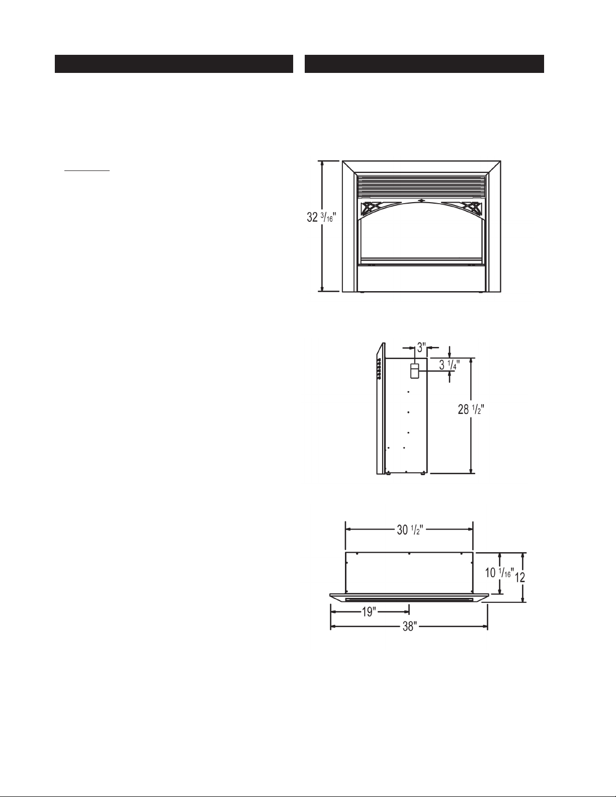
IMPORTANT INSTRUCTIONS LOCATING YOUR ELECTRIC FIREPLACE
1. READ ALL INSTRUCTIONS BEFORE USING THIS APPLI-
ANCE. THIS APPLIANCE IS HOT WHEN USED.
2. To avoid burns, DO NOT let bare skin touch hot surfaces.
The trim around the heat outlet becomes hot during fireplace operation. Keep combustible material; such as furniture, pillows, bedding, paper, clothes and draperies at
least 3 feet from the front of the unit.
CAUTION: Extreme caution is necessary when any fire-
3.
place is used by or near children or invalids, also whenever the heater is left operating and unattended.
4. Do not operate if the power cord or fireplace is damaged, or if the unit is dropped or damaged in any manner.
5. Under no circumstances should this fireplace be modified. Use it only as described in the manual. Any repairs to
the fireplace should be carried out by a qualified service
person.
6. Do not use outdoors.
7. Do not insert or allow foreign objects to enter any venti-
lation or exhaust openings as this may cause an electrical
short or fire. This could also damage the fireplace.
8. To prevent a possible fire, DO NOT block air intakes or
exhaust in any manner. DO NOT use on soft surfaces where
openings may become blocked.
9. This heater has hot and arcing or sparking parts inside.
DO NOT use in areas where gasoline, paint or flammable
liquids are used or stored. This fireplace SHOULD NOT be
used as a drying rack.
10. This fireplace is NOT intended for wood or other flam-
mable material to be burned inside of it.
11. Make sure the fireplace is unplugged before any cleaning or maintenance is performed on the heater.
12. Avoid the use of extension cords. The extension cord
may overheat and cause a fire.
13. Do not strike the glass on the fireplace.
14. Always unplug heater when not in use.
15. This heater is not intended for use in bathrooms, laun-
dry areas and similar indoor locations. Never locate heater
where it may fall into a bathtub or other water container.
16. Do not run cord under carpeting. Do not cover cord with
throw rugs, runners or similar coverings. Arrange cord away
from traffic area and where it will not be tripped over.
17. To disconnect heater, turn controls to off, then remove
the plug from the outlet.
18. Use this heater only as described in this manual. Any
other use not recommended by the manufacturer may
cause fire, electric shock or injury to persons.
Your new fireplace may be installed into an existing
masonary or zero clearance fireplace. It may also be installed using a prefabricated cabinet available from your
dealer or may be built into a wall. For the best effect, install
the fireplace out of direct sunlight.
SAVE THESE INSTRUCTIONS.
19.
W415-0330 / B / 03.25.04
Page 5

OPERATION
This fireplace is supplied with a infrared remote control.
This remote control operates with an arc of 50º and has
to be pointed at the infrared eye for it to work. (See fig. 1)
REMOTE CONTROL INITIALIZATION
This procedure is required every time the power is turned
off, or lost to the unit.
1. Turn on the power button of the hand held remote control. If there is no beep, access the front control panel.
2. To access the control panel, open the louvres with the
louvre tabs.
3. Make sure that the main power switch 1 of the front con-
trol panel is turned on.
4. Repeat step #1.
USAGE OF THE REMOTE CONTROL
A - Main power on/off : Activates the power to
the firelace from the remote control.
B - Fire Log Accent Light: To illuminate
the fireplace.(Can be used as a Nite Lite)
C - Flame effect and speed: 1,2,3,4, off.
D - Fan/Heater on/off: Turns the fan
and heater on and off.
E - Sound (optional)
C
D
MANUAL CONTROLS
By opening the top louvres with the louvre tabs you can
access the manual controls for the fireplace.
1. Power - activates power to the fireplace. Must be on for
the fireplace to work.
2. Manual Control - activates buttons 3, 4 & 5.
3. Fire Log Accent Light - switches the light on and off that
illuminates the fireplace. (Can be used as a Nite Lite).
4. Flame Effect and Speed - switches the flame on. Re-
peated pressing of the switch cycles the flame through
speeds 1 to 4 and off.
5. Fan / Heater - turns the fan and heater on and off.
6. Thermostat - Controls the temperature of the area.
To increase the temperature, turn the dial clockwise.
Note
The heater may emit a slight, harmlessThe heater may emit a slight, harmless
The heater may emit a slight, harmless
The heater may emit a slight, harmlessThe heater may emit a slight, harmless
odour when first used. This odour is aodour when first used. This odour is a
odour when first used. This odour is a
odour when first used. This odour is aodour when first used. This odour is a
normal condition caused by initial heat-normal condition caused by initial heat-
normal condition caused by initial heat-
normal condition caused by initial heat-normal condition caused by initial heat-
B
ing ofing of
E
internal hea internal hea
ing of
internal hea
ing ofing of
internal hea internal hea
terter
, any odour is normally the r, any odour is normally the r
ter
, any odour is normally the r
terter
, any odour is normally the r, any odour is normally the r
of household dust settling on theof household dust settling on the
of household dust settling on the
of household dust settling on theof household dust settling on the
heater element.heater element.
heater element.
heater element.heater element.
ter parter par
ter par
ter parter par
tsts
ts
tsts
. T. T
. T
. T. T
herher
her
herher
eaf-eaf-
eaf-
eaf-eaf-
esultesult
esult
esultesult
5
Batteries NOT included.Batteries NOT included.
Batteries NOT included.
Batteries NOT included.Batteries NOT included.
Two AA batteries required.Two AA batteries required.
Two AA batteries required.
Two AA batteries required.Two AA batteries required.
6
Manual Controls
MAINTENANCE
BULB REPLACEMENT
If you notice the flame look is darker on one side of the
fireplace, check the light bulbs to ensure that one has not
burned out.
Bulb must be replaced with a MAX 60 watt incandescent
clear light bulb.
1. Replace the bulb, turn the circuit breaker off or unplug
the appliance.
2. Remove the front facia.
3. Detach the light access panel by removing the four
screws.
4. Replace the burned out light bulb using a new 60 watt
clear incandescent bulb.
A
12345
5. Replace access panel and front facia.
6. Turn on the power or plug the appliance back in.
7. Turn on the main power and test.
FIGURE 1
Infrared Eye
Light Access Panel
W415-0330 / B / 03.25.04
Page 6

6
FINISHING
MANTEL
Depending on the width of the mantel, it may be installed
higher or lower from the top of the louvre opening. See
drawing and chart below for proper installation height of
your combustible mantel piece. Non-combustible mantels
may be installed at any height above the appliance opening.
When using paint or lacquer to finish theWhen using paint or lacquer to finish the
When using paint or lacquer to finish the
When using paint or lacquer to finish theWhen using paint or lacquer to finish the
mantel, such paint or lacquer must be heatmantel, such paint or lacquer must be heat
mantel, such paint or lacquer must be heat
mantel, such paint or lacquer must be heatmantel, such paint or lacquer must be heat
resistant to prevent discolouration.resistant to prevent discolouration.
resistant to prevent discolouration.
resistant to prevent discolouration.resistant to prevent discolouration.
1. Choose fireplace location.
2. Place fireplace in position.
3. Frame in fireplace with header across the top. It is im-
portant to allow for the finished facing materials when setting the depth of the frame.
4. Remove the two screws
from the sides of the fireplace and attach the nailing tabs with the screws.
5. To determine the final
location of the nailing tab,
you must first determine
the thickness of your fin-
ishing material (i.e.
drywall) This will determine the dimension from the control panel front edge to the nailing tab. Secure with a sheet
metal screw supplied.
6. Attach the nailing tabs to the frame.
Corner Installation
CLEARANCE TO COMBUSTIBLES
Sides.........................0 inches
Sides................. 0 mm / 0 inches
Back..........................0 inches
Sides................. 0 mm / 0 inches
Floor...........................0 inches
Floor................. 0 mm / 0 inches
Top............................ 0 inches
Top 0 mm / 0 inches
FRAMING AND FINISHING
Nailing
Tab
Installation
Sheet
Metal
Set the control panel front
edge flush with the finished
W415-0330 / B / 03.25.04
wall surface.
Screw
Top View
Front View
Note: In order to avoid the possibility of exposed insulation
or vapour barrier coming in contact with the
fireplace body, it is recommended that the walls of the
fireplace enclosure be “finished” (ie: drywall/sheetrock), as
you would finish any other outside wall of a home. This will
ensure that clearance to combustibles is maintained within
the cavity.
Page 7

HEARTH
A A
hearth is NOT necessaryhearth is NOT necessary
A
hearth is NOT necessary
A A
hearth is NOT necessaryhearth is NOT necessary
thetic purthetic pur
thetic pur
thetic purthetic pur
The finished height of the hearth must be accounted forThe finished height of the hearth must be accounted for
The finished height of the hearth must be accounted for
The finished height of the hearth must be accounted forThe finished height of the hearth must be accounted for
when framing in the fireplace to ensure that there is 3/8"when framing in the fireplace to ensure that there is 3/8"
when framing in the fireplace to ensure that there is 3/8"
when framing in the fireplace to ensure that there is 3/8"when framing in the fireplace to ensure that there is 3/8"
air space under the fair space under the f
air space under the f
air space under the fair space under the f
posesposes
poses
posesposes
..
.
..
but is recommended for aes-but is recommended for aes-
but is recommended for aes-
but is recommended for aes-but is recommended for aes-
irir
ee
placeplace
e
place
ee
placeplace
..
.
..
ir
irir
COLD CLIMATE INSTALLATION
WARNING:WARNING:
WARNING:
WARNING:WARNING:
hind the fireplace, when the fireplace is being installedhind the fireplace, when the fireplace is being installed
hind the fireplace, when the fireplace is being installed
hind the fireplace, when the fireplace is being installedhind the fireplace, when the fireplace is being installed
on an outside won an outside w
on an outside w
on an outside won an outside w
It is MANDIt is MAND
It is MAND
It is MANDIt is MAND
all or call or c
all or c
all or call or c
AA
TT
A
T
AA
TT
OROR
OR
OROR
hasehase
hase
hasehase
Y to haY to ha
Y to ha
Y to haY to ha
..
.
..
vv
e an insulae an insula
v
e an insula
vv
e an insulae an insula
ted wted w
ted w
ted wted w
all be-all be-
all be-
all be-all be-
LOG INSTALLATION
LOG BASE
7
#2
#1
D
3. The bottom end of log #2 is pressed against the inner
right side of the chamber. The underside branch of log #2
fits under the top end of log #1 to achieve the final position.
GLASS REPLACEMENT
A
#1
B
1. Position log #1 as shown, so that the bottom end is
pressed against the left inner side of the chamber. The log
base is molded to cradle the underside of log #1, allowing
it to rest diagonally, as shown.
#2
Slot for glass Slot for glass
Insert the glass into the slots located at the sides of the
viewing area. Slide the glass down the front of the unit until
it rests against the bottom lip of the viewing area.
C
2. For correct positoning of log #2, the top end of log #1
must be lifted up off the base, as shown.
W415-0330 / B / 03.25.04
Page 8

8
TRIM INSTALLATION
NOTE: Bending the tabs may be
required in order to achieve
correct alignment with the slots,
as shown.
1. Insert the top clips on the
back of the trim into the
slots in the top of the viewing area on the appliance,
as shown.
2. The lower clips, located
underneath the viewing
area of the appliance, fit
over the slots on the bottom window ledge of the
trim, as shown. The trim is
secure when you hear the
bottom clips click into
place.
LOUVRES
OPENING AND CLOSING CHAIN
TAB
W415-0330 / B / 03.25.04
During operation of the
appliance, the louvres
may become hot.
The louves must be
opened and closed using
the tabs located on the
ends of the second louvre from the top, as
shown.
The securing chains on
the louvres must be attached during operation.
Should the chains be removed, re-install by placing one end into the large
hole in the brackets
shown and snap down
into the smaller hole.
Page 9

ELECTRICAL CONNECTION
9
This fireplace requires a 15 amp, 120 volt and 60 hz
circuit that is grounded to the electrical socket. The fireplace should be on its own circuit. If there are other
appliances on the same circuit, this may cause the circuit breaker or fuse to blow when the fireplace heater is
in operation.
The unit comes with a 6' electrical cord, exiting the top
right side. Plan your installation to avoid the use of an
extension cord. If you require an extension cord, it must
be at least 16 awg wire and be rated for 2025 watts.
Electrical outlet wires must comply with local building
codes to reduce the risk of fire, electrical shock and
injury.
Do NOT use the fireplace if any part has been under
water.
Call a qualified service technician IMMEDIATELY to have
the fireplace inspected for damage to the electrical circuit.
HARD WIRING CONNECTION
If it is necessary to hard wire this fireplace, a qualifiedIf it is necessary to hard wire this fireplace, a qualified
If it is necessary to hard wire this fireplace, a qualified
If it is necessary to hard wire this fireplace, a qualifiedIf it is necessary to hard wire this fireplace, a qualified
electrician may remove the cord connection, and wireelectrician may remove the cord connection, and wire
electrician may remove the cord connection, and wire
electrician may remove the cord connection, and wireelectrician may remove the cord connection, and wire
this unit directly to the house hold wiring.this unit directly to the house hold wiring.
this unit directly to the house hold wiring.
this unit directly to the house hold wiring.this unit directly to the house hold wiring.
Permanently framing the fireplace with an enclosure, requires the fireplace to be hardwired.
This fireplace must be electrically connected and grounded
in accordance with local codes. In the absence of local
codes, use the current CSA C22.1 CANADIAN ELECTRICAL CODE in Canada or the ANSI/NFP A 70-1996 NA TIONAL
ELECTRICAL CODE in the United States.
ELECTRICAL DIAGRAM LEGEND
1.1.
Power (Rocker Switch)Power (Rocker Switch)
1.
Power (Rocker Switch)
1.1.
Power (Rocker Switch)Power (Rocker Switch)
2.2.
Manual ControlManual Control
2.
Manual Control
2.2.
Manual ControlManual Control
(moment switch)(moment switch)
(moment switch)
(moment switch)(moment switch)
3.3.
Fire Log Accent Light (moment switch)Fire Log Accent Light (moment switch)
3.
Fire Log Accent Light (moment switch)
3.3.
Fire Log Accent Light (moment switch)Fire Log Accent Light (moment switch)
4.4.
Flame Effect Switch (moment switch)Flame Effect Switch (moment switch)
4.
Flame Effect Switch (moment switch)
4.4.
Flame Effect Switch (moment switch)Flame Effect Switch (moment switch)
5.5.
Heater Switch (moment switch)Heater Switch (moment switch)
5.
Heater Switch (moment switch)
5.5.
Heater Switch (moment switch)Heater Switch (moment switch)
6.6.
Thermostat SwitchThermostat Switch
6.
Thermostat Switch
6.6.
Thermostat SwitchThermostat Switch
7.7.
Fan / Heater AssemblyFan / Heater Assembly
7.
Fan / Heater Assembly
7.7.
Fan / Heater AssemblyFan / Heater Assembly
8.8.
Jumper Wire BoardJumper Wire Board
8.
Jumper Wire Board
8.8.
Jumper Wire BoardJumper Wire Board
9.9.
Fire Log Accent (7 watts max.)Fire Log Accent (7 watts max.)
9.
Fire Log Accent (7 watts max.)
9.9.
Fire Log Accent (7 watts max.)Fire Log Accent (7 watts max.)
10.10.
Main Circuit BoardMain Circuit Board
10.
Main Circuit Board
10.10.
Main Circuit BoardMain Circuit Board
11.11.
DC Motor (flame effect)DC Motor (flame effect)
11.
DC Motor (flame effect)
11.11.
DC Motor (flame effect)DC Motor (flame effect)
12.12.
Main Power CordMain Power Cord
12.
Main Power Cord
12.12.
Main Power CordMain Power Cord
13.13.
Strain ReliefStrain Relief
13.
Strain Relief
13.13.
Strain ReliefStrain Relief
14.14.
Flame Effect Light (four light sockets-Flame Effect Light (four light sockets-
14.
Flame Effect Light (four light sockets-
14.14.
Flame Effect Light (four light sockets-Flame Effect Light (four light sockets-
15.15.
Infrared EyeInfrared Eye
15.
Infrared Eye
15.15.
Infrared EyeInfrared Eye
16.16.
Nylon Cable TieNylon Cable Tie
16.
Nylon Cable Tie
16.16.
Nylon Cable TieNylon Cable Tie
60 watts max60 watts max
60 watts max
60 watts max60 watts max
))
)
))
Electric Diagram
6
5
4
16
16
3
2
1
15
White / Green
12
13
10
8
White / Green
16
7
P10P8P6P4P2
P9 P7P5P3
P1
9
11
14
16
Black
White
16
16
W415-0330 / B / 03.25.04
Page 10

10
REPLACEMENTS
Contact your dealer for questions concerning prices and
availability of replacement parts. Normally all parts can be
ordered through your Napoleon dealer or distributor.
When ordering replacement parts always give the following information:
1. MODEL & SERIAL NUMBER OF FIREPLACE
2. INSTALLATION DATE OF FIREPLACE
3. PART NUMBER
4. DESCRIPTION OF PART
5. FINISH
FORFOR
FOR
FORFOR
THETHE
THE
THETHE
WARRANTYWARRANTY
WARRANTY
WARRANTYWARRANTY
ORIGINALORIGINAL
ORIGINAL
ORIGINALORIGINAL
REPLREPL
REPL
REPLREPL
INVOICEINVOICE
INVOICE
INVOICEINVOICE
AA
CEMENTCEMENT
A
CEMENT
AA
CEMENTCEMENT
WILLWILL
WILL
WILLWILL
CLAIMCLAIM
CLAIM
CLAIMCLAIM
PP
P
PP
BEBE
REQUIREDREQUIRED
BE
REQUIRED
BEBE
REQUIREDREQUIRED
..
.
..
ARAR
AR
ARAR
TSTS
TS
TSTS
, ,
,
, ,
AA
A
AA
PHOPHO
PHO
PHOPHO
TOTO
TO
TOTO
TT
OCOPYOCOPY
T
OCOPY
TT
OCOPYOCOPY
HONOURHONOUR
HONOUR
HONOURHONOUR
REPLACEMENT PARTS ACCESSORIES
# PART NO. DESCRIPTION
1* W300-0061 FRONT GLASS
2 W497-0001 PLASTIC DIFFUSER
3 W272-0001 RUBBER FOOT
4 W062-0016 FAN / HE ATER ASSEMBLY
5 W380-0013 THERMOSTAT KNOB
6 W385-0256 CONTROL PANEL LABEL A
7 W385-0258 CONTROL PANEL LABEL B
8 W387-0001 60 WA TT LIGHT BULB
9 W387-0002 7 WATT LIGHT BULB
10 W435-0004 FLAME EFFECT MOTOR
1 1 W660-0022 THERMOSTA T SWITCH
12 W660-0023 MAIN POWER SWITCH
13 W660-0024 MOMENT SWITCH
14 W660-0032 REMOTE CONTROL TRANSMITTER
15 W660-0033 RECEIVER
16 W010-0936 FLAME EFFECT ASSEMBLY
17* W045-0001 NYLON BEARING
18 GL-637 LOG SET
19 W135-0173 LOG #1
20 W135-0174 LOG #2
OFOF
OF
OFOF
THETHE
THE
THETHE
* IDENTIFIES ITEMS WHICH ARE NOT ILLUSTRATED. FOR
FURTHER
Use only accessories designed for and listed with the
EF38H model.
# PART NO. DESCRIPTION
21 EFF-K FRONT FACIA
22 CDV3-4L LOUVRE OVERLAY - POLISHED BRASS
22 CDV3-24L LOUVRE OVERLAY - POLISHED BRASS
22 CDV3-4LSS LOUVRE OVERLAY - STAINLESS STEEL
22 CDV3-24LSS LOUVRE OVERLAY - STAINLESS STEEL
7
INFORMATION, CONTACT YOUR NAPOLEON
DEALER
.
11
2
W385-02566W385-0258
10
8
4
22
9
3
18
5
13
15
12
16
21
14
20
19
W415-0330 / B / 03.25.04
Page 11

TROUBLE SHOOTING GUIDE
SYMPTOM PROBLEM TEST SOLUTION
No Flame Light but - Light bulbs have burned out. - Remove access panel and change
everything else is - Light could be loose. light bulbs.
working properly. - Remove access panel and tighten light bulb.
Flame light, but no - Flame generator motor has burned out. - Consult your local dealer.
movement in the flame - Flame generator has come loose. - Remove the access panel and check to make
sure the flame generator is in the flame
generator bracket, and is secured to the
motor with the rubber tube.
Remote control - Dead batteries. - Make sure batteries are charged.
not working - No power to the unit. - Make sure main power is on.
- Power turned off. - Turn on manual power switch.
Heater works but - Fan on heater is not working. - Consult your local dealer.
there is no air flow. - Air inlet is blocked. - Check that there is nothing blocking the air
inlets at either side near the bottom of the
fireplace.
Fan works but there is - Heater is not working. - Consult your local dealer.
no heat.
11
Fireplace will not - Breaker or fuse has blown. - Check main power switch is turned on.
turn on. - Fuse on circuit board may be blown - Consult your local dealer.
or loose.
Heater does not turn off. - Thermostat is set to high. - Turn thermostat counter-clockwise.
- Thermostat may be faulty. - Consult your local dealer.
Excessive noise coming - Dirt build up on fan bearing. - Consult your local dealer.
from the top of the unit. - Defective blower. - Vacuum the top control compartment.
Odour - Dust has settled on the - Run heater until odour ceases
heater element. (approx. 1/2 hr)
- Consult your local dealer.
Heater cycling on - Air intlets blocked. - Check to make sure there is nothing blocking
and off the air inlets on the bottom of the unit.
- Should not be on high pile carpet that can
block air inlets.
The fireplace turns off - Fuse may be loose - Consult your local dealer
when moved or bumped. (Remove the 5 screws from the control panel
and check that the fuse is not blown or loose.)
W415-0330 / B / 03.25.04
Page 12

12
Wolf Steel Fireplace Service History
Service Performed Special ConcernsDealer Name
Name
Service Technician
This fireplace must be serviced annually depending on usage.
W415-0330 / B / 03.25.04
Date
 Loading...