

Page 1
INSTALLER: LEAVE THIS MANUAL WITH THE APPLIANCE.
CONSUMER: RETAIN THIS MANUAL FOR FUTURE REFERENCE.
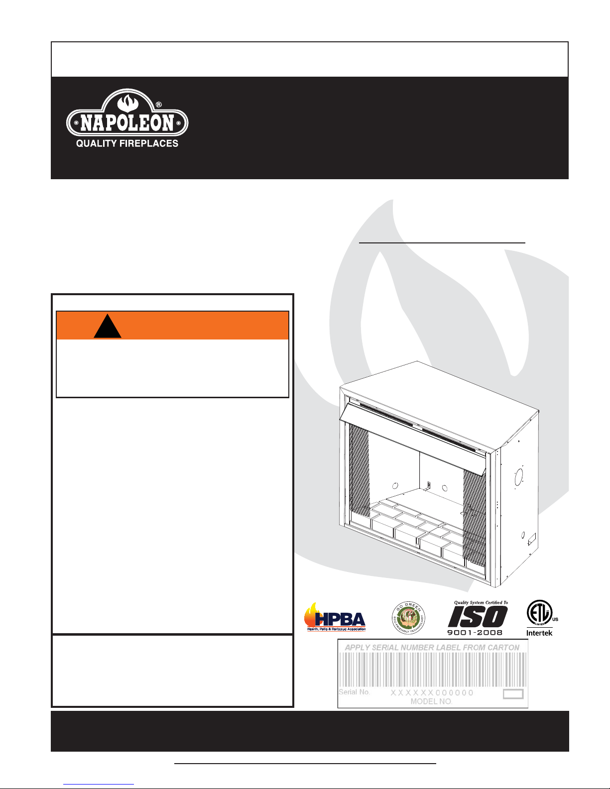
INSTALLATION AND
OPERATING INSTRUCTIONS
CONFORMS TO THE STANDARD ANSI Z21.91 VENTLESS FIREBOX ENCLOSURES FOR UNVENTED ROOM HEATERS
ZCVF36
ZCVF42
CERTIFIED FOR THE UNITED STATES USING ANSI METHODS.
1
SAFETY INFORMATION
!
WARNING
If the information in these instructions are
not followed exactly, a fi re or explosion
may result causing property damage,
personal injury or loss of life.
- Do not store or use gasoline or other fl ammable
vapors and liquids in the vicinity of this or any
other appliance.
- WHAT TO DO IF YOU SMELL GAS:
• Do not try to light any appliance.
• Do not touch any electrical switch; do not use
any phone in your building.
• Immediately call your gas supplier from a
neighbour’s phone. Follow the gas supplier’s
instructions.
• If you cannot reach your gas supplier, call the
fi re department.
- Installation and service must be performed by a
qualifi ed installer, service agency or the supplier.
- This is an unvented gas-fi red heater that
uses air (oxygen) from the room in which it is
installed. Provisions for adequate combustion
and ventilation air must be provided. Refer to
section “ COMBUSTION AND VENTILATION AIR
PROVISIONS”.
This appliance may be installed in an aftermarket,
permanently located, manufactured (mobile) home,
where not prohibited by local codes.
This appliance is only for use with the type of gas
indicated on the rating plate. This appliance is not
convertible for use with other gases.
ZERO CLEARANCE
VENTLESS FIREBOX
ENCLOSURE
Wolf Steel Ltd., 24 Napoleon Rd., Barrie, ON, L4M 0G8 Canada /
103 Miller Drive, Crittenden, Kentucky, USA, 41030
Phone (705)721-1212 • Fax (705)722-6031 • www.napoleonfi replaces.com • ask@napoleonproducts.com
$10.00
1.23A
W415-0527 / A / 04.14.11
Page 2
2
TABLE OF CONTENTS
1.0 INSTALLATION OVERVIEW 2
2.0 INTRODUCTION 3
2.1 DIMENSIONS 4
2.1.1 ZCVF36 4
2.1.2 ZCVF42 4
2.2 GAS INLET LOCATIONS 5
2.2.1 ZCVF36 5
2.2.2 ZCVF42 5
2.3 GENERAL INSTRUCTIONS 6
2.4 RATING PLATE INFORMATION 6
3.0 FRAMING 7
3.1 MINIMUM CLEARANCE TO COMBUSTIBLES 8
3.1.1 ZCVF36 8
3.1.2 ZCVF42 8
3.2 MINIMUM MANTEL CLEARANCES 9
3.3 NAILING TAB INSTALLATION 9
4.0 FINISHING 10
4.1 HOOD INSTALLATION 10
5.0 OPTIONAL BLOWER INSTALLATION 11
6.0 REPLACEMENTS 13
7.0 WARRANTY 14
8.0 SERVICE HISTORY 15
NOTE: Changes, other than editorial, are denoted by a vertical line in the margin
FOR USE ONLY WITH A ANSI Z21.11.2 LISTED GAS-FIRED UNVENTED ROOM HEATER NOT TO
EXCEED 40,000 BTU/H
FOLLOW THE INSTRUCTIONS, AND COMPLETE THE INSTALLATION OF THE UNVENTED ROOM
HEATER.
Carefully review the instructions supplied with the unvented room heater for the mimimun fi rebox
size requirement.
DO NOT INSTALL AN APPLIANCE IN THIS FIREBOX UNLESS THIS FIREBOX MEETS THE MINIMUM
DIMENSIONS REQUIRED FOR THE INSTALLATION.
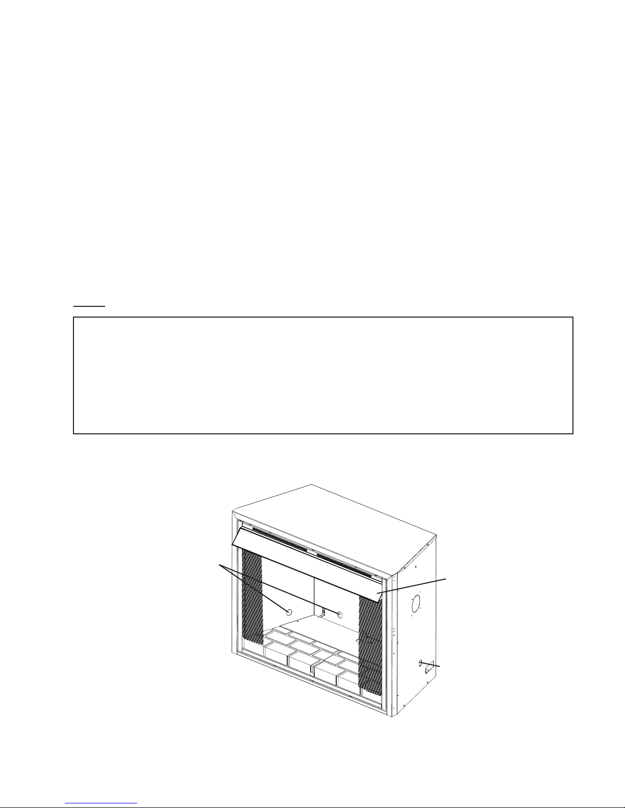
1.0 INSTALLATION OVERVIEW
Gas inlet, see “GAS INLET
LOCATIONS” section.
Hood, see “HOOD
INSTALLATION” section.
Gas inlet, see “GAS INLET
LOCATIONS” section.
W415-0527 / A / 04.14.11
Page 3

2.0 INTRODUCTION
• THIS APPLIANCE IS HOT WHEN OPERATED AND CAN CAUSE SEVERE BURNS IF CONTACTED.
• ANY CHANGES TO THIS APPLIANCE OR ITS CONTROLS CAN BE DANGEROUS AND IS PROHIBITED.
• Under no circumstances should this appliance be modifi ed.
• Do not operate appliance before reading and understanding operating instructions. Failure to operate
appliance according to operating instructions could cause fi re or injury.
• Risk of burns. The appliance should be turned off and cooled before servicing.
• Do not install damaged, incomplete or substitute components.
• Risk of cuts and abrasions. Wear protective gloves and safety glasses during installation. Sheet metal edges
may be sharp.
• Provide adequate ventilation and combustion air. Provide adequate accessibility clearance for servicing and
operating the appliance. Never obstruct the front opening of the appliance.
• If the appliance shuts off, do not re-light until you provide fresh air. If appliance keeps shutting off, have it
serviced. Keep burner and control compartment clean.
• Do not burn wood or other materials in this appliance.
• Children and adults should be alerted to the hazards of high surface temperature and should stay away to
avoid burns or clothing ignition.
• Young children should be carefully supervised when they are in the same room as the appliance. Toddlers,
young children and others may be susceptible to accidental contact burns. A physical barrier is recommended
if there are at risk individuals in the house. To restrict access to an appliance, install an adjustable safety gate
to keep toddlers, young children and other at risk individuals out of the room and away from hot surfaces.
• Due to high temperatures, the appliance should be located out of traffi c and away from furniture and
draperies.
• Ensure you have incorporated adequate safety measures to protect infants/toddlers from touching hot
surfaces.
• Clothing or other fl ammable material should not be placed on or near the appliance.
• Check with your local hearth specialty dealer for safety screens and hearth guards to protect children from
hot surfaces. These screens and guards must be fastened to the fl oor.
• Any safety screen or guard removed for servicing must be replaced prior to operating the appliance.
• It is imperative that the control compartments, burners and circulating blower and its passageway in the
appliance are kept clean. The appliance should be inspected before use and at least annually by a qualifi ed
service person. More frequent cleaning may be required due to excessive lint from carpeting, bedding
material, etc. The appliance area must be kept clear and free from combustible materials, gasoline and other
fl ammable vapours and liquids.
• Furniture or other objects must be kept a minimum of 4 feet away from the front of the appliance.
• Do not use this appliance if any part has been under water. Immediately call a qualifi ed service technician
to inspect the appliance and to replace any part of the control system and any gas control which has been
under water.
• Do not allow fans to blow directly into the appliance. Avoid any drafts that alter burner fl ame patterns.
• Do not use a blower insert, heat exchanger insert or other accessory not approved for use with this appliance.
• Carbon or soot should not occur in a vent free appliance as it can distribute into the living area of your home.
If you notice any signs of carbon or soot, immediately turn off your appliance and arrange to have it serviced
by a qualifi ed technician before operating it again.
• Keep the packaging material out of reach of children and dispose of the material in a safe manner. As with all
plastic bags, these are not toys and should be kept away from children and infants.
• As with any combustion appliance, we recommend having your appliance regularly inspected and serviced as
well as having a Carbon Monoxide Detector installed in the same area to defend you and your family against
Carbon Monoxide.
• If equipped, the screen must be in place (closed) when the appliance is in operation.
• Ensure clearances to combustibles are maintained when building a mantel or shelves above the appliance.
Elevated temperatures on the wall or in the air above the appliance can cause melting, discolouration or
damage to decorations, a T.V. or other electronic components.
!
WARNING
3
3.4B
W415-0527 / A / 04.14.11
Page 4
4
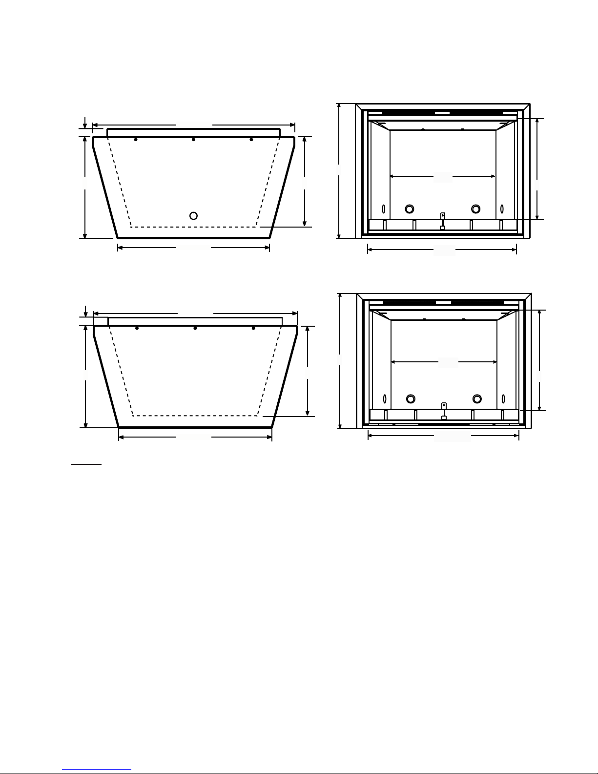
2.1 DIMENSIONS
2.1.1 ZCVF36
1 3/4”
42”
21 1/8”
2.1.2 ZCVF42
1 3/4”
21 1/8”
31 7/8”
46 5/8”
36 3/8”
19”
19”
32 1/2”
35 1/2”
25”
36”
30 ”
40 1/2 ”
23”
26”
NOTE: Dashed lines represent the shape of the fi rebox walls and back
W415-0527 / A / 04.14.11
Page 5

2.2 GAS INLET LOCATIONS
There are fi ve gas inlet locations on the ventless fi rebox enclosure. One on each side of the unit, two at the rear,
and one on the bottom. Using the following illustrations identify the preferred inlet and remove corresponding
knock out.
2.2.1 ZCVF36
5
16 3/8”
7”
2.2.2 ZCVF42
7”
16 3/8”
13”
7”
7”
13 1/4”
13 1/4”
21”
16 3/8”
23 3/8”
W415-0527 / A / 04.14.11
Page 6

6
ANCENCE
,,
THAHA
NN
PPLIPPLI
CA
EE
..
NUNVEN
TT
EHE
AA
TERSTERS
TIOTIOSE
V
TT
MINFORATION
AMANUA
A
TION,ON,
UCONSU
T
AA
AA
YY
EFLAMMABLE
VV
APA
ANYAATIVETIV
TOM
SIDESIDE
4ZCVF4
RINSINS
TT
ALLAL
A
TIONSNS
22
EINSIDE
LWALL
OFOF
CEFIREPLACERO
TT
GED
2.3 GENERAL INSTRUCTIONS
THE INSTALLATION MUST CONFORM WITH LOCAL CODES OR, IN THE ABSENCE OF LOCAL CODES
WITH THE NATIONAL FUEL GAS CODE, ANSI Z223.1 / NFPA 54 AND TO THE NATIONAL ELECTRICAL
CODE, ANSI / NFPA 70.
Use only accessories designed for and listed with your specifi c fi rebox.
Not designed for use with a glass door. Screen must be closed when appliance is in operation.
2.4 RATING PLATE INFORMATION
CERTIFIED UNDER: ANSI Z21.91-2007 VENTLESS FIREBOX ENCLOSURES FOR GAS-FIRED UNVENTED DECORA TIVE ROOM HEATERS
WARNING:FOR USE WITH LISTED ANSI Z21.1 1.2 UNVENTED GAS-FIRED ROOM HEA TERS NOT TO EXCEED 40,000
BTU/HR. IMPROPER INSTALLATION, ADJUSTMENT, ALTERATION, SERVICE OR MAINTENANCE CAN CAUSE
INJURY OR PROPERTY DAMAGE. REFER TO THE OWNER’S INFORMATION MANUAL PROVIDED WITH THIS
9700539 (WSL)
4001657 (NGZ)
4001658 (NAC)
4001659 (WUSA)
WARNING:DO NOT ADD ANY MATERIAL TO THE APPLIANCE,
WHICH WILL COME IN CONTACT WITH THE FLAMES, OTHER THAN
THAT SUPPLIED BY THE MANUF ACTURER WITH THE APPLIANCE.
FOR INSTALLATION IN A SOLID-FUEL BURNING FIREPLACE OR
VENTLESS FIREBOX ENCLOSURES FOR GAS FIRED UNVENTED
DECORATIVE ROOM HEA TERS.
MINIMUM CLEARANCE TO
COMBUSTIBLES
TOP 0
SIDES 0
BACK 0
MANTEL 4"
APPLIANCE. FOR ASSIST ANCE OR ADDITIONAL INFORMA TION, CONSUL T A QUALIFIED INSTALLER, SER VICE
AGENCY OR THE GAS SUPPLIER.
ZCVF36
AN
OR
NVE
4” TO MANTEL
0” TOP
0” BACK
0” SIDE
0” BOTTOM
CLEARANCES FOR GAS
LOG INSTALLATIONS
0” SIDE
N
FRONT
ED
EDGE
INSID
WAL
INSIDE WALL
IREPLA
OF FIREPLACE
FOR
2”
ZCVF42
ZCVF
FOR YOUR SAFETY:DO NOT ST ORE OR USE GASOLINE OR OTHER
FORYO
R
FLAMMABLE VAPOURS AND LIQUIDS IN THE VICINITY OF THIS
FLAMMABL
OR ANY OTHER APPLIANCE.
OR
ANY
ELECTRICAL RATING: 115V 0.82AMP, 60HZ
OPTIONAL FAN KIT: GZ550-KT
WOLF STEEL LTD.
24 NAPOLEON ROAD. BARRIE, ONTARIO L4M 0G8 CANADA
SERIAL NUMBER: ZCVF
INFOR
CONS
ROOMH
I
ORIN
ANU
W385-0318 / E
For rating plate location, see “INSTALLATION OVERVIEW” section.
This illustration is for reference only. Refer to the rating plate on the appliance for accurate information.
W415-0527 / A / 04.14.11
Page 7

3.0 FRAMING
IN ORDER TO AVOID THE POSSIBILITY OF EXPOSED INSULATION OR VAPOUR BARRIER COMING
IN CONTACT WITH THE APPLIANCE BODY, IT IS RECOMMENDED THAT THE WALLS OF THE
APPLIANCE ENCLOSURE BE “FINISHED” (IE: DRYWALL / SHEETROCK), AS YOU WOULD FINISH
ANY OTHER OUTSIDE WALL OF A HOME. THIS WILL ENSURE THAT CLEARANCE TO
DO NOT NOTCH THE FRAMING AROUND THE APPLIANCE STAND-OFFS. FAILURE TO MAINTAIN
AIR SPACE CLEARANCE MAY CAUSE OVER HEATING AND FIRE. PREVENT CONTACT WITH
SAGGING OR LOOSE INSULATION OR FRAMING AND OTHER COMBUSTIBLE MATERIALS. BLOCK
OPENING INTO THE CHASE TO PREVENT ENTRY OF BLOWN-IN INSULATION. MAKE SURE
WHEN CONSTRUCTING THE ENCLOSURE ALLOW FOR FINISHING MATERIAL THICKNESS TO
MAINTAIN CLEARANCES. FRAMING OR FINISHING MATERIAL CLOSER THAN THE MINIMUMS
LISTED MUST BE CONSTRUCTED ENTIRELY OF NON-COMBUSTIBLE MATERIALS. MATERIALS
CONSISTING ENTIRELY OF STEEL, IRON, BRICK, TILE, CONCRETE, SLATE, GLASS OR PLASTERS,
OR ANY COMBINATION THEREOF ARE SUITABLE. MATERIALS THAT ARE REPORTED AS PASSING
ASTM E 136, STANDARD TEST METHOD FOR BEHAVIOUR OF MATERIALS IN A VERTICAL TUBE
FURNACE AT 750°C AND UL763 SHALL BE CONSIDERED NON-COMBUSTIBLE MATERIALS.
!
WARNING
RISK OF FIRE!
COMBUSTIBLES IS MAINTAINED WITHIN THE CAVITY.
INSULATION AND OTHER MATERIALS ARE SECURED.
7
MINIMUM CLEARANCE TO COMBUSTIBLES MUST BE MAINTAINED OR A SERIOUS FIRE HAZARD
COULD RESULT.
THE APPLIANCE REQUIRES A MINIMUM ENCLOSURE HEIGHT. MEASURE FROM THE APPLIANCE
BASE.
IF STEEL STUD FRAMING KITS WITH CEMENT BOARD ARE PROVIDED, THEY MUST BE
INSTALLED.
71.1
ZCVF36
32 3/4"
ZCVF42
35 3/4"
21 1/4"
42 1/2”
21 1/4"
47 1/8”
W415-0527 / A / 04.14.11
Page 8

8
3.1 MINIMUM CLEARANCE TO COMBUSTIBLES
Note: In order to avoid the possibility of exposed insulation or vapour barrier coming in contact with the ventless
fi rebox enclosure body, it is recommended that the walls of the ventless fi rebox enclosure enclosure be “fi nished”
(ie: drywall/sheetrock), as you would fi nish any other outside wall of a home. This will ensure that clearance to
combustibles is maintained within the cavity.
When roughing in the ventless fi rebox enclosure, raise the ventless fi rebox enclosure to accommodate for the
thickness of the fi nished fl oor materials, i.e. tile, carpeting, hard wood.
Objects placed in front of the ventless fi rebox enclosure should be kept a minimum of 4 feet away from the front
face.
Minimum clearance to combustible construction from appliance:
sides, back, bottom and top of the unit 0 inch
recessed depth 21 1/4 inches
3.1.1 ZCVF36
OUTSIDE
CHASE
21 1/4"
21 1/4”
3.1.2 ZCVF42
OUTSIDE
CHASE
42 1/2"
42 1/2”
47 1/8"
INSIDE
CHASE
6"
21 1/4"
52 3/8”
42 1/2”
74 1/8”
55 5/8”
47 1/8”
21 1/4”
47 1/8”
W415-0527 / A / 04.14.11
INSIDE
CHASE
6"
78 5/8”
Page 9

3.2 MINIMUM MANTEL CLEARANCES
RISK OF FIRE, MAINTAIN ALL SPECIFIED AIR SPACE CLEARANCES TO COMBUSTIBLES. FAILURE
TO COMPLY WITH THESE INSTRUCTIONS MAY CAUSE A FIRE OR CAUSE THE APPLIANCE TO
OVERHEAT. ENSURE ALL CLEARANCES (I.E. BACK, SIDE, TOP, VENT, MANTEL, FRONT, ETC.) ARE
CLEARLY MAINTAINED.
WHEN USING PAINT OR LACQUER TO FINISH THE MANTEL, THE PAINT OR LACQUER MUST BE
HEAT RESISTANT TO PREVENT DISCOLOURATION.
Combustible materials may be installed fl ush with the front of the ventless fi rebox enclosure but must not cover
any of the black face-areas of the ventless fi rebox enclosure. Non-combustible material (brick, stone or ceramic
tile) may protrude in these areas.
Combustible mantel clearance can vary according to the mantel depth. Use the graph to help evaluate the
clearance needed.
!
WARNING
9
73.1
7
(
-
6
%
!
5
)
.
4
'
4
(
%
4
,
MANTEL WIDTH
4
3.3 NAILING TAB INSTALLATION
A. Attach the nailing tabs to the corner posts using the 2 sheet metal screws sup-
plied. Secure through the centre of the top and bottom slots in the nailing tab and
then through the existing holes in the corner posts. If there are no existing holes,
follow these instructions:
B. To determine the fi nal location of the nailing tab you must fi rst determine the
thickness of your fi nishing material (i.e. drywall). This will determine the dimen-
sion from the front edge of the corner post to the nailing tab. Once the nailing tab
is in the desired location, drill through the centre hole of the nailing tab. Secure
with a sheet metal screw*.
567
7"
7" MANTEL
6" MANTEL
4" MANTEL
6"
4"
TOP OF UNIT
COMBUSTIBLE
MATERIALS
STUD
NAILING TAB
* Additional set screws may be installed.
55.1A
W415-0527 / A / 04.14.11
Page 10

10
4.0 FINISHING
NEVER OBSTRUCT THE FRONT OPENING OF THE APPLIANCE.
THE FRONT OF THE APPLIANCE MUST BE FINISHED WITH ANY NON-COMBUSTIBLE MATERIALS
SUCH AS BRICK, MARBLE, GRANITE, ETC., PROVIDED THAT THESE MATERIALS DO NOT GO
BELOW THE SPECIFIED DIMENSION AS ILLUSTRATED. AS AN ALTERNATIVE, YOU CAN FINISH THE
APPLIANCE WITH DRYWALL, SEE ILLUSTRATIONS TO FOLLOW.
FACING AND/OR FINISHING MATERIAL MUST NEVER OVERHANG INTO THE APPLIANCE OPENING.
4.1 HOOD INSTALLATION
APPLIANCE SCREENS MUST BE CLOSED WHILE THE APPLIANCE IS IN OPERATION.
THE APPLIANCE MUST NOT BE USED WHEN THE HOOD IS REMOVED.
THE HOOD MUST NOT BE MODIFIED OR REPLACED WITH A HOOD THAT MAY BE PROVIDED WITH
!
WARNING
RISK OF FIRE!
!
WARNING
THE UNVENTED DECORATIVE ROOM HEATER.
72.2
Note: Remove the hood from the back side of the
carton by cutting the cable ties holding it in place.
A. Slide the edge of the hood into place on the top
inside surface of the ventless fi rebox enclosure to
align with the three pre-drilled holes.
2
1
B. Screw the hood securely into place with the three
screws provided.
W415-0527 / A / 04.14.11
Page 11

5.0 OPTIONAL BLOWER INSTALLATION
!
WARNING
RISK OF FIRE AND ELECTRICAL SHOCK.
TURN OFF THE GAS AND ELECTRICAL POWER BEFORE SERVICING THIS APPLIANCE.
USE ONLY WOLF STEEL APPROVED OPTIONAL ACCESSORIES AND REPLACEMENT PARTS WITH
THIS APPLIANCE. USING NON-LISTED ACCESSORIES (BLOWERS, DOORS, LOUVRES, TRIMS, GAS
COMPONENTS, VENTING COMPONENTS, ETC.) COULD RESULT IN A SAFETY HAZARD AND WILL
VOID THE WARRANTY AND CERTIFICATION.
ENSURE THAT THE FAN’S POWER CORD IS NOT IN CONTACT WITH ANY SURFACE OF THE
APPLIANCE TO PREVENT ELECTRICAL SHOCK OR FIRE DAMAGE. DO NOT RUN THE POWER
CORD BENEATH THE APPLIANCE.
THE WIRE HARNESS PROVIDED IN THE BLOWER KIT IS A UNIVERSAL HARNESS. WHEN
INSTALLED, ENSURE THAT ANY EXCESS WIRE IS CONTAINED, PREVENTING IT FROM MAKING
CONTACT WITH MOVING OR HOT OBJECTS.
INST ALLA TION T O BE DONE BY A QUALIFIED INSTALLER and must be electrically connected and grounded
in accordance with local codes. In the absence of local codes, use the current ANSI/NFPA 70 National Electrical
Code.
11
51.5
If the fi rebox was not previously equipped with a blower: route a grounded
2-wire, 60hz power cable through the junction plate cover. At this point it must
be strain relieved and insulated.
The three slots on the blower mounting bracket allow ease of adjustment when
attaching the blower. For a quiet running blower, do not allow the assembly to
sit on the fi rebox base. Slide the vibration reducing pad (A) into the clip (C) and
up against the threaded stud (B) at the other end. The blower must be able to be
positioned entirely onto the pad.
Tilt the blower onto its side. Slide it past the
controls and into the clip (C). Secure to the
threaded stud using the lock washer and wing
nut provided. Ensure that the blower does not
touch the fi rebox base or the fi rebox. Attach the
connectors from the black and red wires to the
blower.
The wire harness provided in this kit is a universal harness. When installed, ensure that any excess wire is
contained, preventing it from making contact with moving or hot objects. Because the blower is thermally
activated, when turned on, it will automatically start approximately 30 minutes after lighting the vent free room
heater and will run for approximately 30-45 after the vent free room heater has been turned off. Use of the fan
increases the output of heat.
Drywall dust will penetrate into the blower bearings causing irreparable damage. Care must be taken to prevent
drywall dust from coming into contact with the blower or its compartment. Any damage resulting from this
condition is not covered by the warranty policy.
B
A
ELONGATED
SLOTS
C
W415-0527 / A / 04.14.11
Page 12

12
* Note: In either application it is necessary to remove the variable speed switch from the wiring harness and install into an electrical switch box as per electrical codes.
WITH THERMAL SWITCH BRACKET
A. Remove the hearth pads and the
blower access cover.
B. Install the blower using the
optional blower installation
instructions.
C. Pull the black and white thermal
disc wires through the 7/8”
bushing in the blower access
cover.
D. Cut the white wire as close to the
connector as possible.
E. Cut the red wire as close to the
plug as possible.
2
1
6
3
4
F. Using a box connector, connect
supply wire through the junction
cover plate located on the right
side of the fi rebox enclosure.
G. Connect the red and white wires
to the power supply. Attach the
ground to the ground screw on
the junction plate cover.
1. Hearth Pads
2. Blower Access Cover
3. Thermal Switch Support Bracket
4. 7/8” Bushing
5. Junction Plate
6. Thermal Switch Bracket
G
R
BLOWER
5
O
W
E
R
C
S
D
N
U
H. Replace the blower access cover.
I. Attach the black & white wires to the back of the thermal
switch and install at the rear of the fi rebox using the
thermal switch support bracket as illustrated.
BLACK
RED
J. Replace the hearth pads.
WITHOUT THERMAL SWITCH BRACKET
A. Remove the hearth pads and blower access cover.
B. Install the blower using the optional blower installation
instructions.
C. Cut the red wire as close to the plug as possible.
D. Cut the black wire as close to the fl ag connection as
possible.
E. Using a box connector, connect supply wire though the
junction cover plate located on the right side of the fi rebox
enclosure.
F. Attach the ground to the ground screw on the junction
plate cover.
G. Replace the blower access cover plate and hearth pads.
WHITE
THERMAL DISC
*
VARIABLE
SPEED
SWITCH
BLOWER
BLACK
RED
WHITE
THERMAL DISC
*
VARIABLE
SPEED
SWITCH
W415-0527 / A / 04.14.11
Page 13

6.0 REPLACEMENTS
Contact your dealer or the factory for questions concerning prices and policies on replacement parts. Normally
all parts can be ordered through your Authorized dealer / distributor.
FOR WARRANTY REPLACEMENT PARTS, A PHOTOCOPY OF THE ORIGINAL INVOICE WILL BE
REQUIRED TO HONOUR THE CLAIM.
When ordering replacement parts always give the following information:
• Model & Serial Number of appliance
• Installation date of appliance
• Part number
• Description of part
• Finish
* IDENTIFIES ITEMS WHICH ARE NOT ILLUSTRATED. FOR
FURTHER INFORMA TION, CONTACT YOUR AUTHORIZED DEALER.
REF ZCVF36 ZCVF42 DESCRIPTION
1* W385-0334 W385-0334 NAPOLEON LOGO
2 W565-0084 W565-0085 CURTAIN MESH
3 W565-0056 W565-0057 CURTAIN ROD
4 W335-0044 W335-0045 HOOD
5* W500-0192 W500-0192 PANEL BRACKETS
6 W475-0400 W475-0399 HEARTH PAD (RIGHT)
7 W475-0386 W475-0382 HEARTH PAD (LEFT)
REF ZCVF36 ZCVF42 DESCRIPTION
8* 11 1KT 1 1 1KT OUTSIDE AIR KIT
9* 112KT 112KT ADAPTOR PLATE, OUTSIDE AIR KIT
10* GD810-KT GD809-KT BRICK PANELS (COBBLESTONE)
11 DKZC36SS DKZC42SS DECORATIVE DOOR
12 TBZC36K TBZC42K 3” BEVELLED TRIM (BLACK)
12 TBZC36SS TBZC42SS 3” BEVELLED TRIM (SATIN CHROME)
13 GZ550-1KT GZ550-1KT BLOWER KIT
14 W500-0033 W500-0033 WALL SWTICH MOUNTING PLATE
COMPONENTS
ACCESSORIES
13
!
WARNING
FAILURE TO POSITION THE PARTS
IN ACCORDANCE WITH THIS
MANUAL OR FAILURE TO USE ONLY
PARTS SPECIFICALLY APPROVED
WITH THIS APPLIANCE MAY
RESULT IN PROPERTY DAMAGE OR
PERSONAL INJURY.
41.1
12
4
11
3
2
7
13
6
W415-0527 / A / 04.14.11
Page 14

14
7.0 WARRANTY
NAPOLEON® products are manufactured under the strict Standard of the world recognized ISO 9001 : 2008 Quality Assurance
NAPOLEON® products are designed with superior components and materials assembled by trained craftsmen who take great
pride in their work. The burner and valve assembly are leak and test-fi red at a quality test station. The complete appliance is
again thoroughly inspected by a qualifi ed technician before packaging to ensure that you, the customer, receives the quality
NAPOLEON® GAS APPLIANCE PRESIDENT’S LIFETIME LIMITED WARRANTY
The following materials and workmanship in your new NAPOLEON® gas appliance are warranted against defects for as long as
you own the appliance. This covers: combustion chamber, heat exchanger, stainless steel burner, phazer™ logs and embers, rocks,
ceramic glass (thermal breakage only), gold plated parts against tarnishing, porcelainized enameled components and aluminum
extrusion trims.*
Electrical (110V and millivolt) components and wearable parts such as blowers, gas valves, thermal switch, switches, wiring, remote
controls, ignitor, gasketing, and pilot assembly are covered and NAPOLEON® will provide replacement parts free of charge during
the fi rst year of the limited warranty.*
Labour related to warranty repair is covered free of charge during the fi rst year. Repair work, however, requires the prior approval of
an authorized company offi cial. Labour costs to the account of NAPOLEON® are based on a predetermined rate schedule and any
repair work must be done through an authorized NAPOLEON® dealer.
* Construction of models vary. Warranty applies only to components included with your specifi c appliance.
Certifi cate.
product that you expect from NAPOLEON®.
CONDITIONS AND LIMITATIONS
NAPOLEON® warrants its products against manufacturing defects to the original purchaser only. Registering your warranty is not necessary. Simply
provide your proof of purchase along with the model and serial number to make a warranty claim. NAPOLEON® reserves the right to have its
representative inspect any product or part thereof prior to honouring any warranty claim. Provided that the purchase was made through an authorized
NAPOLEON® dealer your appliance is subject to the following conditions and limitations:
Warranty coverage begins on the date of original installation.
This factory warranty is non-transferable and may not be extended whatsoever by any of our representatives.
The gas appliance must be installed by a licensed, authorized service technician or contractor. Installation must be done in accordance with the installation
instructions included with the product and all local and national building and fi re codes.
This limited warranty does not cover damages caused by misuse, lack of maintenance, accident, alterations, abuse or neglect and parts installed from
other manufacturers will nullify this warranty.
This limited warranty further does not cover any scratches, dents, corrosion or discoloring caused by excessive heat, abrasive and chemical cleaners nor
chipping on porcelain enamel parts, mechanical breakage of PHAZER™ logs and embers.
This warranty extends to the repair or replacement of warranted parts which are defective in material or workmanship provided that the product has been
operated in accordance with the operation instructions and under normal conditions.
After the fi rst year, with respect to this President’s Lifetime Limited Warranty, NAPOLEON® may, at its discretion, fully discharge all obligations with
respect to this warranty by refunding to the original warranted purchaser the wholesale price of any warranted but defective part(s).
NAPOLEON® will not be responsible for installation, labour or any other expenses related to the reinstallation of a warranted part and such expenses are
not covered by this warranty.
Notwithstanding any provisions contained in the President’s Lifetime Limited Warranty, NAPOLEON’S responsibility under this warranty is defi ned as
above and it shall not in any event extend to any incidental, consequential or indirect damages.
This warranty defi nes the obligations and liability of NAPOLEON® with respect to the NAPOLEON® gas appliance and any other warranties expressed or
implied with respect to this product, its components or accessories are excluded.
NAPOLEON® neither assumes, nor authorizes any third party to assume, on its behalf, any other liabilities with respect to the sale of this product.
NAPOLEON® will not be responsible for: over-fi ring, downdrafts, spillage caused by environmental conditions such as rooftops, buildings, nearby trees,
hills, mountains, inadequate vents or ventilation, excessive venting confi gurations, insuffi cient makeup air, or negative air pressures which may or may not
be caused by mechanical systems such as exhaust fans, furnaces, clothes dryers, etc.
Any damages to the appliance, combustion chamber, heat exchanger, plated trim or other components due to water, weather damage, long periods of
dampness, condensation, damaging chemicals or cleaners will not be the responsibility of NAPOLEON®.
All parts replaced under the President’s Limited Lifetime Warranty Policy are subject to a single claim.
During the fi rst 10 years NAPOLEON® will replace or repair the defective parts covered by the lifetime warranty at our discretion free of charge. From 10
years to life, NAPOLEON® will provide replacement parts at 50% of the current retail price.
All parts replaced under the warranty will be covered for a period of 90 days from the date of their installation.
The manufacturer may require that defective parts or products be returned or that digital pictures be provided to support the claim. Returned products are
to be shipped prepaid to the manufacturer for investigation. If a product is found to be defective, the manufacturer will repair or replace such defect.
Before shipping your appliance or defective components, your dealer must obtain an authorization number. Any merchandise shipped without
authorization will be refused and returned to sender.
Shipping costs are not covered under this warranty.
Additional service fees may apply if you are seeking warranty service from a dealer.
Warranty labour allowance is only for the replacement of the warranted part. Travel, diagnostic tests, shipping and other related charges are not covered
by this warranty.
ALL SPECIFICATIONS AND DESIGNS ARE SUBJECT TO CHANGE WITHOUT PRIOR NOTICE DUE TO ON-GOING PRODUCT
IMPROVEMENTS. NAPOLEON® IS A REGISTERED TRADEMARK OF WOLF STEEL LTD.
W415-0527 / A / 04.14.11
2.1B
Page 15

8.0 SERVICE HISTORY
15
43.1
W415-0527 / A / 04.14.11
Page 16

16
14.0 NOTES
W415-0527 / A / 04.14.11
44.1
 Loading...