

Page 1
INSTALLER: LEAVE THIS MANUAL WITH THE APPLIANCE.
CONSUMER: RETAIN THIS MANUAL FOR FUTURE REFERENCE.
NEVER LEAVE CHILDREN OR OTHER AT RISK INDIVIDUALS ALONE WITH THE APPLIANCE.
INSTALLATION AND
OPERATING INSTRUCTIONS
CERTIFIED UNDER CANADIAN AND AMERICAN NATIONAL STANDARDS: CSA 2.33, ANSI Z21.88 FOR VENTED GAS FIREPLACE HEATERS.
XIR3N / IR3N
CERTIFIED FOR CANADA AND UNITED STATES USING ANSI/CSA METHODS.
SAFETY INFORMATION
NATURAL GAS
XIR3P /IR3P
!
WARNING
If the information in these instructions
are not followed exactly, a fi re or
explosion may result causing property
damage, personal injury or loss of life.
PROPANE
1
- Do not store or use gasoline or other fl ammable
vapors and liquids in the vicinity of this or any
other appliance.
- WHAT TO DO IF YOU SMELL GAS:
• Do not try to light any appliance.
• Do not touch any electrical switch; do not use
any phone in your building.
• Immediately call your gas supplier from a
neighbour’s phone. Follow the gas supplier’s
instructions.
• If you cannot reach your gas supplier, call the
fi re department.
- Installation and service must be performed by a
qualifi ed installer, service agency or the supplier.
This appliance may be installed in an aftermarket,
permanently located, manufactured home (USA
only) or mobile home, where not prohibited by
local codes.
This appliance is only for use with the type of gas
indicated on the rating plate. This appliance is
not convertible for use with other gases, unless a
certifi ed kit is used.
!
WARNING
HOT GLASS WILL CAUSE
BURNS.
DO NOT TOUCH GLASS UNTIL
COOLED.
NEVER ALLOW CHILDREN TO
TOUCH GLASS.
Wolf Steel Ltd., 24 Napoleon Rd., Barrie, ON, L4M 0G8 Canada /
103 Miller Drive, Crittenden, Kentucky, USA, 41030
Phone (705)721-1212 • Fax (705)722-6031 • www.napoleonfi replaces.com • ask@napoleonproducts.com
$10.00
1.36A
CERTIFIED
W415-1033 / A / 10.12.11
Page 2

2
TABLE OF CONTENTS
1.0 INSTALLATION OVERVIEW 3
2.0 INTRODUCTION 4
2.1 DIMENSIONS 5
2.2 MINIMUM CLEARANCE TO COMBUSTIBLES 5
2.3 GENERAL INSTRUCTIONS 5
2.4 GENERAL INFORMATION 6
2.5 RATING PLATE INFORMATION 7
3.0 INSTALLATION 8
3.1 LEVELLING THE APPLIANCE 8
3.2 CHIMNEY CONNECTION 9
3.3 GAS INSTALLATION 10
4.0 FINISHING 11
4.1 MINIMUM MANTEL CLEARANCES 11
4.2 DOOR REMOVAL AND INSTALLATION 12
4.3 IR3 LOG PLACEMENT 13
4.4 XIR3 LOG PLACEMENT 14
4.5 OPTIONAL ROCK PLACEMENT 15
4.6 GLOWING EMBERS 15
4.7 LOGO PLACEMENT 15
4.8 ON/OFF SWITCH INSTALLATION (IR3 ONLY) 16
4.9 BATTERY INSTALLATION (XIR3 ONLY) 16
4.10 BATTERY INSTALLATION (IR3 ONLY) 16
5.0 ELECTRICAL INFORMATION 17
5.1 WIRING DIAGRAM (IR3) 17
5.2 WIRING DIAGRAM (XIR3) 18
6.0 OPERATION 19
6.1 OPERATING AND LIGHTING INSTRUCTIONS 19
6.2 XIR3 OPERATION 20
6.2.1 GENERAL TRANSMITTER LAYOUT 20
6.2.2 APPLIANCE OPERATION 20
6.2.3 HAND HELD REMOTE OPERATIONS 21
6.2.4 TEMPERATURE DISPLAY 21
6.2.5 ROOM THERMOSTAT 21
6.2.6 SMART THERMOSTAT 21
6.2.7 FLAME HEIGHT 22
6.2.8 CHILD PROOF FUNCTION 22
6.2.9 NIGHT LIGHT 22
6.2.10 LOW BATTERY / MANUAL BYPASS 23
6.2.11 IN THE EVENT OF A POWER FAILURE 23
6.2.12 CONTROL MODULE 23
6.2.13 SPLIT FLOW VALVE 23
6.2.14 TIMED BLOWER 24
6.3 IR3 OPERATION 24
6.3.1 ON/OFF SWITCH LOCATION 24
6.3.2 VALVE MANUAL HIGH/LOW ADJUSTMENT 24
6.4 ANTI CONDENSATION CONTROL SWITCH (OPTIONAL) 25
7.0 ADJUSTMENTS 26
7.1 PILOT BURNER ADJUSTMENT 26
7.2 VENTURI ADJUSTMENT 26
7.3 FLAME CHARACTERISTICS 27
8.0 MAINTENANCE 28
8.1 CARE OF GLASS 28
8.2 CARE OF PLATED PARTS 28
8.3 DOOR GLASS REPLACEMENT 29
8.4 BURNER REMOVAL 30
8.5 FCM REPLACEMENT 31
8.6 NIGHT LIGHT™ REPLACEMENT 31
8.7 VALVE TRAIN REPLACEMENT 32
9.0 REPLACEMENTS 33
10.0 TROUBLESHOOTING 37
11.0 WARRANTY 40
12.0 SERVICE HISTORY 41
NOTE: changes, other than editorial, are denoted by a vertical line in the margin.
W415-1033 / A / 10.12.11
Page 3
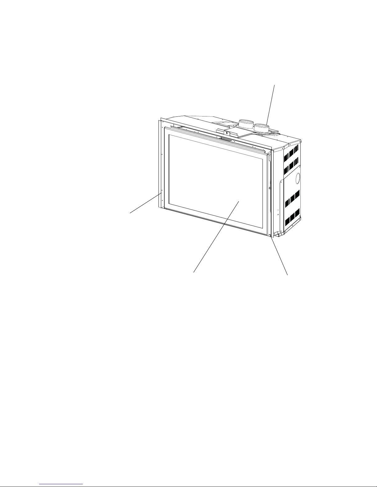
1.0 INSTALLATION OVERVIEW
3
Venting, see “INSTALLATION
- CHIMNEY CONNECTION”
section.
Rating Plate, see “RATING
PLATE INFORMATION”
section.
Logs, see “FINISHING - LOG
PLACEMENT” section.
Batteries, see “BATTERY INSTALLATION (IR3 only) section.
W415-1033 / A / 10.12.11
Page 4

4
2.0 INTRODUCTION
• THIS APPLIANCE IS HOT WHEN OPERATED AND CAN CAUSE SEVERE BURNS IF CONTACTED.
• ANY CHANGES OR ALTERATIONS TO THIS APPLIANCE OR ITS CONTROLS CAN BE DANGEROUS
AND IS PROHIBITED.
• Do not operate appliance before reading and understanding operating instructions. Failure to operate
appliance according to operating instructions could cause fi re or injury.
• Risk of fi re or asphyxiation do not operate appliance with fi xed glass removed.
• Do not connect 110 volts to the control valve.
• Risk of burns. The appliance should be turned off and cooled before servicing.
• Do not install damaged, incomplete or substitute components.
• Risk of cuts and abrasions. Wear protective gloves and safety glasses during installation. Sheet metal edges
may be sharp.
• Do not burn wood or other materials in this appliance.
• Children and adults should be alerted to the hazards of high surface temperature and should stay away to
avoid burns or clothing ignition.
• Young children should be carefully supervised when they are in the same room as the appliance. Toddlers,
young children and others may be susceptible to accidental contact burns. A physical barrier is recommended
if there are at risk individuals in the house. To restrict access to an appliance, install an adjustable safety gate
to keep toddlers, young children and other at risk individuals out of the room and away from hot surfaces.
• Clothing or other fl ammable material should not be placed on or near the appliance.
• Due to high temperatures, the appliance should be located out of traffi c and away from furniture and draperies.
• Ensure you have incorporated adequate safety measure to protect infants/toddlers from touching hot surfaces.
• Even after the appliance is out, the glass and/or screen will remain hot for an extended period of time.
• Check with your local hearth specialty dealer for safety screens and hearth guards to protect children from hot
surfaces. These screens and guards must be fastened to the fl oor.
• Any safety screen or guard removed for servicing must be replaced prior to operating the appliance.
• The appliance is a vented gas-fi red appliance. Do not burn wood or other materials in the appliance
• It is imperative that the control compartments, burners and circulating blower and its passageway in the
appliance and venting system are kept clean. The appliance and its venting system should be inspected
before use and at least annually by a qualifi ed service person. More frequent cleaning may be required due
to excessive lint from carpeting, bedding material, etc. The appliance area must be kept clear and free from
combustible materials, gasoline and other fl ammable vapors and liquids.
• Under no circumstances should this appliance be modifi ed.
• This appliance must not be connected to a chimney fl ue pipe serving a separate solid fuel burning appliance.
• Do not use this appliance if any part has been under water. Immediately call a qualifi ed service technician to
inspect the appliance and to replace any part of the control system and any gas control which has been under
water.
• Do not operate the appliance with the glass door removed, cracked or broken. Replacement of the glass
should be done by a licensed or qualifi ed service person.
• Do not strike or slam shut the appliance glass door.
• When equipped with pressure relief doors, they must be kept closed while the appliance is operating to
prevent exhaust fumes containing carbon monoxide, from entering into the home. Temperatures of the exhaust
escaping through these openings can also cause the surrounding combustible materials to overheat and catch
fi re.
• Only doors / optional fronts certifi ed with the unit are to be installed on the appliance.
• Keep the packaging material out of reach of children and dispose of the material in a safe manner. As with all
plastic bags, these are not toys and should be kept away from children and infants.
• As with any combustion appliance, we recommend having your appliance regularly inspected and serviced as
well as having a Carbon Monoxide Detector installed in the same area to defend you and your family against
Carbon Monoxide.
• Ensure clearances to combustibles are maintained when building a mantel or shelves above the appliance.
Elevated temperatures on the wall or in the air above the appliance can cause melting, discolouration or
damage of decorations, a T.V. or other electronic components.
!
WARNING
W415-1033 / A / 10.12.11
3.2B
Page 5
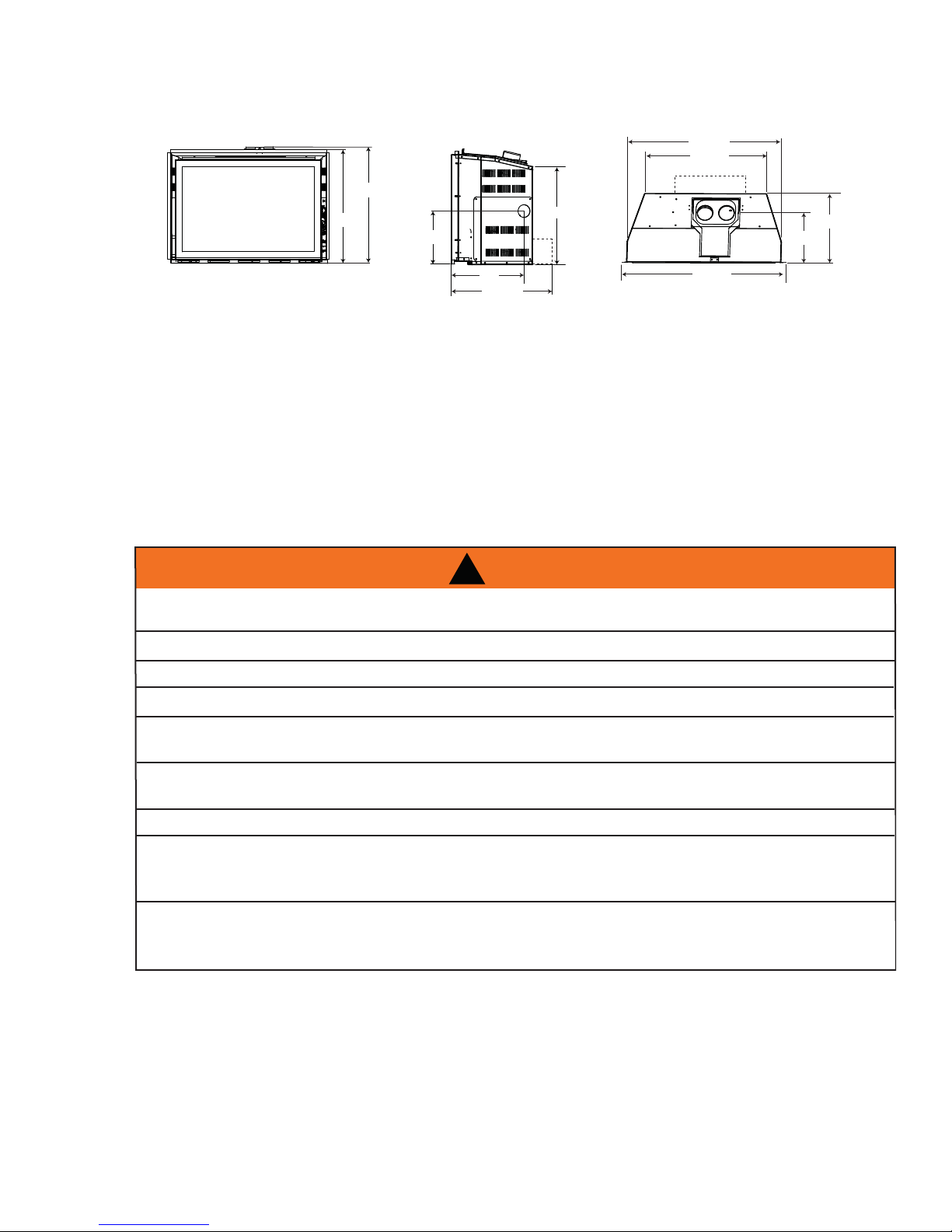
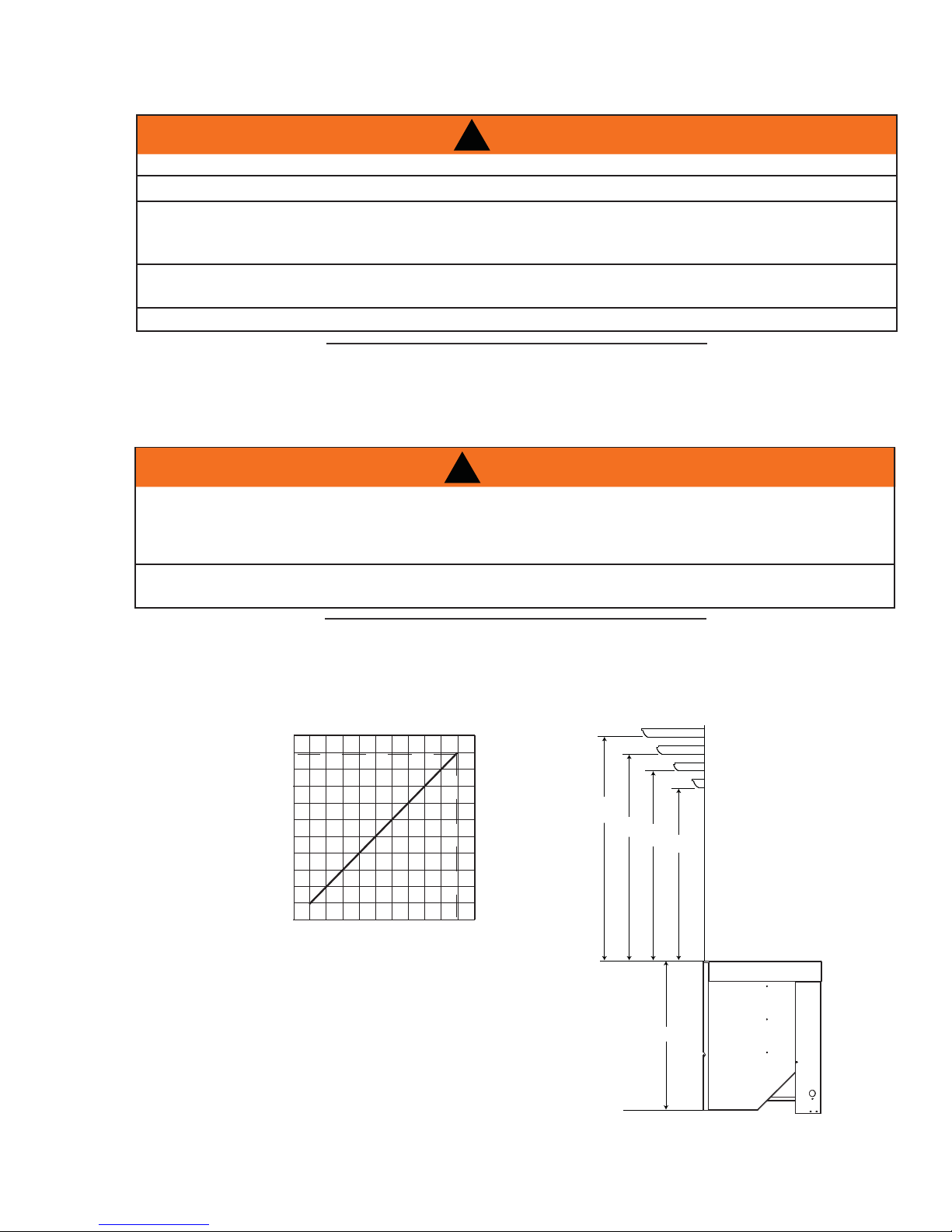
2.1 DIMENSIONS
201/2”
21”
91/2”
171/2”
5
283/4”
227/8”
131/4”
91/2”
12”
171/2”
2.2 MINIMUM CLEARANCE TO COMBUSTIBLES
This appliance must be recessed into a vented noncombustible wood-burning appliance (prefabricated or masonry)
only. The minimum appliance opening size in which the appliance is to be installed is:
HEIGHT 211/2" WIDTH 29" DEPTH *131/2"
The minimum allowable chimney fl ue size is 7" round.
*Add 4" for optional blower.
The minimum distance, from the bottom of a combustible mantel projecting 3" maximum from the wall to the
top of the appliance, is 14" (See MINIMUM MANTEL CLEARANCES section).
2.3 GENERAL INSTRUCTIONS
!
WARNING
ALWAYS LIGHT THE PILOT WHETHER FOR THE FIRST TIME OR IF THE GAS SUPPLY HAS RUN OUT,
WITH THE GLASS DOOR OPENED OR REMOVED.
PROVIDE ADEQUATE CLEARANCE FOR SERVICING AND OPERATING THE APPLIANCE.
PROVIDE ADEQUA TE VENTILA TION.
NEVER OBSTRUCT THE FRONT OPENING OF THE APPLIANCE.
295/8”
OBJECTS PLACED IN FRONT OF THE APPLIANCE MUST BE KEPT A MINIMUM OF 48” FROM THE
FRONT FACE OF THE UNIT.
SURFACES AROUND AND ESPECIALLY ABOVE THE APPLIANCE CAN BECOME HOT. AVOID CONTACT
WHEN THE APPLIANCE IS OPERATING.
FIRE RISK. EXPLOSION HAZARD.
HIGH PRESSURE WILL DAMAGE VALVE. DISCONNECT GAS SUPPLY PIPING BEFORE PRESSURE TESTING GAS
LINE AT TEST PRESSURES ABOVE 1/2 PSIG. CLOSE THE MANUAL SHUT-OFF VALVE BEFORE PRESSURE
TESTING GAS LINE AT TEST PRESSURES EQUAL TO OR LESS THAN 1/2 PSIG.
USE ONLY WOLF STEEL APPROVED OPTIONAL ACCESSORIES AND REPLACEMENT PARTS WITH THIS APPLIANCE.
USING NON-LISTED ACCESSORIES (BLOWERS, DOORS, LOUVRES, TRIMS, GAS COMPONENTS, VENTING
COMPONENTS, ETC.) COULD RESULT IN A SAFETY HAZARD AND WILL VOID THE WARRANTY AND CERTIFICATION.
THIS GAS APPLIANCE SHOULD BE INSTALLED AND SERVICED BY A QUALIFIED INSTALLER to
conform with local codes. Installation practices vary from region to region and it is important to know the
specifi cs that apply to your area, for example in Massachusetts State:
• This product must be installed by a licensed plumber or gas fi tter when installed within the commonwealth
of Massachusetts.
• The appliance damper must be removed or welded in the open position prior to installation of a appliance
insert or gas log.
• The appliance off valve must be a “T” handle gas cock.
• The fl exible connector must not be longer than 36 inches.
• A Carbon Monoxide detector is required in all rooms containing gas fi red appliances.
W415-1033 / A / 10.12.11
Page 6
6
Carbon Monoxide detector is required in all rooms containing gas fi red appliances.
A
A
A
• The appliance is not approved for installation in a bedroom or bathroom unless the unit is a direct vent
sealed combustion product.
The installation must conform with local codes or, in
absence of local codes, the National Gas and Propane
Installation Code CSA B149.1 in Canada, or the National
Fuel Gas Code, ANSI Z223.1 / NFPA 54 in the United
States. Suitable for mobile home installation if installed in
accordance with the current standard CAN/CSA Z240MH
Series, for gas equipped mobile homes, in Canada or
NSI Z223.1 and NFPA 54 in the United States.
s long as the required clearance to combustibles is
maintained, the most desirable and benefi cial location
for an appliance is in the center of a building, thereby
allowing the most effi cient use of the heat created. The location of windows, doors and the traffi c fl ow in the
room where the appliance is to be located should be considered. If possible, you should choose a location
where the vent will pass through the house without cutting a fl oor or roof joist.
If the appliance is installed directly on carpeting, vinyl tile or other combustible material other than wood
fl ooring, the appliance shall be installed on a metal or wood panel extending the full width and depth.
Some appliances have optional fans or blowers. If an optional fan or blower is installed, the junction box must
be electrically connected and grounded in accordance with local codes, use the current CSA C22.1 Canadian
Electrical Code in Canada or the ANSI/NFPA 70 National Electrical code in the United States.
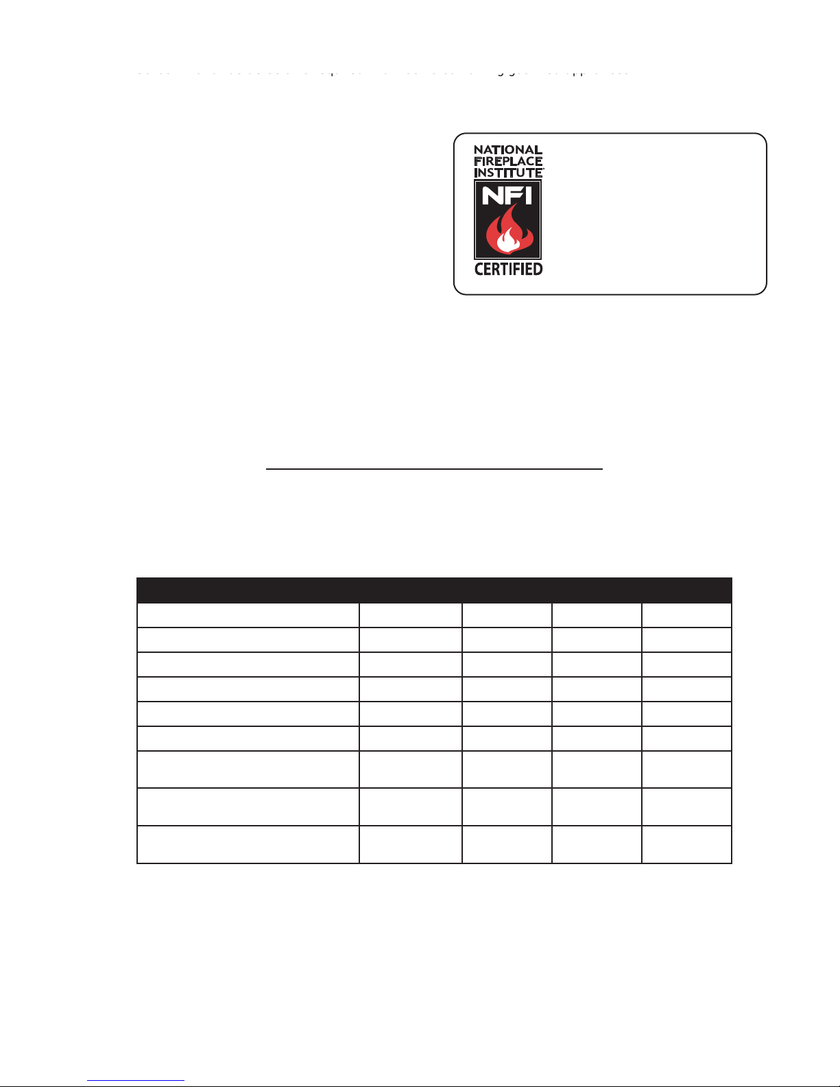
www.ncertied.org
We suggest that our gas
hearth products be installed
and serviced by professionals
who are certied in the U.S.
by the National Fireplace
Institute
®
(NFI) as NFI Gas
Specialists
4.1A
2.4 GENERAL INFORMATION
FOR YOUR SA TISFACTION, THIS APPLIANCE HAS BEEN TEST-FIRED TO ASSURE ITS OPERATION AND
QUALITY!
XIR3 IR3
NG LP NG LP
Altitude (FT) 0-4,500 0-4,500 0-4,500 0-4,500
Max. Input (BTU/HR) 31,000 31,000 24,000 24,000
Max. Output (BTU/HR) 24,800 24,800 18,480 18,480
Efficiency (w/the fan on) 80% 80% 77% 77%
A.F.U.E. (maximum value) 77% 77% 76% 76%
Min. Inlet Gas Supply Pressure 4.5" Water
Column
Max. Inlet Gas Supply Pressure 7" Water
Column
Manifold Pressure (Under Flow
Conditions)
3.5" Water
Column
11" Water
Column
13" Water
Column
10" Water
Column
4.5" Water
Column
7" Water
Column
3.5" Water
Column
11" Water
Column
13" Water
Column
10" Water
Column
W415-1033 / A / 10.12.11
Page 7
7
SA
XIR3PXIR3P
6
ProPro
L / APPAREIL
À GAZ VE À GA
EEL LTD.
L LTD.
SING THE APPROPRIATE WOLF STEEL VENT KITHE APPROPRIATE WOLF STEEL VENT KI
FOR VENTING SPECIFICS. PROPER REINSTALLANG SPECIFICS. PROPER REINSTALL
N INTO A VENTED NON-COMBUSTIBLE FIREPLACNON-COMBUSTIBLE FIREPLA
IS: HEIGHT 20.5”, DEPTH 13.25”, WIDTH 29”. THES: HEIGHT 20.5”, DEPTH 13.25”, WIDTH
T - GZ550-KT, GD65.
4500F500
UT/ALIMENTATION ALIMENTATION
INPUT/ALIMENTATION REDUITE NPUT/ALIMENTATION REDU
WATER COLUMNWATER COLUMN
7.0” WATER COLUMNTER COLUMN
D’UNE COLONNE D’EAUD’UNE COLONNE D’EAU
AFUE:FUE:
% 68.4%
M
:MANIFOLD P
10”
PRESSION AU COLLECTPRESSION AU
MINIMUM SUPPLY PRENIMUM SUPPLY
PRESSION D’ALIMESSION D’ALIM
MAXIMUM SUPPLMAXIMUM SUPP
PERSSION D’APERSSION D’A
:AFUE:
68.4%
SE WITH SOLID FUEL.SOLID FUEL.
CE FOYCE FO
CONCON
E. HOMOLOGUÉ POUR INSTALLATION DANS
OLOGUÉ POUR INSTALLATION DANS
MAISONS MOBILES ÉQUIPÉES AU GAZ, ENMAISONS MOBILES ÉQUIPÉES AU GAZ, EN
ÉTATS-UNIS, SELON LA NORME DE SÉCÉTATS-UNIS, SELON LA NORME DE SÉC
MAISONS MANUFACTURÉES, TITRE 2MAISONS MANUFACTURÉES, TITRE 2
OÙ CETTE NORME DES ÉTATS-UNISOÙ CETTE NORME DES ÉTATS-UNI
RÉFÉRER À LA NORME RELATIVERÉFÉRER À LA NORME RELATIV
CONTRE L'INCENDIE POUR LECONTRE L'INCENDIE POUR LE
MANUFACTURÉES, LES SITEANUFACTURÉES, LES SIT
CEAP
LWIL
LL
COMECOME
N
THTHAATT
SUPP
Y
THE MANUE MANUFFACTURERACT
When the appliance is installed at elevations above 4,500ft, and in the absence of specific recommendations
from the local authority having jurisdiction, the certified high altitude input rating shall be reduced at the rate of
4% for each additional 1,000ft. Expansion / contraction noises during heating up and cooling down cycles are
normal and to be expected.
This appliance is not approved for closet or recessed installations. It is approved for bathroom, bedroom and
bed-sitting room installations and is suitable for mobile homes. The natural gas model is suitable for installation
in a mobile home that is permanently positioned on its site and fuelled with natural gas.
67.0%
XIR3
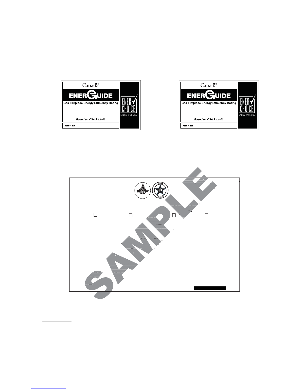
2.5 RATING PLATE INFORMATION
CERTIFIED UNDER / HOMOLOGUÉ SELON LES NORMES: ANSI Z21.88b-2009, CSA 2.22b-2009 VENTED GAS FIREPLACE / APPAREIL À GAZ V E N T I L É S .
DO NOT TURN ON IF CHILDREN OR OTHER AT RISK INDIVIDUALS
ARE NEAR THE FIREPLACE. DIRECT VENT GAS FIREPLACE
HEATER. SUITABLE FOR BEDROOM, BATHROOM AND BED-SITTING
ROOM INSTALLATION. SUITABLE FOR MOBILE HOME INSTALLATION
IF INSTALLED IN ACCORDANCE WITH THE CURRENT STANDARD
CAN/CSA Z240MH SERIES GAS EQUIPPED MOBILE HOMES, IN
CANADA OR IN THE UNITED STATES THE MANUFACTURED HOME
CONTRUCTION AND SAFETY STANDARD, TITLE 24 CFR, PART 3280.
WHEN THIS US STANDARD IS NOT APPLICABLE USE THE
STANDARD FOR FIRE SAFETY CRITERIA FOR MANUFACTURED
HOME INSTALLATIONS, SITES AND COMMUNITIES, ANSI / NFPA
501A.
THIS VENTED GAS FIREPLACE HEATER IS NOT FOR USE
WITH AIR FILTERS. FOR USE WITH GLASS DOORS CERTIFIED
FOR THIS UNIT ONLY. NOT FOR USE WITH SOLID FUEL.
WARNING: DO NOT ADD ANY MATERIAL TO THE APPLIANCE THAT WILL COME IN
CONTACT WITH THE FLAMES, OTHER THAN THAT SUPPLIED BY THE MANUFACTURER
WITH THE APPLIANCE.
ELECTRICAL RATING: 115V 1.5AMP 60HZ
THE APPLIANCE MUST BE VENTED USING THE APPROPRIATE WOLF STEEL VENT KITS. SEE
OWNER’S INSTALLATION MANUAL FOR VENTING SPECIFICS. PROPER REINSTALLATION AND
RESEALING IS NECESSARY AFTER SERVICING THE VENT-AIR INTAKE SYSTEM.
WARNING: FOR INSTALLATION INTO A VENTED NON-COMBUSTIBLE FIREPLACE ONLY. THE
MINIMUM FIREPLACE SIZE IS: HEIGHT 20.5”, DEPTH 13.25”, WIDTH 29”. THE MINIMUM INSIDE
FLUE SIZE IS 6”. THE MINIMUM DISTANCE FROM THE BOTTOM OF A COMBUSTIBLE MANTEL
PROJECTING A MAXIMUM 3” FROM THE WALL TO THE TOP OF THE UNIT IS 12”. SEE OWNER’S
MANUAL FOR GREATER EXTENSIONS.
OPTIONAL FAN KIT - GZ550-KT, GD65.
WOLF STEEL LTD.
24 NAPOLEON ROAD, BARRIE. ONTARIO L4M 4Y8 CANADA
Natural Gas/Gaz Naturel Propane
XIR3N XIR3PCXIR3N CXIR3PMODEL
PRESSION D’ALIMENTATION MINIMALE: 4.5” D’UNE COLONNE D’EAU
PERSSION D’ALIMENTATION MAXIMALE: 7.0” D’UNE COLONNE D’EAU
4500FT (0-1370m) ALTITUDE/ELEVATION 4500FT (0-1370m)
31,000 BTU/h INPUT/ALIMENTATION 31,000 BTU/h
11,000 BTU/h REDUCED INPUT/ALIMENTATION REDUITE 16,000 BTU/h
MANIFOLD PRESSURE: 3.5” WATER COLUMN
PRESSION AU COLLECTEUR: 3.5” D’UNE COLONNE D’EAU
MINIMUM SUPPLY PRESSURE: 4.5” WATER COLUMN
MAXIMUM SUPPLY PRESSURE: 7.0” WATER COLUMN
APPLIAN
SUPPLIED B
THATWI
CERTIFIED FOR
CERTIFIEE POUR
CERTIFIED
REFERENCE #161746
AFUE: 68.4%
68.4
I
64.0%
IR3
NE PAS ALLUMER SI DES ENFANTS OU D’AUTRES INDIVIDUS À RISQUE
SONT À PROXIMITÉ DU FOYER. APPAREIL DE CHAUFFAGE À ÉVACUATION
DIRECTE. HOMOLOGUÉ POUR INSTALLATION DANS UNE CHAMBRE À
COUCHER, UNE SALLE DE BAIN ET UN STUDIO. APPROPRIÉ POUR
INSTALLATION DANS UNE MAISON MOBILE SI SON INSTALLATION EST
CONFORME AUX EXIGENCES DE LA NORME CAN/CSA Z240MH SÉRIE DE
MAISONS MOBILES ÉQUIPÉES AU GAZ, EN VIGUEUR AU CANADA, OU AUX
ÉTATS-UNIS, SELON LA NORME DE SÉCURITÉ ET DE CONSTRUCTION DE
CANADA USA
MANIFOLD PRESSURE: 10” WATER COLUMN
PRESSION AU COLLECTEUR: 10” D’UNE COLONNE D’EAU
MINIMUM SUPPLY PRESSURE: 11” WATER COLUMN
PRESSION D’ALIMENTATION MINIMALE: 11” D’UNE COLONNE D’EAU
MAXIMUM SUPPLY PRESSURE: 13” WATER COLUMN
PERSSION D’ALIMENTATION MAXIMALE: 13” D’UNE COLONNE D’EAU
AFUE: 68.4%
AFUE
CE FOYER À GAZ VENTILÉS NE DOIT PAS ÊTRE UTILISÉ
CONJOINTEMENT AVEC DES FILTRES À AIR. UTILISER AVEC LES
PORTES VITRÉES HOMOLOGUÉES AVEC CETTE UNITÉ SEULEMENT. UN COMBUSTIBLE SOLIDE NE DOIT PAS ETRE UTILISE
AVEC CET APPAREIL.
AVERTISSEMENT:
ENTRER EN CONTACT AVEC LES FLAMMES AUTRE QUE CELUI QUI EST FOURNI A VEC CET
APPAREIL PAR LE FABRICANT.
CLASS : 115V, 1.5AMP, 60HZ
L’APPAREIL DOIT EVACUER SES GAZ EN UTILISANT L’ENSEMBLE D’EVACUATION PROPRE A WOLF STEEL.
REFERER AU MANUEL D’INSTALLATION DE PROPRIETAIRE POUR L’EVACUATION PRECISE. IL EST IMPORTANT DE
BIEN REINSTALLER ET RESCELLER L’EVENT APRES AVOIR ASSURE LE MAINTIEN DU SYSTEME DE PRISE D’AIR.
ATTENTION : POUR INSTALLATION DANS UN FOYER VENTILE EN MACONNERIE. LES DIMENSIONS MINIMUMS
SONT: HAUTER 19.75”, PROFONDEUR 13.25”, LARGEUR 29”. LE DIAMETRE INTERIEUR MINIMUM DE CONDUIT
D’EVACUATION EST DE 6”. LA DISTANCE MINIMALE, DU BAS DU MANTEAU COMBUSTIBLE FORMANT UNE
PROJECTION MAXIMALE DE 3” DU MUR AU DESSUS DE LA GARNITURE NORMALE EST 12”. REFERER AU MANUEL
D’INSTALLATION POUR DES EXTENSIONS PLUS GRANDES.
SOUFFLERIE OPTIONELLE
SERIAL NUMBER/NO. DE SERIE: XIR3/CXIR3
MAISONS MANUFACTURÉES, TITRE 24 CFR, SECTION 3280. DANS LE CAS
OÙ CETTE NORME DES ÉTATS-UNIS NE PEUT ÊTRE APPLIQUÉE, SE
RÉFÉRER À LA NORME RELATIVE AU CRITÈRE DE MESURES DE SÉCURITÉ
CONTRE L'INCENDIE POUR LES INSTALLATIONS DANS LES MAISONS
MANUFACTURÉES, LES SITES ET LES COMMUNAUTÉS, ANSI/NFPA 501A.
ANIFOLD PRESSURE
N'A JOUTEZ PAS A CET APPAREIL AUCUN MATERIAU DEVANT
GZ550-KT, GD65.
/ APPAREI
W385-0661
INSTALLER: It is your responsibility to check off the appropriate box on the rating plate according to
the model, venting and gas type of the appliance.
For rating plate location, see “INSTALLATION OVERVIEW” section.
This illustration is for reference only. Refer to the rating plate on the appliance for accurate information.
W415-1033 / A / 10.12.11
Page 8
8
3.0 INSTALLATION
RISK OF FIRE, MAINTAIN SPECIFIED AIR SPACE CLEARANCES TO VENT PIPE AND APPLIANCE.
Clean out ashes from the inside of the wood-burning appliance. Make sure that the chimney and wood-burning
appliance are in a clean and sound condition and constructed of non-combustible materials. If necessary have
any repair work done by a qualifi ed person before installing the insert. Remove the existing appliance damper
or lock into an open position.
Using screws, attach the appliance warning tag
to the inside of the fi rebox of the appliance into
which the insert is being installed.
The sheet-metal parts of the appliance, in which
the gas appliance insert is to be installed, must
not be cut.
If the wood-burning factory-built appliance has
no gas access hole(s) provided, an access hole of 1½ inch or less may be drilled through the lower sides or
bottom of the appliance in a proper workman like manner. This access hole must be plugged with non-combustible insulation after the gas supply line has been installed.
!
WARNING
WARNING: THIS FIREPLACE HAS BEEN CONVERTED FOR USE WITH A GAS FIREPLACE
INSERT ONLY AND CANNOT BE USED FOR BURNING WOOD OR SOLID FUELS UNLESS ALL ORIGINAL
PARTS HAVE BEEN REPLACED AND THE FIREPLACE IS RE-APPROVED BY THE AUTHORITY HAVING
JURISDICTION.
ATTENTION: CE FOYER A ETE CONVERTI AFIN D’ETRE UTILISE SEULEMENT
COMME FOYER ENCASTRE AU GAZ ET NE PEUT ETRE UTILSE POUR BRULER DU BOIS OU
TOUT AUTRE COMBUSTIBLE SOLIDE, SANS QUE TOUTES LES PIECES ORIGINALES AIENT
ETE REMPLACEES ET QUE LE FOYER SOIT APPROUVE DE NOUVEAU PAR LES AUTORITES
AYANT JURIDICTION.
ADVERTENCIA: ESTA CHIMENEA SE REMODELÓ PARA USARSE SOLO CON UNA
INSERCIÓN DE CHIMENEA A GAS Y NO PUEDE USARSE PARA QUEMAR MADERA NI COMBUSTIBLES
SÓLIDOS, A MENOS QUE SE HAYAN REEMPLAZADO TODAS LAS PIEZAS ORIGINALES, Y LA AUTORIDAD JURISDICCIONAL LA HAYA VUELTO A APROBAR.
W385-0199_B
Ensure that existing chimney cleanouts fi t properly .
The refractory, glass doors, screen rails, screen mesh and log grates may be removed from the existing appli-
ance before installing the gas appliance insert.
Smoke shelves, shields and baffl es may be removed if attached by mechanical fasteners.
The ventilation openings in the existing appliance may be obstructed by the backer plates, aluminium trim etc.
but these parts are not to be applied so as to have an airtight seal.
3.1 LEVELLING THE APPLIANCE
Move the appliance close to its fi nal position. This appliance is equipped with levelling screws located on the
base. Level using the levelling screws. Levelling the appliance will eliminate rocking or excessive noise when
the fan is in operation. Once the appliance is level, move it partially into place to allow for all connections to be
made. It is not practical to level the appliance once it has been installed. Determine the required depth prior to
installing the appliance and adjust the levelling screws accordingly.
68.4A
67.2
W415-1033 / A / 10.12.11
Page 9
3.2 CHIMNEY CONNECTION
Chimney installation must conform to both national and local code requirements. The chimney must be lined
with one 3" diameter liner for intake and one 3" diameter liner for exhaust. The minimum and maximum vent
lengths are 10 and 35 feet respectively. Recommended kits come in 3 lengths:
2-3" DOUBLE PLY ALUMINUM LINER-INLET AND EXHAUST:
While the liners must be continuous from the appliance to the chimney cap, to
achieve the needed length, they may be coupled, using an approved coupler.
We recommend that exhaust vents that pass through unheated spaces,
such as tall exterior chimneys, be wrapped in a protective sleeve to minimize
condensation and reverse flow symptoms. See Trouble Shooting for details.
This appliance is approved for use with a 3" exhaust and air intake.
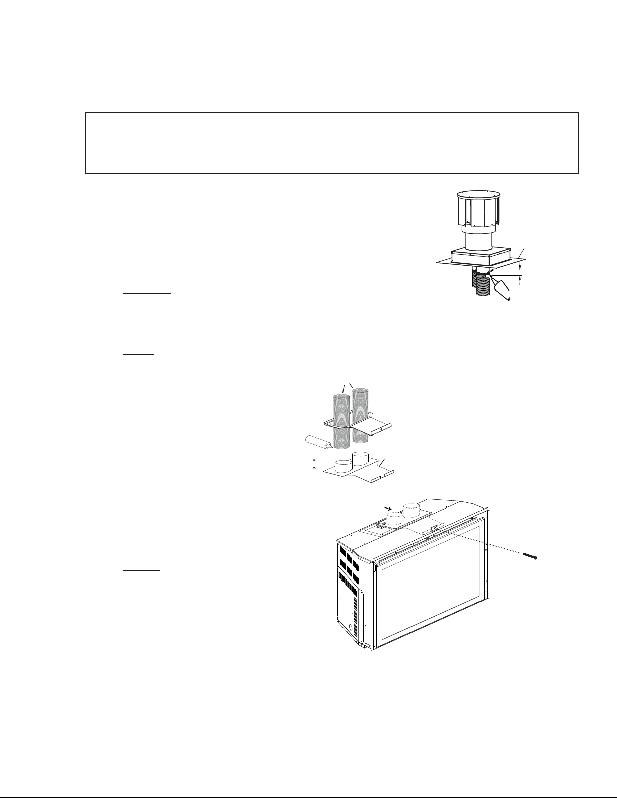
A. OUTSIDE: Slip the one end of a liner a minimum of 2" over the
sleeve of the air terminal. Secure using 3 screws. Then seal the
joint and screw heads with high temperature sealant. Repeat with
the other liner.
GDI-320KT VENT KIT 20FT
GDI-325KT VENT KIT 25 FT
GDI-335KT VENT KIT 35 FT
EXHAUST
INTAKE
9
FLASHING
PLATE
2” OVERLAP
SEALANT
HI-TEMP
NOTE: We recommend that the other end of the exhaust liner be marked to eliminate the
exhaust liner being connected
to the intake collar at the
3”
LINERS
appliance.
B. Gently stretch the liners to the
required lengths and insert
into the chimney. Trim and fi t
the fl ashing plate to suit the
chimney termination. Place
HIGH TEMP
SEALANT
2”
OVERLAP
SLIDER
MOUNTING
PLATE
the air terminal onto the top
of the chimney. Make weather
tight by sealing with caulking
INTAKE
(not supplied). Fasten to the
chimney with screws and plugs
EXHAUST
(not supplied).
C. INSIDE: Remove the securing
screw from the front of the vent
mounting plate. Pull the vent
mounting plate only, back into
the track, to the front stop. Start
the slider back into position. Resecure the screw. The appliance
may now be pushed into its fi nal position inside the wood burning appliance, and the screw tightened
until the slider has been pulled tight to the front stop.
SECURING
SCREW
D. Route the fl ex liners through the slider. Attach and secure the liners to the vent mounting plate using
the same procedure as before, ensuring that the marked exhaust liner is attached to the exhaust collar.
W415-1033 / A / 10.12.11
Page 10
10
3.3 GAS INSTALLATION
RISK OF FIRE, EXPLOSION OR ASPHYXIATION. ENSURE THERE ARE NO IGNITION SOURCES SUCH AS
SUPPORT GAS CONTROL WHEN ATTACHING GAS SUPPLY PIPE TO PREVENT DAMAGING GAS LINE.
ALWAYS LIGHT THE PILOT WHETHER FOR THE FIRST TIME OR IF THE GAS SUPPLY HAS RUN OUT
WITH THE GLASS DOOR OPENED OR REMOVED. PURGING OF THE GAS SUPPLY LINE SHOULD BE
PERFORMED BY A QUALIFIED SERVICE TECHNICIAN. ASSURE THAT A CONTINUOUS GAS FLOW IS AT
THE BURNER BEFORE CLOSING THE DOOR. ENSURE ADEQUATE VENTILATION. FOR GAS AND
ELECTRICAL LOCATIONS, SEE “DIMENSION” SECTION.
ALL GAS CONNECTIONS MUST BE CONTAINED WITHIN THE APPLIANCE WHEN COMPLETE.
HIGH PRESSURE WILL DAMAGE VALVE. DISCONNECT GAS SUPPLY PIPING BEFORE TESTING GAS
VALVE SETTINGS HAVE BEEN FACTORY SET, DO NOT CHANGE.
Installation and servicing to be done by a qualifi ed installer.
A. Move the appliance into position and secure.
B. If equipped with a fl ex connector the appliance is designed to accept a 1/2” gas supply. Without the
connector it is designed to accept a 3/8” gas supply. The appliance is equipped with a manual shut off
valve to turn off the gas supply to the appliance.
C. Connect the gas supply in accordance to local codes. In the absence of local codes, install to the
current CAN/CSA-B149.1 Installation Code in Canada or to the current National Fuel Gas Code, ANSI
Z223.1 / NFPA 54 in the United States.
D. When fl exing any gas line, support the gas valve so that the lines are not bent or kinked.
E. The gas line fl ex-connector should be installed to provide suffi cient movement for shifting the burner
assembly on it’s side to aid with servicing components.
F. Check for gas leaks by brushing on a soap and water solution. Do not use open fl ame.
!
WARNING
SPARKS OR OPEN FLAMES.
LINE AT TEST PRESSURES ABOVE 1/2 PSIG.
30.1A
W415-1033 / A / 10.12.11
Page 11
4.0 FINISHING
NEVER OBSTRUCT THE FRONT OPENING OF THE APPLIANCE.
THE FRONT OF THE APPLIANCE MUST BE FINISHED WITH ANY NON-COMBUSTIBLE MATERIALS
SUCH AS BRICK, MARBLE, GRANITE, ETC., PROVIDED THAT THESE MATERIALS DO NOT GO
BELOW THE SPECIFIED DIMENSION AS ILLUSTRATED.
DO NOT STRIKE, SLAM OR SCRATCH GLASS. DO NOT OPERATE APPLIANCE WITH GLASS
REMOVED, CRACKED, BROKEN OR SCRATCHED.
FACING AND/OR FINISHING MATERIAL MUST NEVER OVERHANG INTO THE APPLIANCE OPENING.
4.1 MINIMUM MANTEL CLEARANCES
RISK OF FIRE, MAINTAIN ALL SPECIFIED AIR SPACE CLEARANCES TO COMBUSTIBLES. FAILURE
TO COMPLY WITH THESE INSTRUCTIONS MAY CAUSE A FIRE OR CAUSE THE APPLIANCE TO
OVERHEAT. ENSURE ALL CLEARANCES (I.E. BACK, SIDE, TOP, VENT, MANTEL, FRONT, ETC.) ARE
CLEARLY MAINTAINED.
WHEN USING PAINT OR LACQUER TO FINISH THE MANTEL, THE PAINT OR LACQUER MUST BE
HEAT RESISTANT TO PREVENT DISCOLOURATION.
!
WARNING
RISK OF FIRE!
!
WARNING
11
72.1A
73.1
Combustible mantel clearance can vary according to the mantel depth. Use the graph to help evaluate the
clearance needed. These same requirements apply to any combustibles protruding on either side of the
appliance.
6” MANTEL
16”
5”
15”
4”
3”
14”
0
$
1
7
(
17
+
(
16
,
17”
*
15
+
7
/
14
0
3
4
5
6
MANTEL DEPTH
201/2”
W415-1033 / A / 10.12.11
Page 12

12
4.2 DOOR REMOVAL AND INSTALLATION
!
WARNING
GLASS MAY BE HOT, DO NOT TOUCH GLASS UNTIL COOLED.
THE DOOR LATCHES ARE PART OF A SAFETY SYSTEM AND MUST BE PROPERLY ENGAGED. DO
NOT OPERATE THE APPLIANCE WITH LATCHES DISENGAGED.
FACING AND/OR FINISHING MATERIALS MUST NOT INTERFERE WITH AIR FLOW THROUGH AIR
OPENINGS, LOUVRES OPENINGS, OPERATION OF LOUVRES OR DOORS OR ACCESS FOR
SERVICE. OBSERVE ALL CLEARANCES WHEN APPLYING COMBUSTIBLE MATERIALS.
BEFORE DOOR IS REMOVED TURN THE APPLIANCE OFF AND WAIT UNTIL APPLIANCE IS COOL TO
THE TOUCH. DOORS ARE HEAVY AND FRAGILE SO HANDLE WITH CARE.
The optional front must be removed to allow the door to be opened
or closed. Release the top left and right door latches, located at the
top of the door. Tilt forward and lift from slots.
75.1
DOOR LATCH
W415-1033 / A / 10.12.11
Page 13
4.3 IR3 LOG PLACEMENT
FAILURE TO POSITION THE LOGS IN ACCORDANCE WITH THESE DIAGRAMS OR FAILURE TO USE
ONLY LOGS SPECIFICALLY APPROVED WITH THIS APPLIANCE MAY RESULT IN PROPERTY
LOGS MUST BE PLACED IN THEIR EXACT LOCATION IN THE APPLIANCE. DO NOT MODIFY THE
PROPER LOG POSITIONS, SINCE APPLIANCE MAY NOT FUNCTION PROPERLY AND DELAYED
THE LOGS ARE FRAGILE AND SHOULD BE HANDLED WITH CARE.
PHAZERTM logs and glowing embers exclusive to Napoleon, provide a unique and realistic glowing effect that is
different in every installation. Take the time to carefully position the glowing embers for a maximum glowing effect.
Log colours may vary. During the initial use of the appliance, the colours will become more uniform as colour
pigments burn in during the heat activated curing process.
!
WARNING
DAMAGE OR PERSONAL INJURY.
IGNITION MAY OCCUR.
13
76.1A
LOG SUPPORT
A. Place the rear log behind the left
and right log supports and ensure
that it's tight to the burner. Make sure
to centre the pilot in the notch. Adjust
the log supports tight to the log to
hold it in an upright position.
D. Position the left charcoal strip in
front of the left middle log, lining up
the holes in the bottom with the 2
front left studs.
B. Place the left middle log into
position, lining up the two holes in
the bottom with the studs located
on the left side of the burner.
E. Position the right charcoal strip
in front of the right middle log, lining
up the holes in the bottom with the
2 front right studs.
C. Place the right middle log into
position, lining up the two holes in
the bottom with the studs located on
the right side of the burner.
F. Position a pin (supplied) into the
left side hole of the rear log, move
the left crossover log into position,
lining up the top hole with the pin in
the rear log.
G. Position a pin into the right side
hole of the rear log, move the right
crossover log into position, lining
up the top hole with the pin in the
rear log.
W415-1033 / A / 10.12.11
Page 14
14
4.4 XIR3 LOG PLACEMENT
PIN
LOG SUPPORT
A. Place the rear log into position
lining up the holes in the bottom
with the studs located at the rear of
the firebox. Ensure it is tight to the
burner.
D. Place the left front log into
position, lining up the 2 holes in the
bottom with the studs located on
the left side of the burner.
B. Place the left middle log behind
the left log support. Insert a pin
(supplied) into the right end of the
log.
E. Place the right front log into
position, lining up the 2 holes in the
bottom with the studs located on
the right side of the burner.
C. Insert the right middle log end
onto the left log pin and place it
behind the right support. Adjust the
log supports tight to these logs to
hold them in an upright position and
ensure they are tight to the burner.
F. Position the left charcoal strip in
front of the left front log, lining up
the 2 holes in the bottom with the 2
front left studs.
G. Position the right charcoal strip
in front of the right front log, lining
up the 2 holes in the bottom with
the 2 front right studs.
W415-1033 / A / 10.12.11
H. Position a pin into the left side
hole of the left middle log, move
the left crossover log into position,
lining up the top hole with the pin.
I. Position a pin into the right side
hole of the right middle log, move
the right crossover log into position,
lining up the top hole with the pin.
Page 15

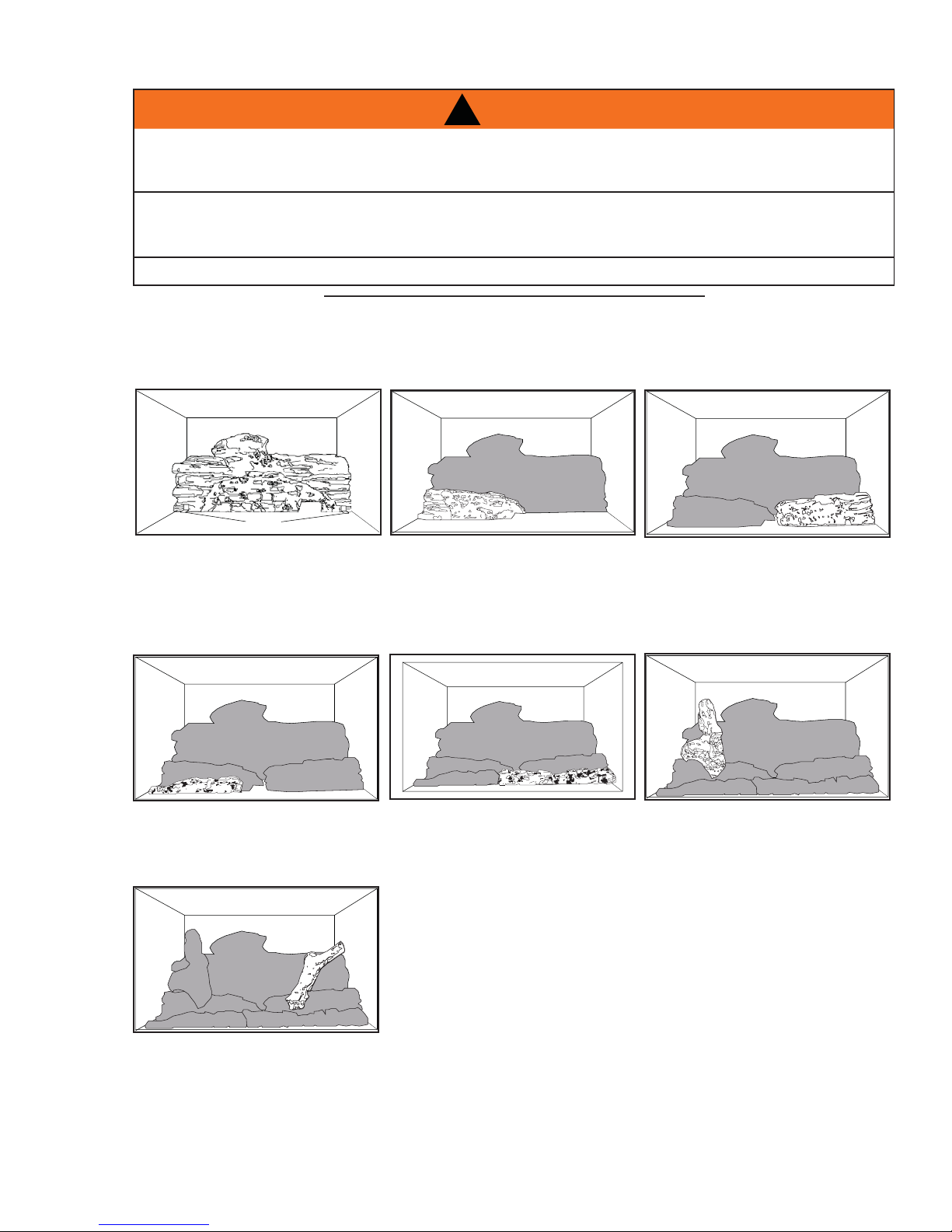
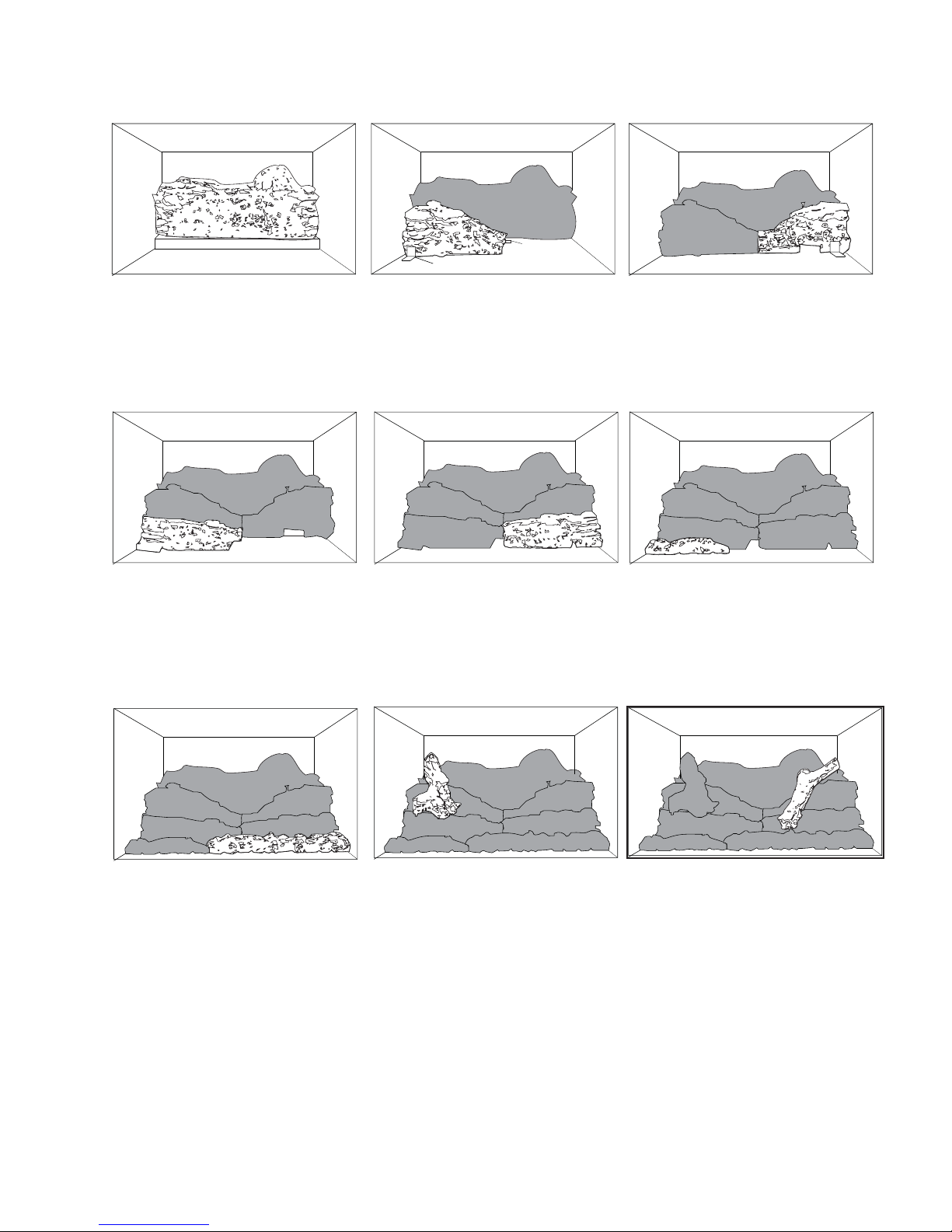
4.5 OPTIONAL ROCK PLACEMENT
REAL ROCKS MUST NOT BE USED IN THIS APPLIANCE. HEAT WILL CAUSE THEM TO EXPLODE
Before beginning with the installation, remove the door and all burner media from the appliance including logs
and charcoal strips. Retain the glowing embers.
A. Sit the two rock clusters on top of the rear log support. Ensure the clusters are sitting flat.
!
WARNING
15
B. Place the large notched rocks along the step behind the front burner as desired.
C. Place the remaining rocks around the burner as desired making sure not to cover any burner ports
(there are no set locations).
D. Reinstall the glowing embers over the burner.
E. Reinstall the door.
4.6 GLOWING EMBERS
Tear the embers into pieces and place along the front row of ports covering all of the burner area in front of
the small logs. Care should be taken to shred the embers into thin, small irregular pieces as only the exposed
edges of the fibre hairs will glow. The ember material will only glow when exposed to direct flame;
however, care should be taken to not block the burner ports.
Blocked burner ports can cause an incorrect flame pattern, carbon deposits and delayed ignition. PHAZERTM
logs glow when exposed to direct flame. Use only certified "glowing embers" and PHAZERTM logs available
from your authorized dealer / distributor.
4.7 LOGO PLACEMENT
Remove the backing of the logo supplied and place on the glass viewing door,
as indicated.
½"
LOGO
½"
97.1
W415-1033 / A / 10.12.11
Page 16

16
4.8 ON/OFF SWITCH INSTALLATION (IR3 ONLY)
Snap the ON/OFF switch into the slot located in the top right side of the surround. Run the two black wires
up the side of the surround, through the wire clips and connect to the switch terminals (see surround leaflet
instructions for details).
WIRE CLIPS
4.9 BATTERY INSTALLATION (XIR3 ONLY)
4 AA batteries must be installed into the receiver before operation is
possible in the XIR3. The receiver is located in the bottom left corner of
the appliance.
If receiver removal is necessary, remove the left access panel from the front
of the appliance. Remove the 2 screws holding the receiver in place. Pull
the receiver through the access hole and replace.
RECEIVER
RECEIVER PLATE
SCREWS
4.10 BATTERY INSTALLATION (IR3 ONLY)
4 AA batteries must be installed in to the DC battery pack before operation is possible in the IR3. The battery
pack is located in the bottom right corner of the appliance.
W415-1033 / A / 10.12.11
Page 17

5.0 ELECTRICAL INFORMATION
!
WARNING
DO NOT USE THIS APPLIANCE IF ANY PART HAS BEEN UNDER WATER. CALL A QUALIFIED
SERVICE TECHNICIAN IMMEDIATELY TO HAVE THE APPLIANCE INSPECTED FOR DAMAGE TO THE
ELECTRICAL CIRCUIT.
RISK OF ELECTRICAL SHOCK OR EXPLOSION. DO NOT WIRE 110V TO THE VALVE OR TO THE
APPLIANCE WALL SWITCH. INCORRECT WIRING WILL DAMAGE CONTROLS.
ALL WIRING SHOULD BE DONE BY A QUALIFIED ELECTRICIAN AND SHALL BE IN COMPLIANCE
WITH LOCAL CODES. IN THE ABSENCE OF LOCAL CODES, USE THE CURRENT CSA22.1 CANADIAN
ELECTRIC CODE IN CANADA OR THE CURRENT NATIONAL ELECTRIC CODE ANSI/NFPA NO. 70 IN
THE UNITED STATES.
ALWAYS LIGHT THE PILOT WHETHER FOR THE FIRST TIME OR IF THE GAS SUPPLY HAS RAN OUT,
WITH THE GLASS DOOR OPENED OR REMOVED.
5.1 WIRING DIAGRAM (IR3)
This appliance comes equipped with a battery pack. Install 4 AA batteries into the holder that is connected to
the wire harness. Place near the front of the appliance for ease of changing batteries.
17
69.2
DC BATTERY PACK
-
+
+
-
ON / OFF
SWITCH
(SUPPLIED
WITH TRIM)
ON / OFF
DISCONNECT THESE
CONNECTORS TO THE
ON/OFF SWITCH AND
CONNECT TO
OPTIONAL
THERMOSTAT OR
REMOTE .
GROUND
GROUND
EYELET
VALVE
ORANGE
GREEN
VALVE
ELECTRONIC
IPI BOARD
DFC
W415-1033 / A / 10.12.11
Page 18

18
5.2 WIRING DIAGRAM (XIR3)
This appliance comes equipped with a battery back-up. If this back-up is used, install 4 AA batteries (not
supplied) into the receiver.
ACS/IPI Switch
(OPTIONAL)
Fan
(OPTIONAL)
120V OUT
FAN
AUX OUT
POWER
COM
Wire
Harness
Plug
Control Module
Receiver
Wire Harness
Night Lights
Valve
Electronic Modulation
Wire Harness Assembly
Spark Electrode
Flame
Sensor
EI
Pilot
Pilot
Ground
Wire
IPI Board
W415-1033 / A / 10.12.11
Page 19

6.0 OPERATION
!
WARNING
IF YOU DO NOT FOLLOW THESE INSTRUCTIONS EXACTLY, A FIRE OR EXPLOSION MAY RESULT
CAUSING PROPERTY DAMAGE, PERSONAL INJURY OR LOSS OF LIFE.
ALWAYS LIGHT THE PILOT WHETHER FOR THE FIRST TIME OR IF THE GAS SUPPLY HAS RUN OUT WITH
THE GLASS DOOR OPENED OR REMOVED.
When lit for the first time, the appliance will emit a slight odour for a few hours. This is a normal temporary
condition caused by the "burn-in" of internal paints and lubricants used in the manufacturing process and
will not occur again. Simply open a window to sufficiently ventilate the room. After extended periods of nonoperation such as following a vacation or a warm weather season, the appliance may emit a slight odour for
a few hours. This is caused by dust particles in the heat exchanger burning off. Open a window to sufficiently
ventilate the room.
6.1 OPERATING AND LIGHTING INSTRUCTIONS
19
FOR YOUR SAFETY READ BEFORE OPERATING / POURVOTRE SÉCURITÉ LIRE AVANT DE FAIRE FONCTIONNER
OPERATING INSTRUCTIONS / INSTRUCTIONS D’OPERATION
WARNING: IF YOU DO NOT FOLLOW THESE INSTRUC-
TIONS EXACTLY, A FIRE OR EXPLOSION MAY RESULT
CAUSING PROPERTY DAMAGE, PERSONAL INJURY OR
LOSS OF LIFE.
INITIAL LIGHTING OF THE PILOT AND MAIN BURNERS
MUST BE DONE WITH THE GLASS DOOR OFF.
DO NOT CONNECT VALVE OR WALL SWITCH TO ELECTRICITY. SEE INSTALLATION INSTRUCTIONS.
A. THIS FIREPLACE IS EQUIPPED WITH AN IGNITION DEVICE WHICH AUTOMATICALLY LIGHTS THE PILOT. DO NOT TRY TO LIGHT BY HAND.
B. BEFORE OPERATING SMELL ALL AROUND THE FIREPLACE AREA FOR GAS
AND NEXT TO THE FLOOR BECAUSE SOME GAS IS HEAVIER THAN AIR AND WILL
SETTLE ON THE FLOOR.
WHAT TO DO IF YOU SMELL GAS:
TURN OFF ALL GAS TO THE FIREPLACE.
OPEN WINDOWS.
DO NOT TRY TO LIGHT ANY APPLIANCE.
DO NOT TOUCH ANY ELECTRIC SWITCH DO NOT USE ANY PHONE IN YOUR
BUILDING.
IMMEDIATELY CALL YOUR GAS SUPPLIER FROM A NEIGHBOUR¶S PHONE.
FOLLOW THE GAS SUPPLIER¶S INSTRUCTIONS.
IF YOU CANNOT REACH YOUR GAS SUPPLIER, CALL THE FIRE DEPARTMENT.
C. DO NOT TRY TO REPAIR ANY PART OF THIS ASSEMBLY. CALL A QUALIFIED
SERVICE TECHNICIAN. FORCE OR ATTEMPTED REPAIR MAY RESULT IN A FIRE
OR EXPLOSION.
D. DO NOT USE THIS FIREPLACE IF ANY PART HAS BEEN UNDER WATER.
IMMEDIATELY CALL A QUALIFIED SERVICE TECHNICIAN TO INSPECT THE
FIREPLACE AND REPLACE ANY PART OF THE CONTROL SYSTEM AND ANY GAS
CONTROL WHICH HAS BEEN UNDER WATER.
LIGHTING INSTRUCTIONS / INSTRUCTIONS D’ALLUMAGE
1. STOP! READ ALL INFORMATION OF OPERATING AND LIGHTING
INSTRUCTIONS BEFORE PROCEEDING.
2. TURN OFF ELECTRIC POWER TO THE FIREPLACE.
3. THIS FIREPLACE IS EQUIPPED WITH AN IGNITION DEVICE WHICH
AUTOMATICALLY LIGHTS THE PILOT. DO NOT TRY TO LIGHT THE PILOT
BY HAND.
4. OPEN THE GLASS DOOR.
5. TURN MANUAL SHUTOFF VALVE CLOCKWISE TO OFF.
6. WAIT FIVE (5) MINUTES TO CLEAR OUT ANY GAS. IF YOU SMELL GAS
INCLUDING NEAR THE FLOOR, STOP! FOLLOW “B” OF THE OPERATING
INSTRUCTIONS. IF YOU DON’T SMELL GAS GO TO THE NEXT STEP.
7. TURN MANUAL SHUTOFF VALVE COUNTER-CLOCKWISE TO ON.
8. CLOSE THE GLASS DOOR.
9. TURN ON ALL ELECTRIC POWER TO THE FIREPLACE.
10. TURN ON MAIN BURNER.
ATTENTION: SI CES INSTRUCTIONS NE SONT PAS OBSERVÉES A LA
LETTRE, UN FEU OU UNE EXPLOSION POURRAIT S¶ENSUIVRE
CAUSANT DES DOMMAGES A LA PROPRIETE, DES BLESSURES
CORPORELLES OU PERTE DE VIE.
L¶ ALLUMAGE INITIAL DE LA VEITLLEUSE ET DU BRULEUR PRINCIPAL
DOIT SE FAIRE AVEC LA PORTE VITREE ENLEVEE.
NE RACCORDE= PAS LA SOUPAPE OU L¶INTERRUPTEUR MURALA
L¶ELECTRICITE.
CONSULTE= LES INSTRUCTIONS D¶INSTALLATION.
A. CET APPAREIL EST MUNI D¶UN DISPOSITIF D¶ALLUMAGE QUI ALLUME LA VEILLEUSE
AUTOMATIQUEMENT.
N¶ESSAYE= PAS D¶ALLUMER LA VEILLEUSE MANUELLEMENT.
B. AVA NT D¶ALLUMER SENTE= L¶AIR AUTOUR DE L¶APPAREIL ET PRÊS DU PLANCHER (CERTAINS
GA= SONT PLUS LOURDS QUE L¶AIR ET SE DÉPOSERONT AU NIVEAU DU PLANCHER) POUR
DÉTECTER UNE FUITE POSSIBLE.
QUE FAIRE SI VOUS DÉTECTEZ UNE ODEUR DE GAZ:
COUPEZ L¶ALIMENTATION DE GAZ PRINCIPALE.
OUVREZ LES FENETRES.
N¶ALLUMEZ AUCUN APPAREIL.
NE TOUCHEZ PAS ¬ AUCUN INTERRUPTEUR ÉLECTRIQUE N¶UTILISEZ AUCUN TÉLÉPHONE
DANS VOTRE IMMEUBLE.
APPELEZ IMMÉDIATEMENT VOTRE FOURNISSEUR DE GAZ D¶UN TÉLÉPHONE VOISIN ET SUIVEZ
SES INSTRUCTIONS.
SI VOUS NE POUVEZ PAS REJOINDRE VOTRE FOURNISSEUR DE GAZ, APPELEZ LE SERVICE
DES
INCENDIES.
C. N¶ESSAYEZ PAS DE RÉPARER AUCUNE PIÊCE DE CET ASSEMBLAGE. APPELEZ UN
TECHNICIEN QUALIFIÉ. FORCER OU TENTER DE RÉPARER L¶ASSEMBLAGE POURRAIT CAUSER
UN FEU OU UNE EXPLOSION.
D. N¶UTILISEZ PAS CET APPAREIL SI UN DE SES COMPOSANTS ¬ ÉTÉ SUBMERGÉ. CONTACTEZ
IMMÉDIATEMENT UN TECHNICIEN DE SERVICE QUALIFIÉ POUR INSPECTER L¶APPAREIL ET
REMPLACER TOUT SYSTÊME DE CONTRÐLE DE GAZ TOUCHÉ PAR L¶EAU.
1. ARRÊTEZ! LISEZ TOUTES LES INSTRUCTIONS DE FONCTIONNEMENT
ET D’ALLUMAGE AVANT DE CONTINUER.
2. COUPEZ L’ALIMENTATION ÉLECTRIQUE À L’APPAREIL.
3. CET APPAREIL EST MUNI D’UN DISPOSITIF D’ALLUMAGE QUI ALLUME
LA VEILLEUSE AUTOMATIQUEMENT, N’ESSAYEZ PAS D’ALLUMER LA
VEILLEUSE MANUELLEMENT.
4. OUVREZ LA PORTE VITRÉE.
5. TOURNEZ LA SOUPAPE DE SECTIONNEMENT MANUELLE VERS LA
DROITE A “OFF”.
6. ATTENDEZ CINQ (5) MINUTES POUR QUE LE GAZ PUISSE
S’ÉCHAPPER. SI VOUS DÉTECTEZ UNE ODEUR DE GAZ, ARRÊTEZ!
SUIVEZ « B » DANS LES INSTRUCTIONS DE FONCTIONNEMENT. S’IL
N’Y A PAS D’ODEUR DE GAZ, PASSEZ À L’ÉTAPE SUIVANTE.
7. TOURNEZ LA SOUPAPE DE SECTIONNEMENT MANUELLE VERS LA
GAUCHE A “ON”.
8. FERMEZ LA PORTE VITRÉE.
9. RÉTABLISSEZ L’ALIMENTATION ÉLECTRIQUE AU FOYER.
10. ALLUMEZ LE BRÛLEUR PRINCIPAL.
W385-0460
1. TURN OFF ALL ELECTRICAL POWER TO THE FIREPLACE IF SERVICE IS
TO BE PERFORMED.
2. TURN MANUAL SHUTOFF VALVE CLOCKWISE TO OFF. DO NOT
FORCE.
TO TURN OFF GAS / INSTRUCTIONS POUR COUPER LE GAZ
1. COUPEZ L’ALIMENTATION ÉLECTRIQUE AU FOYER SI UN TRAVAIL
D’ENTRETIEN DOIT SE FAIRE.
2. TOURNEZ LA SOUPAPE D’ARRÉT MANUELLE VERS LA DROITE
À “OFF” NE FORCEZ PAS.
W415-1033 / A / 10.12.11
Page 20

20
A
6.2 XIR3 OPERATION
!
WARNING
IF YOU DO NOT FOLLOW THESE INSTRUCTIONS EXACTLY, A FIRE OR EXPLOSION MAY RESULT
CAUSING PROPERTY DAMAGE, PERSONAL INJURY OR LOSS OF LIFE.
ALWAYS LIGHT THE PILOT WHETHER FOR THE FIRST TIME OR IF THE GAS SUPPLY HAS RUN OUT WITH
THE GLASS DOOR OPENED OR REMOVED.
6.2.1 GENERAL TRANSMITTER LAYOUT
THERMOSTAT
OFF/ON/SMART
TRANSMISSION
CHILD SAFETY
LOCK OUT
LOW BATTERY
ALARM
TEMPERATURE SET POINT/ LEVEL/ STATUS
FANFLAME
AUX. OUTPUT
ROOM
TEMPERATURE
SPLIT VALVE
35.18
6.2.2 APPLIANCE OPERATION
. Install 4 AA batteries into the receiver battery bay as indicated on the battery cover (+/-). (Only required
as back up to household electricity).
B. Place the 3 position slider switch of the receiver in the “Remote” position.
C. Using the end of a paper clip, or other similar object, insert the end of the paper clip into the hole
marked “PRG” on the receiver front cover. The receiver will “beep” three (3) times to indicate that it is
ready to synchronize with the transmitter.
D. Install the 3 AAA batteries in the transmitter battery bay, located on the base of the transmitter.
With the batteries already installed in the transmitter, push the “ON” button. The receiver will “beep”
four times to indicate the transmitter’s command is accepted and set to the particular code of that
transmitter. The system is now initialized.
W415-1033 / A / 10.12.11
35.2A
Page 21

A
6.2.3 HAND HELD REMOTE OPERATIONS
A
A
A
. Press the ON/OFF key on the transmitter. The transmitter
display will show all active icons on the screen. A single
“beep” from the receiver will confi rm reception of the
command.
6.2.4 TEMPERATURE DISPLAY
. With the system in the “OFF” position, press the
Thermostat Key and the Mode Key at the same
time to change from degrees F to C.
B. Look at the LCD screen on the Transmitter to
verify that a C or F is visible to the right of the
Room Temperature display.
73
21
BLUE LCD DISPLAY
ON/OFF KEY
THERMOSTAT KEY
UP/DOWN
ARROW KEY
MODE KEY
35.4
°F
°C
23
35.5
6.2.5 ROOM THERMOSTAT
The remote transmitter can operate as a room thermostat.
The thermostat can be set to a desired temperature to control the
comfort level in the room.
ROOM TEMPERATURE
ON
°F
76
. Press the Thermostat Key. The LCD display on the
Transmitter will show that the room is “ON” and the set
temperature is now displayed.
B. To adjust the set temperature, press the Up/Down Arrow
Keys until the desired set temperature is displayed on the
LCD screen of the Transmitter.
6.2.6 SMART THERMOSTAT
The Smart Thermostat function adjusts the fl ame height according to the difference
between the set temperature and the actual room temperatures. As the room
temperature gets closer to the set point the Smart Function will automatically adjust
the fl ame down.
. Press the thermostat key unit the word “SMART” appears to the right of the
temperature bulb graphic.
SET TEMPERATURE
68
35.6
ON
SMART
68
°F
76
B. To adjust the set temperature, press the Up/Down arrow keys until the
desired set temperature is displayed on the LCD screen at the Transmitter.
MAX
35.7
W415-1033 / A / 10.12.11
Page 22

22
6.2.7 FLAME HEIGHT
The remote control has six (6) fl ame levels. With the
system on and the fl ame level at the maximum, press
the Down Arrow Key once and it will reduce the fl ame
height by one step until the fl ame is turned off.
The Up Arrow Key will increase the fl ame height each
time it is pressed. If the Up Arrow Key is pressed while
the system is on but the fl ame is off, the fl ame will
come on the high position. A single “beep” will confi rm
reception of the command.
ON
76
OFF
FLAME OFF
°F
ON
°F
76
FLAME AT LEVEL 1
6.2.8 CHILD PROOF FUNCTION
This function will lock the keys to avoid unsupervised operation.
A. Press the MODE and UP keys at the same time.
B. To de-activate this function, press the MODE and UP keys at the same time.
6.2.9 NIGHT LIGHT
ON
°F
76
FLAME AT LEVEL 5
ON
76
Hi
FLAME AT “HI” LEVEL 6
35.8
ON
76
35.10
°F
°F
The auxiliary function controls the AUX power outlet on
the Control Module which controls the NIGHT LIGHT™.
A. Use the Mode Key to guide you to the AUX icon.
B. Pressing the Up Arrow Key will activate the
NIGHT LIGHT™.
C. Pressing the Down Arrow Key will turn the
NIGHT LIGHT™ off. A single “beep” will confi rm
the reception of the command.
W415-1033 / A / 10.12.11
ON
SMART
76
°F
OFF
ON
SMART
ON
35.12
°F
76
Page 23

6.2.10 LOW BATTERY / MANUAL BYPASS
The life span of the remote batteries depends on various factors: quality of the
batteries, the number of ignitions, the number of charges to the room thermostat set
point, etc.
When the transmitter batteries are low, a Battery Icon will appear on the LCD
display before all battery power is lost. When the batteries are replaced this icon will
disappear.
Not applicable when plugged into 110V.
When the receiver batteries are low, no “beep” will be emitted from the receiver
when it receives an ON/OFF command. This in an alert for the receiver that there’s low battery. When the
batteries are replaced the “beep” will be emitted from the receiver when the ON/OFF key is pressed.
If the batteries of the receiver or transmitter are low, the appliance can be turned on manually by sliding the
three position slider switch on the receiver to the “ON” position. This will bypass the remote control feature and
the appliance main burner will come on if the gas valve is in the “ON” position.
6.2.11 IN THE EVENT OF A POWER FAILURE
If the receiver is equipped with batteries they will enable fl ame height control, ON/OFF or thermostat
function to control the fi replace during a power failure. Refer to “APPLIANCE OPERATION” section when
communications between receiver and transmitter have been lost. The will receiver emit a “beep” sound to
confi rm programming has been successful once power is restored. During a power failure, if the fi replace was
on, the fl ame height will stay at the setting prior to the failure. If off when the failure occurs and then turned on,
the fl ame height will come on at “HI”. The fl ame height can then be controlled by the remote.
35.13
23
ON
°F
76
6.2.12 CONTROL MODULE
The control module offers a remotely actuated 120V AUX
outlet for the accent lights and a constantly powered
120V outlet.
NOTE: Control module ON/OFF switch should
always be in the “ON” position. If for any reason the
module is turned “OFF”, the components plugged
into the module won’t have power.
6.2.13 SPLIT FLOW VALVE
The split fl ow function controls the ability to turn ON/
OFF a second burner.
A. Use the mode key to guide you to the split fl ow
function.
B. Pressing the up arrow key will activate the
second burner.
CONSTANTLY POWERED
120V OUTLET
ON
SMART
76
°F
OFF
35.14
120V AUX OUTLET
35.16
ON
SMART
ON
MAINS VOLTAGE
SUPPLY CORD
MODULE ON/OFF
SWITCH (SHOWN IN
THE ON POSITION)
COMMUNICATION
BUS (3 PIN)
°F
76
C. Pressing the down arrow key will deactivate the
second burner. A single “beep” will confi rm the reception of the command.
NOTE: There is no way to modulate the fl ame heights separately.
35.17
W415-1033 / A / 10.12.11
Page 24

24
6.2.14 TIMED BLOWER
Your remote system may have a built in timer (in thermostat mode) that enables the blower to cycle on and
off automatically when the burner turns on and off. With the remote control fan speed preset at the preferred
speed, the blower will come on approximately 5 minutes after the main burner comes on and will shut off
approximately 12 minutes after the burner shuts off.
This time delay is designed to maximize the blower distribution of heated air.
If at any time the burner re-ignites before the twelve minutes are over, the fan will continue to run.
NOTE: At any time in the sequence, the blower can be manually turned on/off using the remote
control.
6.3 IR3 OPERATION
6.3.1 ON/OFF SWITCH LOCATION
The ON/OFF switch is located in the top right side of the surround. Turn it on to
activate the fl ame.
35.19A
6.3.2 VALVE MANUAL HIGH/LOW ADJUSTMENT
The IR3 is equipped with a manual HIGH/LOW valve which is located in the bottom right corner.
Flame adjustment should be made while the appliance is cool. To adjust the flame to high, turn the knob
counter-clockwise, to adjust the flame to low, turn the knob clockwise.
W415-1033 / A / 10.12.11
Page 25

6.4 ANTI CONDENSATION CONTROL SWITCH (OPTIONAL)
This appliance has the option to go from an electronic intermittent
pilot ignition to a standing pilot for cold climates.
(OPERATING SIDE)
ANTI CONDENSATION
CONTROL SWITCH
25
RIGHT SIDE OF
DOOR FRAME
W415-1033 / A / 10.12.11
Page 26

26
7.0 ADJUSTMENTS
7.1 PILOT BURNER ADJUSTMENT
Adjust the pilot screw to provide properly sized fl ame. Turn in a
clockwise direction to reduce the gas fl ow.
Check Pressure Readings:
Inlet pressure can be checked by turning screw (A) counterclockwise 2 or 3 turns and then placing pressure gauge tubing
over the test point. Gauge should read 7” (minimum 4.5”) water
column for natural gas or 13” (11” minimum) water column for
propane. Check that main burner is operating on “HI”.
Outlet pressure can be checked the same as above using
screw (B). Gauge should read 3.5” water column for natural
gas or 10” water column for propane. Check that main burner
is operating on “HI”.
AFTER TAKING PRESSURE READINGS, BE SURE TO
TURN SCREWS CLOCKWISE FIRMLY TO RESEAL. DO
NOT OVERTORQUE.
Leak test with a soap and water solution.
A
ELECTRODE
FLAME
SENSOR
B
PILOT
BURNER
FLAME MUST ENVELOP
UPPER 3/8” TO 1/2” OF
FLAME SENSOR
PILOT SCREW
7.2 VENTURI ADJUSTMENT
This appliance has an air shutter that has been factory set open according
to the chart below:
Regardless of venturi orientation, closing the air shutter will cause a more
yellow flame, but can lead to carboning. Opening the air shutter will cause a
more blue flame, but can cause flame lifting from the burner ports. The
flame may not appear yellow immediately; allow 15 to 30 minutes for the
final flame colour to be established.
AIR SHUTTER ADJUSTMENT MUST ONLY BE DONE BY A QUALIFIED
INSTALLER!
IR3 XIR3
NG 1/8” F 1/8" R 5/16"
LP 1/2" F 1/2" R 3/8"
39.1A
VENTURI
BURNER
AIR
SHUTTER
OPENING
ORIFICE
49.1
W415-1033 / A / 10.12.11
Page 27

7.3 FLAME CHARACTERISTICS
It’s important to periodically perform a visual check of the pilot and burner fl ames. Compare them to the
illustrations provided. If any fl ames appear abnormal call a service person.
IR3 XIR3
27
PILOT
BURNER
ELECTRODE
FLAME
SENSOR
FLAME MUST ENVELOP
UPPER 3/8” TO 1/2” OF
FLAME SENSOR
54.1A
W415-1033 / A / 10.12.11
Page 28

28
8.0 MAINTENANCE
TURN OFF THE GAS AND ELECTRICAL POWER BEFORE SERVICING THE APPLIANCE.
APPLIANCE MAY BE HOT, DO NOT SERVICE UNTIL APPLIANCE HAS COOLED.
CAUTION: Label all wires prior to disconnection when servicing controls. Wiring errors can cause improper
and dangerous operation. Verify proper operation after servicing. This appliance and its venting system
should be inspected before use and at least annually by a qualifi ed service person. The appliance area must
be kept clear and free of combustible materials, gasoline or other fl ammable vapors and liquids. The fl ow of
combustion and ventilation air must not be obstructed.
1. In order to properly clean the burner and pilot assembly, remove the logs, rocks and/or glass to
expose both assemblies.
2. Keep the control compartment, media, burner, air shutter opening and the area surrounding the logs
clean by vacuuming or brushing, at least once a year.
3. Check to see that all burner ports are burning. Clean out any of the ports which may not be burning or
are not burning properly.
4. Check to see that the pilot fl ame is large enough to engulf the fl ame sensor and/or thermocouple /
thermopile as well as reaches the burner.
5. Replace the cleaned logs, rocks or glass. Failure to properly position the media may cause carboning
which can be distributed in the surrounding living area.
6. Check to see that the main burner ignites completely on all openings when turned on. A 5 to 10
second total light-up period is satisfactory. If ignition takes longer, consult your local authorized dealer /
distributor.
7. Check that the gasketing on the sides, top and bottom of the door is not broken or missing. Replace if
necessary.
8. If for any reason the vent air intake system is disassembled, re-install and re-seal per the instructions
provided for the initial installation.
8.1 CARE OF GLASS
MAINTENANCE
MAINTENANCE
MAINTENANCE
DO NOT USE ABRASIVE CLEANERS.
!
WARNING
40.1
DO NOT CLEAN GLASS WHEN HOT! DO NOT USE
ABRASIVE CLEANERS TO CLEAN GLASS.
Buff lightly with a clean dry soft cloth. Clean both sides
of the glass after the fi rst 10 hours of operation with a
recommended fi replace glass cleaner. Thereafter clean
as required. If the glass is not kept clean permanent
discoloration and / or blemishes may result.
8.2 CARE OF PLATED PARTS
If the appliance is equipped with plated parts, you must clean fi ngerprints or other marks from the plated
surfaces before operating the appliance for the fi rst time. Use a glass cleaner or vinegar and towel to clean.
If not cleaned properly before operating for the fi rst time, the marks can cause permanent blemishes on
the plating. After the plating is cured, the fi ngerprints and oils will not affect the fi nish and little maintenance
is required, just wipe clean as needed. Prolonged high temperature burning with the door ajar may cause
discolouration on plated parts.
NOTE: The protective wrap on plated parts is best removed when the assembly is at room
temperature but this can be improved if the assembly is warmed, using a hair dryer or similar heat
source.
W415-1033 / A / 10.12.11
!
WARNING
HOT GLASS WILL
CAUSE BURNS.
DO NOT TOUCH GLASS
UNTIL COOLED.
NEVER ALLOW CHILDREN
TO TOUCH GLASS.
5.1
6.1
Page 29

8.3 DOOR GLASS REPLACEMENT
DO NOT USE SUBSTITUTE MATERIALS.
GLASS MAY BE HOT, DO NOT TOUCH GLASS UNTIL COOLED.
CARE MUST BE TAKEN WHEN REMOVING AND DISPOSING OF ANY BROKEN DOOR GLASS OR
DAMAGED COMPONENTS. BE SURE TO VACUUM UP ANY BROKEN GLASS FROM INSIDE THE
APPLIANCE BEFORE OPERATION.
DO NOT STRIKE, SLAM OR SCRATCH GLASS. DO NOT OPERATE APPLIANCE WITH GLASS
REMOVED, CRACKED, BROKEN OR SCRATCHED.
!
WARNING
29
A. Place the door frame face down careful not to scratch the
paint.
B. Center the gasketed glass inside the door frame with the thick
side of the gasket facing up.
C. Bend the glass retainers located along the edge of the door
frame over the gasket holding the glass in place. Careful not
to break the glass.
NOTE: Care must be taken when removing and disposing of any broken glass or damaged
components. Be sure to vacuum up any broken glass from inside the appliance before operation.
GASKET
GLASS
DOOR
FRAME
GLASS
RETAINER
56.1A
W415-1033 / A / 10.12.11
Page 30

30
8.4 BURNER REMOVAL
A. Remove the glass door, see "DOOR REMOVAL AND INSTALLATION" section. Remove the
logs, see "FINISHING" section.
B. Remove the 5 screws that secure
the rear log support in place. Lift the
support out.
D. Remove the 5 screws that secure
the front burner support in place and
lift the support up and out.
C. Remove the 4 screws holding the
rear burner tube and lift it up and
out.
E. Remove the 4 screws that secure
the front burner support in place and
lift the burner up and out.
W415-1033 / A / 10.12.11
Page 31

8.5 FCM REPLACEMENT
TURN OFF THE GAS AND ELECTRICAL POWER BEFORE SERVICING THE APPLIANCE.
THE APPLIANCE MAY BE HOT. DO NOT SERVICE APPLIANCE UNTIL IT HAS COOLED.
A. To access the fan control module, you must fi rst pull out
the appliance, allowing enough room to access the left
access plate.
B. Remove the screws holding the access plate in position.
C. Unplug the fan control module from the
junction box. Unplug the night light plug and
blower plug (if applicable) from the
fan control module.
!
WARNING
31
ACCESS PLATE
D. Remove the 2 screws securing the fan control to
the access plate and replace.
E. Reinstall the plugs and access plate
8.6 NIGHT LIGHT™ REPLACEMENT
Your appliance comes equipped with our “Night Light™”. The light has been pre-wired and is controlled from
the remote control.
If the lamp or lens needs to be replaced, follow the instructions below.
A. Unplug the fan control module from the junction box located behind the
left access panel.
B. Remove the four screws that secure the lens frame. This frame retains
the glass lens. The lamp can now be accessed.
NOTE: Do not handle the lamp (bulb) with bare fingers, protect with a
clean dry cloth.
The lamp will pull straight out of the socket. Replace with Wolf Steel parts only, as
lamp and lens are special “high temperature” products. When re-installing, ensure
integrity of gasket seal.
THE FIREBOX MUST BE SEALED.
Over-tightening the screws could break the lens. “Light Leakage” from the upper area
may be observed. The holes in the lamp housing are necessary for ventilation and
must not be covered.
COLOURED SIDE UP
GASKET
LENSE
FRAME
W415-1033 / A / 10.12.11
Page 32

32
8.7 VALVE TRAIN REPLACEMENT
A. Remove the glass door. See "DOOR REMOVAL AND INSTALLATION" section. Remove the burners,
see "BURNER REMOVAL" section.
B. Remove the 14 screws holding the valve train in place.
NOTE: A new gasket may be required when reinstalling the valve train assembly. Contact your
local authorized dealer/distributor.
C. Carefully lift the valve train assembly out far enough to access the manual shut off valve and turn to
the off position. Disconnect the fl ex connector from the valve. You may now lift the valve train out of the
appliance.
W415-1033 / A / 10.12.11
Page 33

9.0 REPLACEMENTS
Contact your dealer or the factory for questions concerning prices and policies on replacement parts. Normally
all parts can be ordered through your Authorized dealer / distributor.
FOR WARRANTY REPLACEMENT PARTS, A PHOTOCOPY OF THE ORIGINAL INVOICE WILL BE
REQUIRED TO HONOUR THE CLAIM.
When ordering replacement parts always give the following information:
• Model & Serial Number of appliance
• Installation date of appliance
• Part number
• Description of part
• Finish
* IDENTIFIES ITEMS WHICH ARE NOT ILLUSTRATED. FOR
FURTHER INFORMA TION, CONTACT YOUR AUTHORIZED DEALER.
REF NO. IR3 XIR3 DESCRIPTION
1 W725-0056 W725-0056 NATURAL GAS VALVE
1 W725-0057 W725-0057 PROPANE GAS VALVE
2 W456-0042 N/A NATURAL GAS BURNER ORIFICE
2 W456-0054 W456-0054 PROPANE GAS BURNER ORIFICE (FRONT BURNER)
2 N/A W456-0044 NATURAL GAS BURNER ORIFICE (FRONT BURNER)
2 N/A W456-0060 PROPANE GAS BURNER ORIFICE (REAR BURNER)
2 N/A W456-0051 NATURAL GAS BURNER ORIFICE (REAR BURNER)
3 W010-1865 W010-1865 NATURAL GAS PILOT ASSEMBLY
3 W010-1866 W010-1866 PROPANE GAS PILOT ASSEMBLY
4 W135-0470 N/A REAR LOG
5 N/A W135-0462 REAR LOG
6 N/A W135-0463 RIGHT MIDDLE LOG
7 N/A W135-0464 LEFT MIDDLE LOG
8 W135-0465 W135-0465 FRONT RIGHT LOG
9 W135-0466 W135-0466 FRONT LEFT LOG
10 W135-0467 W135-0467 RIGHT CROSSOVER LOG
11 W135-0468 W135-0468 LEFT CROSSOVER LOG
12 W135-0469 W135-0469 RIGHT CHARCOAL STRIP
13 W135-0471 W135-0471 LEFT CHARCOAL STRIP
14 GL-676 N/A LOG SET
15 N/A GL-675 LOG SET
16* W361-0016 W361-0016 GLOWING EMBERS
17 W010-0133 W010-0133 BURNER ASSEMBLY
18* W455-0070 W455-0070 NATURAL GAS PILOT INJECTOR
19* W455-0068 W455-0068 PROPANE GAS PILOT INJECTOR
20* W385-0334 W385-0334 NAPOLEON LOGO
21* W562-0008 W562-0008 GLASS GASKET
22* W010-2701 W010-2701 GLASS W/ GASKET
23 W010-2702 W010-2702 DOOR, GLASS & GASKET ASSEMBLY
24 N/A W010-0058 BURNER TUBE ASSEMBLY
25* W660-0009 N/A BURNER ON/OFF SWITCH
26* N/A W190-0029 IGNITION BOARD CONTROL
27* N/A W707-0010 TRANSFORMER
COMPONENTS
33
!
WARNING
FAILURE TO POSITION THE PARTS
IN ACCORDANCE WITH THIS
MANUAL OR FAILURE TO USE ONLY
PARTS SPECIFICALLY APPROVED
WITH THIS APPLIANCE MAY
RESULT IN PROPERTY DAMAGE OR
PERSONAL INJURY.
41.1
W415-1033 / A / 10.12.11
Page 34

34
TERMINAL KITS
REF NO. PART NO. DESCRIPTION
28* GDI-226 TERMINAL
VENT KITS
REF NO. PART NO. DESCRIPTION
2-3" DOUBLE PLY ALUMINUM LINER-INLET AND EXHAUST:
29* GDI-320KT VENT KIT 20FT
29* GDI-325KT VENT KIT 25 FT
29* GDI-335KT VENT KIT 35 FT
2
28
3
1
17
23
24
14
4
10
11
8
13 12
15
5
7
6
9
W415-1033 / A / 10.12.11
Page 35

35
ACCESSORIES
REF NO. IR3 XIR3 DESCRIPTION
32* GI-RB GI-RB RISER BOX - PAINTED BLACK
33* W175-0341 W175-0339 CONVERSION KIT - LP-NG
33* W175-0340 W175-0338 CONVERSION KIT - NG-LP
34 F45 F45 ON/OFF REMOTE
34 F60 F60 THERMOSTATIC REMOTE
34 F50DR F50DR DIGITAL REMOTE -RED
34 F50DY F50DY DIGITAL REMOTE - GREY
34 F50DK F50DK DIGITAL REMOTE - BLACK
35 MKRY MKRY GREY RIVER ROCKS
35 MKRM MKRM MULTI-COLOURED RIVER ROCKS
36* W660-0081 W660-0081 WALL MOUNT DIGITAL THERMOSTAT
37* W660-0026 W660-0026 PROGRAMMABLE TIMER, BATTERY OPERATED
39* GDI-320KT GDI-320KT 20' VENT KIT
39* GDI-325KT GDI-325KT 25' VENT KIT
39* GDI-335KT GDI-335KT 35' VENT KIT
40 I3S6 I3S6 5 PC SURROUND < 25.5H X 37.5W - MATTE BLACK
40 I3S9 I3S9 5 PC SURROUND < 30H X 48W - MATTE BLACK
41 CI3S CI3S CAST IRON SURROUND KIT < 29H X 46W - MATTE BLACK
42 I3CRFK I3CRFK CONTEMPORARY RECTANGULAR FRONT - GLOSS BLACK
42 I3CRFHC I3CRFHC CONTEMPORARY RECTANGULAR FRONT - HAMMERTONE COPPER
42 I3CRFSS I3CRFSS CONTEMPORARY RECTANGULAR FRONT - SATIN CHROME PLATED
43 I3DW I3DW WROUGHT IRON DOOR W/SCREEN - BLACK
44 I3DZMK I3DZMK ZEN MODERN DOOR - BLACK
44 I3DZWI I3DZWI ZEN MODERN DOOR - WROUGHT IRON
44 I3DZHC I3DZHC ZEN MODERN DOOR - HAMMERTONE COPPER
45 I3DPS I3DPS PREMIUM SCALLOPED ARTISIAN DOOR - WROUGHT IRON
46 I3FS6 I3FS6 PREMIUM SCALLOPED STEEL FRAME (FOR I3DS6)
46 I3FS9 I3FS9 PREMIUM SCALLOPED STEEL FRAME (FOR I3DS9)
47* PRP3 PRP3 PORCELAIN REFLECTIVE RADIANT PANELS
48 GI83 G183 DELUXE DECORATIVE BRICK PANELS - NEWPORT
48 GI85 G185 OLD ENGLAND DECORATIVE BRICK PANEL - GREY
49 I3DS6 I3DS6 1 PC DELUXE FRONT 25.5H X 37.5W - MATTE BLACK
49 I3DS9 I3DS9 1 PC DELUXE FRONT 30H X 48W - MATTE BLACK
50 I3SS I3SS SAFETY SCREEN
51 I3BK I3BK BLOWER KIT
52 XI3BK XI3BK BLOWER KIT (REMOTE CONTROLLED)
W415-1033 / A / 10.12.11
Page 36

36
46
45
43
49
50
41
40
44
48
42
ON
OFF
34
35
W415-1033 / A / 10.12.11
Page 37

10.0 TROUBLESHOOTING
!
WARNING
ALWAYS LIGHT THE PILOT WHETHER FOR THE FIRST TIME OR IF THE GAS SUPPLY HAS RAN OUT,
WITH THE GLASS DOOR OPEN OR REMOVED.
TURN OFF THE GAS AND ELECTRICAL POWER BEFORE SERVICING THE APPLIANCE.
APPLIANCE MAY BE HOT, DO NOT SERVICE UNTIL APPLIANCE HAS COOLED.
DO NOT USE ABRASIVE CLEANERS.
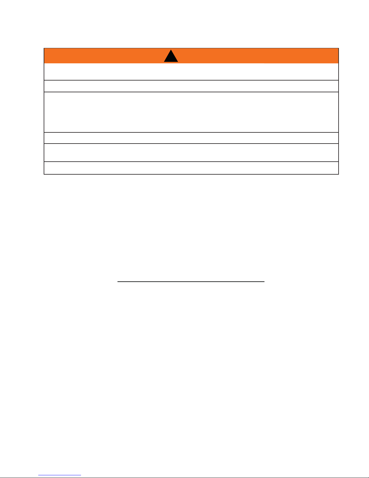
SYMPTOM PROBLEM TEST SOLUTION
Remote controls
Crystalite / Night light
but no spark or fl ame.
Main burner fl ame
is a blue, lazy,
transparent fl ame.
Flames are
consistently too
large or too small.
Carboning occurs.
B
Carbon is being
deposited on
glass, logs,
rocks, media
or combustion
chamber
surfaces.
White / grey fi lm
forms.
Remote is locked out. - Reset by turning power source off then on.
Blockage in vent. - Remove blockage. In really cold conditions, ice
Incorrect installation. - Refer to “VENTING” section to ensure correct
Unit is over-fi red or
underfi red.
A
Air shutter has become
blocked.
Flame is impinging on the
glass, logs, rocks, media
or combustion chamber.
Sulphur from fuel is being
deposited on glass, logs
or combustion chamber
surfaces.
37
NOTE: If back up batteries are installed, they
must also be removed to re-program.
buildup may occur on the terminal and should
be removed as required. To minimize this from
happening again, it is recommended that the vent
lengths that pass through unheated spaces (attics,
garages, crawl spaces) be wrapped with an insulated
mylar sleeve. Prevent sleeve from sagging. Contact
your local authorized dealer for more information.
location of storm collars.
- Check pressure readings:
Inlet pressure can be checked by turning screw (A)
counter-clockwise 2 or 3 turns and then placing pressure
gauge tubing over the test point. Gauge should read
7” (minimum 4.5”) water column for natural gas or 13”
(minimum 11”) water column for propane. Check that main
burner is operating on ‘HI’. Outlet pressure can be checked
the same as above using screw (B). Gauge should read
3.5” water column for natural gas or 10” water column for
propane. Check that main burner is operating on ‘HI’.
AFTER TAKING PRESSURE READINGS, BE SURE TO
TURN SCREWS CLOCKWISE FIRMLY TO RESEAL. DO
NOT OVER TORQUE.
Leak test with a soap and water solution.
- Ensure air shutter opening is free of lint or other
obstructions.
- Check that the glass, logs, rocks, media are correctly
positioned.
- Open air shutter to increase the primary air.
- Check the input rate: check the manifold pressure
and orifi ce size as specifi ed by the rating plate.
- Check that the door gasketing is not broken or
missing and that the seal is tight.
- Check that both vent liners are free of holes and well
sealed at all joints.
- Check that minimum rise per foot has been adhered
to for any horizontal venting.
- Clean the glass with a recommended gas fi replace
glass cleaner. DO NOT CLEAN GLASS WHEN HOT.
- If deposits are not cleaned off regularly, the glass
may become permanently marked.
42.1B
W415-1033 / A / 10.12.11
Page 38

38
SYMPTOM PROBLEM TEST SOLUTION
Exhaust fumes
smelled in room,
headaches.
Pilot will not light.
Makes noise with
no spark at pilot
burner.
Pilot will not light.
Makes no noise
with no spark
at pilot burner.
Crystalites™ and
(optional) blower
operates.
Appliance is spilling. - Ensure exhaust bracket gasket seal.
- Check door seal.
- Check for exhaust blockage.
- Check that venting is installed correctly.
- Room is in negative pressure; increase fresh air supply.
Wiring. - Verify the wire for the sensor and the wire for the ignitor
are connected to the correct terminals (not reverse) on
the module and pilot assembly.
Loose connection. - Verify no loose connections, electrical shorts in the
wiring or ground out to any metal object.
Igniter Spark gap is
incorrect.
A shorted or loose
connection.
Module is not grounded. - Verify the valve and pilot assemblies are properly
Ignition box has been
locked out.
NOTE: Starting from OFF, press the ON button on the transmitter. Approximately 4
seconds after the ON/OFF button is pressed the ignition board will start the spark.
The fi rst try for ignition will last approximately 60 seconds. If there is no fl ame ignition
(rectifi cation) the board will stop sparking for approximately 35 seconds. After the
wait time the board will start the second try for ignition by sparking for approximately
60 seconds. If there is still no positive ignition, the board will go into lock out.
- Spark gap of the ignitor to the pilot should be .125”
(1/8”).
- Remove and reinstall the wiring harness that plugs into
the module.
- Remove and verify continuity of each wire in the wiring
harness.
grounded to the metal chassis of the fi replace.
Choose one of the 4 methods below to reset the system.
1. To reset ignition box when locked out. Turn off power
supply and remove batteries (if used) from the receiver.
2. To reset the DFC Board when the board goes into a
lock out condition and the LED is blinking 3 times using
the transmitter ON/OFF button:
Step 1: Turn the system off by pressing the ON/
OFF button to turn the system off.
Step 2: After approximately 2 seconds press the
ON/OFF button on the transmitter again. THE DFC
Board will reset and the ignition sequence will start
again.
3. To reset the DFC Board when the board goes into a
lock out condition and the LED is blinking 3 times by
cycling fl ame:
Step 1: In the manual fl ame control mode, use
the down arrow button to reduce the fl ame to
off, indicated by the word OFF displayed on the
trasmitter LCD screen.
Step 2: Wait approximately 2 seconds and press
the up arrow button, the ignition sequence will
start.
4. To reset the DFC Board when the board goes into a
lock out condition and the LED is blinking 3 times using
the receiver switch.
Step 1: With the transmitter off, move the slider
switch on the receiver to the OFF position.
Step 2: Wait approximately 2 seconds and move
the receiver slider switch to the ON position. The
ignition sequence will start again.
W415-1033 / A / 10.12.11
42.1_2
Page 39

SYMPTOM PROBLEM TEST SOLUTION
Pilot sparks but
will not light.
Continues to
spark and pilot
lights, but main
burner will not
light.
Appliance won’t
perform any
functions.
Night light or
(optional) blower
won’t function
Gas supply. - Verify that the incoming gas line ball valve is “Open”.
- Verify that the inlet pressure reading is within
acceptable limits, inlet pressures must not exceed 14”
W.C.
Module is not grounded. - Verify the value and pilot assemblies are properly
grounded to the metal chassis of the fi replace.
Out of propane gas. - Fill the tank.
Short or loose connection
in sensor rod.
Poor fl ame rectifi cation or
contaminated sensor rod.
Poor grounding between
pilot assembly and gas
valve.
Damaged pilot or dirty
sensor rod.
Receiver switch is in the
wrong position.
No power to the system. - Check breaker to verify it’s in the “ON” position.
Transmitter isn’t
operational.
Control module switch is
in the wrong position.
COM switch is
unplugged.
Verify all connections. Verify the connections from the
pilot assembly are tight; also verify these connections
are not grounding out to any metal.
- Verify the fl ame is engulfi ng the sensor rod. This
will increase the fl ame rectifi cation. Verify correct
pilot orifi ce is installed and inlet gas specifi cations
to manual. (Remember, the fl ame carries the
rectifi cation current, not the gas. If the fl ame lifts from
pilot hood, the circuit is broken. A wrong orifi ce or too
high of an inlet pressure can cause the pilot fl ame to
lift.) The sensor rod may need cleaning.
- Verify that the wire harness is fi rmly connected to
module.
- Verify that the ceramic insulator around the sensor
rod is not cracked, damaged, or loose. Verify the
connection from the sensor rod to the sensor wire.
Clean sensor rod with an emery cloth to remove
any contamination that may have accumulated on
the sensor rod. Verify continuity with multimeter with
ohms set at the lowest range.
- Verify that the 3 position switch on the receiver is in
the “REMOTE” position (middle).
- Check battery power and battery orientation.
- Verify ON/OFF switch is in the “I” position which
denotes on.
- Verify “COM” switch is plugged into the front of the
control module.
39
42.1_3
W415-1033 / A / 10.12.11
Page 40

40
11.0 WARRANTY
NAPOLEON® products are manufactured under the strict Standard of the world recognized ISO 9001 : 2008 Quality Assurance
NAPOLEON® products are designed with superior components and materials assembled by trained craftsmen who take great
pride in their work. The burner and valve assembly are leak and test-fi red at a quality test station. The complete appliance is
again thoroughly inspected by a qualifi ed technician before packaging to ensure that you, the customer, receives the quality
NAPOLEON® GAS APPLIANCE PRESIDENT’S LIFETIME LIMITED WARRANTY
The following materials and workmanship in your new NAPOLEON® gas appliance are warranted against defects for as long as
you own the appliance. This covers: combustion chamber, heat exchanger, stainless steel burner, phazer™ logs and embers, rocks,
ceramic glass (thermal breakage only), gold plated parts against tarnishing, porcelainized enameled components and aluminum
extrusion trims.*
Electrical (110V and millivolt) components and wearable parts such as blowers, gas valves, thermal switch, switches, wiring, remote
controls, ignitor, gasketing, and pilot assembly are covered and NAPOLEON® will provide replacement parts free of charge during
the fi rst year of the limited warranty.*
Labour related to warranty repair is covered free of charge during the fi rst year. Repair work, however, requires the prior approval of
an authorized company offi cial. Labour costs to the account of NAPOLEON® are based on a predetermined rate schedule and any
repair work must be done through an authorized NAPOLEON® dealer.
* Construction of models vary. Warranty applies only to components included with your specifi c appliance.
NAPOLEON® warrants its products against manufacturing defects to the original purchaser only. Registering your warranty is not necessary. Simply
provide your proof of purchase along with the model and serial number to make a warranty claim. NAPOLEON® reserves the right to have its
representative inspect any product or part thereof prior to honouring any warranty claim. Provided that the purchase was made through an authorized
NAPOLEON® dealer your appliance is subject to the following conditions and limitations:
Warranty coverage begins on the date of original installation.
This factory warranty is non-transferable and may not be extended whatsoever by any of our representatives.
The gas appliance must be installed by a licensed, authorized service technician or contractor. Installation must be done in accordance with the installation
instructions included with the product and all local and national building and fi re codes.
This limited warranty does not cover damages caused by misuse, lack of maintenance, accident, alterations, abuse or neglect and parts installed from
other manufacturers will nullify this warranty.
This limited warranty further does not cover any scratches, dents, corrosion or discoloring caused by excessive heat, abrasive and chemical cleaners nor
chipping on porcelain enamel parts, mechanical breakage of PHAZER™ logs and embers.
This warranty extends to the repair or replacement of warranted parts which are defective in material or workmanship provided that the product has been
operated in accordance with the operation instructions and under normal conditions.
After the fi rst year, with respect to this President’s Lifetime Limited Warranty, NAPOLEON® may, at its discretion, fully discharge all obligations with
respect to this warranty by refunding to the original warranted purchaser the wholesale price of any warranted but defective part(s).
NAPOLEON® will not be responsible for installation, labour or any other expenses related to the reinstallation of a warranted part and such expenses are
not covered by this warranty.
Notwithstanding any provisions contained in the President’s Lifetime Limited Warranty, NAPOLEON’S responsibility under this warranty is defi ned as
above and it shall not in any event extend to any incidental, consequential or indirect damages.
This warranty defi nes the obligations and liability of NAPOLEON® with respect to the NAPOLEON® gas appliance and any other warranties expressed or
implied with respect to this product, its components or accessories are excluded.
NAPOLEON® neither assumes, nor authorizes any third party to assume, on its behalf, any other liabilities with respect to the sale of this product.
NAPOLEON® will not be responsible for: over-fi ring, downdrafts, spillage caused by environmental conditions such as rooftops, buildings, nearby trees,
hills, mountains, inadequate vents or ventilation, excessive venting confi gurations, insuffi cient makeup air, or negative air pressures which may or may not
be caused by mechanical systems such as exhaust fans, furnaces, clothes dryers, etc.
Any damages to the appliance, combustion chamber, heat exchanger, plated trim or other components due to water, weather damage, long periods of
dampness, condensation, damaging chemicals or cleaners will not be the responsibility of NAPOLEON®.
All parts replaced under the President’s Limited Lifetime Warranty Policy are subject to a single claim.
During the fi rst 10 years NAPOLEON® will replace or repair the defective parts covered by the lifetime warranty at our discretion free of charge. From 10
years to life, NAPOLEON® will provide replacement parts at 50% of the current retail price.
All parts replaced under the warranty will be covered for a period of 90 days from the date of their installation.
The manufacturer may require that defective parts or products be returned or that digital pictures be provided to support the claim. Returned products are
to be shipped prepaid to the manufacturer for investigation. If a product is found to be defective, the manufacturer will repair or replace such defect.
Before shipping your appliance or defective components, your dealer must obtain an authorization number. Any merchandise shipped without
authorization will be refused and returned to sender.
Shipping costs are not covered under this warranty.
Additional service fees may apply if you are seeking warranty service from a dealer.
Warranty labour allowance is only for the replacement of the warranted part. Travel, diagnostic tests, shipping and other related charges are not covered
by this warranty.
Certifi cate.
product that you expect from NAPOLEON®.
CONDITIONS AND LIMITATIONS
ALL SPECIFICATIONS AND DESIGNS ARE SUBJECT TO CHANGE WITHOUT PRIOR NOTICE DUE TO ON-GOING PRODUCT
IMPROVEMENTS. NAPOLEON® IS A REGISTERED TRADEMARK OF WOLF STEEL LTD.
W415-1033 / A / 10.12.11
2.1B
Page 41

12.0 SERVICE HISTORY
41
43.1
W415-1033 / A / 10.12.11
Page 42

42
12.0 NOTES
W415-1033 / A / 10.12.11
44.1
Page 43

43
44.1
W415-1033 / A / 10.12.11
Page 44

44
W415-1033 / A / 10.12.11
44.1
 Loading...